HALO Bassinest Swivel Sleeper Instruction Manual

Adult assembly required. Keep small parts away from children. Styles and colors/colours may vary.
Electronics panel not available on Essentia models.
IMPORTANT: Read all instructions before assembly and use of this product. Keep instructions for future reference.
Recommended for infants up to 20 lbs.
Tools required: #2 Phillips screwdriver (not included)
Batteries required: 3 AA (not included)
Not required on Essentia series.
WARNING!
FAILURE TO FOLLOW THESE WARNINGS AND THE INSTRUCTIONS COULD RESULT IN SERIOUS INJURY OR DEATH.
- Read and follow instructions before assembly and use. If you do not have instructions, DO NOT use this product. Call 1-888-999-HALO or visit www.Halosleep.com.
- Before each use, inspect the HALO Bassinest® swivel sleeper for damaged hardware, loose or missing components or sharp edges. DO NOT use the Bassinest swivel sleeper if any parts are missing or broken. Contact or write HALO Innovations, Inc. for replacement parts and instructional literature if needed. DO NOT substitute parts.
- Discontinue use of this product when the child is showing signs of being able to pull up, rollover, push up or sit up unassisted, or is able to move out of the security of the walled sleep area.
- Never leave child unattended.
- This product is not intended to be resold after use or returned to a retailer. Due to safety concerns, HALO Innovations, Inc. cannot be held responsible for any product that has been resold after use or returned to a retailer.
FALL HAZARD
To help prevent falls, do not use this product when the infant begins to push up on hands and knees or has reached 20 pounds, whichever comes first. Always check that the bassinet is securely locked on the base/stand by pulling upwards on the bassinet bed.
SUFFOCATION HAZARD–INFANTS HAVE SUFFOCATED:
- In gaps between extra padding and side of the bassinet/cradle/crib.
- On soft bedding.
- Use only the pad provided by manufacturer. NEVER add a pillow, comforter, or another mattress for padding.
- NEVER place additional objects in the Bassinest swivel sleeper.
- ALWAYS ensure the pad is positioned correctly. Do not create any pockets between the pad and mesh sides.
- To reduce the risk of SIDS, pediatricians recommend healthy infants be placed on their backs to sleep, unless otherwise advised by your physician.
- If a sheet is used with the pad, use only the one provided by the bassinet, crib or cradle manufacturer or one specifically designed to fit the dimension of the bassinet, crib or cradle mattress.
- Never use plastic shipping bags or other plastic film as a mattress cover not sold or intended for that purpose. They can cause suffocation.
- Discard all plastic packing materials immediately after opening.
- Product is designed and is approved for use with one baby only. Do not use with more than one child at a time.
STRANGULATION HAZARD
- Strings can cause strangulation! DO NOT place items with a string around a child’s neck, such as hood strings or pacifier cords. DO NOT suspend strings over a bassinet/crib/cradle or attach strings to toys.
- DO NOT place the Bassinest swivel sleeper near a window or patio door where cords from blinds or drapes can strangle an infant.
INJURY HAZARD
- Never place more than one infant to sleep in the Bassinest swivel sleeper.
- Never carry the Bassinest swivel sleeper with an infant in it.
- Young children should not be allowed to play unsupervised in the vicinity of the Bassinest swivel sleeper
- Always remove child from the Bassinest swivel sleeper before adjusting height.
- When using Bassinest swivel sleeper sleep area on the base, always ensure that the sleeping area is secure to its base before use.
- The Bassinest swivel sleeper should be placed on a horizontal floor.
- Not for use in an automobile.
- Be aware of the risk of open fires and other sources of strong heat, such as electric bar fires, gas fires, etc. in the near vicinity of the Bassinest swivel sleeper.
- Do not place anything in the Bassinest swivel sleeper to elevate the mattress. The American Academy of Pediatrics states that elevation can result in the infant sliding to the foot of the crib into a position that might compromise respiration and is therefore not recommended.
HALO BASSINEST® SWIVEL SLEEPER – ASSEMBLY INSTRUCTIONS – IMPORTANT!
Please keep these instructions for future reference. Please read these instructions before assembly and use of this product.
- Adult assembly required.
- Tools not included.
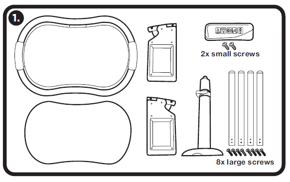
 Remove contents from carton and discard all packaging.
Electronics panel and screws not included on Essentia models.
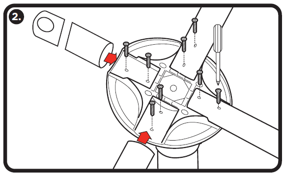
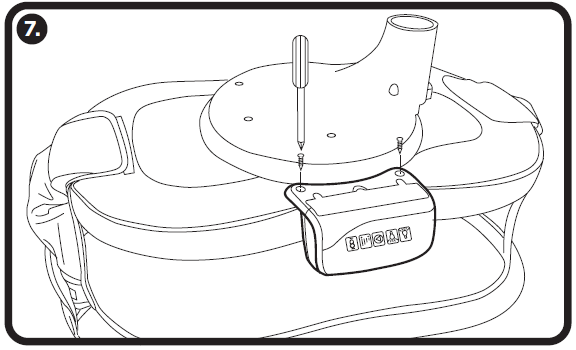
 Using a #2 Phillips screwdriver attach legs to underside of base using 8 new large screws provided. Tighten securely.
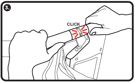
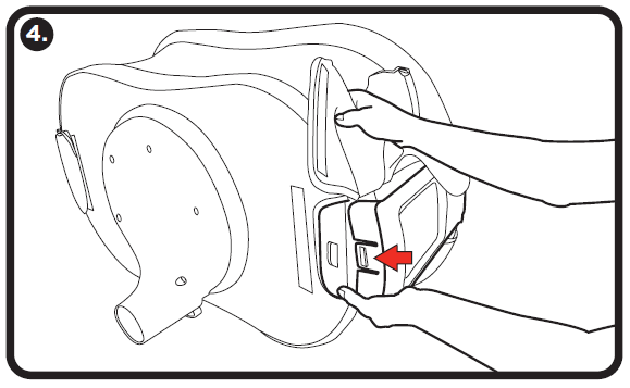
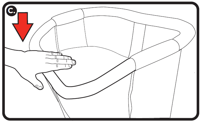
 Assemble the sleep area by fully opening the top flaps and side panels to expose the railing poles. Start by attaching railing marked “A” into sidewall opening marked “A”, and push together until spring pin engages. Repeat process with remaining railings and sidewall openings. Note that only one rail and sidewall connection will have a letter indicator.
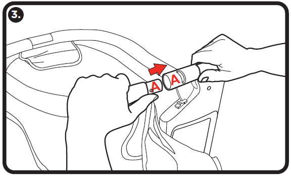
Railing “clicks” when properly assembled.
Pull on railing to ensure it is properly locked in place.
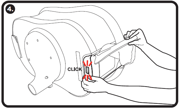
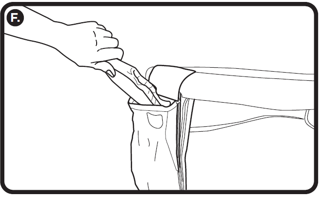
 It is necessary to detach fabric cover from fastener strip before inserting sidewall.
Slide bottom of sidewall into opening in base. Repeat on other side.
Sidewall “clicks” when properly installed. Pull on sidewall to ensure it is properly locked in place.
 On both ends of the Bassinest fold the fabric cover over the sidewall and secure using the fastener strip. Then fold the fabric flaps over top and bottom of sidewall and attach using the fastener tabs.
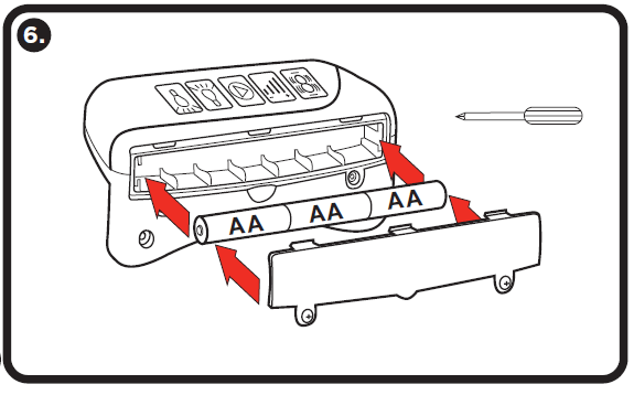
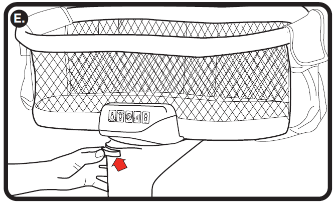
 Install batteries in Soothing Center.
(Not on Essentia models).
 Attach Soothing Center to the bottom of the sleep surface using the small screws provided. Tighten securely.
(Not on Essentia models).
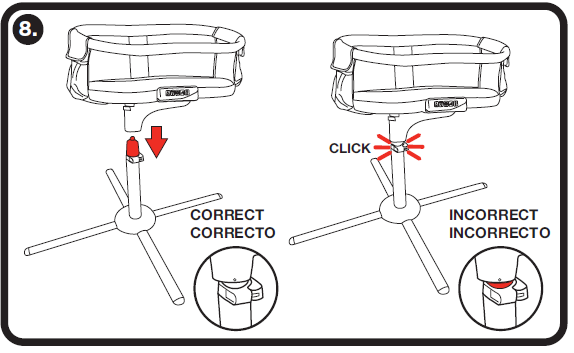
 Attach sleep area to base. Check to make sure no red stripe is visible on the post to confirm correct assembly.
 Add Mattress: Mattress comes with coordinated fitted sheet.
Please remove and wash sheet before use. Use only mattress and sheet especially designed for the Bassinest swivel sleeper.
DO NOT machine wash the mattress – instead wipe the surface clean with a damp cloth.
USE INSTRUCTIONS
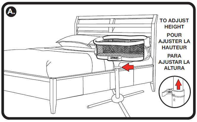
 To adjust height: Place by bed so that two legs are parallel to the side of the bed and one leg is under the bed. Release adjustment lever. Pull up on Bassinest bed to increase the height or push down on bed to lower. When bed is at desired height, close adjustment lever. Never adjust bed height with your baby in the bed.
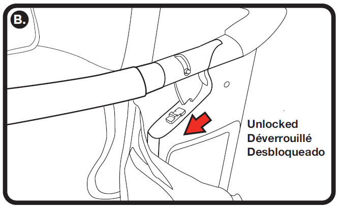
 To unlock retractable wall: On both ends of the Bassinest swivel sleeper, slide locking mechanisms out of sidewall notches as shown until front wall moves freely. It is not necessary to remove the fabric covering to access the locks. NOTE: If lock is difficult to use, lift up on retractable wall slightly and adjust lock as desired.
 To use retractable wall: Push down gently on front railing. Retractable wall automatically returns to its upright position when pressure is removed.
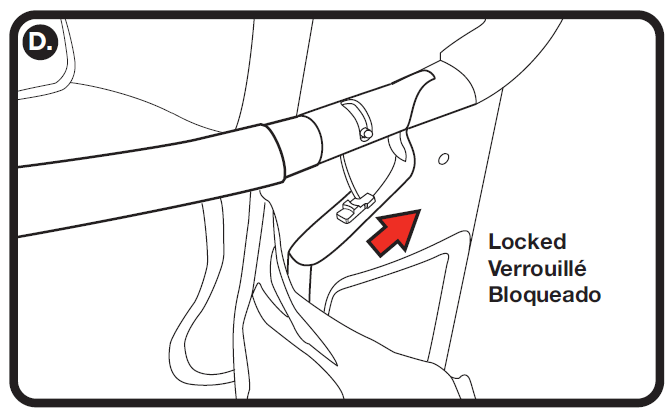
 To lock retractable wall: On both ends of the Bassinest swivel sleeper, slide locking mechanisms into sidewall notches as shown until front wall is immobilized.
 To remove bed from base: Push and hold release button while lifting to remove from post. Never remove sleep area from base with your baby in the bed. Never use sleep area when not attached to Bassinest base.
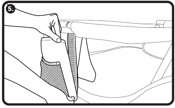
 To use storage pockets: Pull elastic band at top of pocket to open. Insert items for storage and easy access. Release to close. Do not store sharp objects or objects weighing more than 5 lbs.
 To move the Bassinest swivel sleeper: DO NOT attempt to move the Bassinest with your baby in the Bassinest. First remove the bed from the base or post. Move the base to the desired location and reattach the bed. Do not try to move the Bassinest swivel sleeper by lifting, pulling or pushing the bed while it is attached to the base or post.
SOOTHING CENTER OPERATION
(NOT AVAILABLE ON ESSENTIA MODELS)
NOTE: TO OPERATE, THREE (3) AA BATTERIES MUST BE INSTALLED.
SEE ASSEMBLY INSTRUCTIONS FOR MORE INFORMATION.
PREMIERE Model
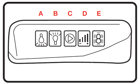
 (A) Floor Light: Activate the floor light by pushing the downward-facing bulb button. To turn off, push the button a second time. If not turned off manually, the floor light will automatically shut off after 15 minutes.
(B) Nightlight: Activate nightlight by pressing upward-facing bulb button. Press a second time to increase brightness. Press a third time to turn off. If not turned off manually, light will automatically shut off after 15 minutes.
(C) Soothing Sounds: Activate soothing sounds by pushing the play button. Press play button multiple times to cycle through sound options (heartbeat, white noise, babbling brook, rainforest). Press a final time to turn off soothing sounds. If not turned off manually, soothing sounds will automatically shut off after 30 minutes.
(D) Volume: Press for Low volume. Press a second time for High volume. Press a third time to turn off soothing sounds. If not turned off manually, soothing sounds will automatically shut off after 30 minutes
(E) Vibration: Activate vibration by pushing the vibration button. Press a second time for stronger vibration. Press a third time to shut off. If not turned off manually, vibration will automatically shut off after 30 minutes.
This device has been tested and found to comply with the limits for a Class B digital device, pursuant to Part 15 of the FCC rules.
HALO BASSINEST® SWIVEL SLEEPER – CARE AND MAINTENANCE INSTRUCTIONS
- Remove the sheet from the mattress and wash the sheet before use.
- The sheet is machine washable. Machine wash in warm water with like colors/colours. Do not use bleach. Tumble dry on low setting.
- The Bassinest swivel sleeper base, sleep area and mattress should be cleaned regularly by using a mild cleaning solution and a damp cloth. Do not use bleach. Do not machine wash mattress. Do not use harsh or abrasive cleaners. Rinse clean with water to remove residue. Allow to dry completely before replacing sleep pad and/or use.
- When not in use: clean unit as instructed. Store in a clean, dry location. Do not store outdoors or in a damp environment.
- Do not attempt to unscrew the sleep surface board or remove the lining cover from the board. This is not meant to be disassembled.
- If there is a large spill, spray a mixture of vinegar and water into the sides and wipe under the lining cover as much as you can until the spill or odor is gone. Let the top air dry before use.
- Do not submerge the Bassinest sleep surface board or walls in water.
BATTERY SAFETY INFORMATION (BATTERIES NOT INCLUDED)
In exceptional circumstances, batteries may leak fluids that can cause a chemical burn injury or ruin your product. To avoid battery leakage:
- Do not mix old and new batteries or batteries of different types: Alkaline, standard (carbon zinc), or rechargeable (nickel-cadmium).
- Insert batteries as indicated inside battery compartment.
- Remove batteries during long periods of non-use. Always remove exhausted batteries from the product. Dispose of batteries safely. Do not dispose of product in a fire. The batteries inside may explode or leak.
- Never short-circuit the battery terminals.
- Use only batteries of the same or equivalent type as recommended.
- Do not charge non-rechargeable batteries.
- Remove rechargeable batteries from the product before charging.
- If removable, rechargeable batteries are used, they are only to be charged under adult supervision.
WARRANTY
The HALO Bassinest® swivel sleeper is covered by a 1-year limited warranty.
Visit www.halosleep.com/halo-bassinest-1-year-limited-warranty/ for details.
CUSTOMER SERVICE
: Please contact your retailer.
: Please contact HALO.
Our friendly, specially trained support team will be happy to assist you with any concerns you may have regarding your new HALO Bassinest® swivel sleeper.

POWER CUBE
10000

OPERATING INSTRUCTIONS
PLEASE READ BEFORE OPERATING THIS EQUIPMENT
HALO POWER CUBE 10000
Thank you for choosing HALO. The POWER CUBE 10000 is the best of both worlds. It combines the on-the-go appeal of the original HALO portable charger, with a versatile design that can be recharged just about anywhere, and anytime. Simply charge your power cube in a wall outlet or car charging port and it’s ready to provide power on the go to your small electronics. Equipped with 10000 mAh and dual USB. Includes the Micro USB cable and USB Type C cable.
Please read the operating instructions carefully before using the HALO POWER CUBE 10000.
INCLUDED ITEMS
– HALO POWER CUBE 10000
– Micro USB Cable
– USB C Cable
- Wall Charging Plug
- Car Charging Plug
- LCD Digital Display
- USB Power ON/OFF Button
- 2x USB Output Ports
OPERATING INSTRUCTIONS
CHARGING YOUR HALO POWER CUBE 10000
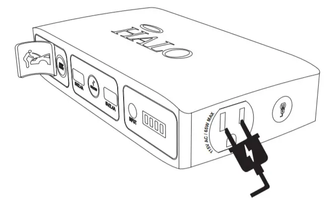
IMPORTANT: Before using your HALO POWER CUBE 10000 for the first time, fully charge it.
To charge your HALO POWER CUBE 10000, pull out the AC prongs & connect to a wall outlet. When you’re on the road, you can also use the car charging plug to charge your HALO POWER CUBE 10000.
While charging, the LCD Digital Display will illuminate indicating the charge percentage.
HALO POWER CUBE 10000 LCD DIGITAL DISPLAY
While charging, the digital screen will illustrate the charge percentage of the HALO POWER CUBE 10000. When fully charged, disconnect from charging.
CHARGING YOUR PERSONAL ELECTRONIC DEVICE
Charge up to two electronic devices using the supplied micro USB Cable or USB C Cable. Plug the USB connector into the HALO POWER CUBE 10000. Insert the tip into your personal electronic device and charging will begin automatically. You may also use your own USB cable that was supplied with your personal electronic device.
Note: To charge both the HALO POWER CUBE 10000 and your personal electronic device, first plug the HALO POWER CUBE 10000 into either a wall outlet or car outlet. Using any Standard USB Cable, connect your personal electronic device to the HALO POWER CUBE 10000 and your personal electronic device will automatically begin to charge. Once you’re personal electronic device is fully charged, the HALO POWER CUBE 10000 will then begin to charge itself.
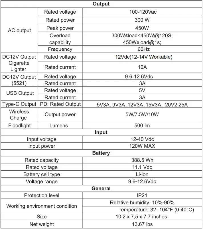
SPECIFICATIONS
| Battery Capacity: USB Output 1: USB Output 2: Rated AC Input: Rated DC Input: Dimensions (W x H x D): Weight: Working Temperature (charging): Working Temperature (discharging): Working Humidity: |
10000mAh 5V/2.1A 5V/2.1A 100V~240V, 50/60 Hz 2.75 x 2.75 x 1.57 Inches |
IMPORTANT SAFETY INSTRUCTIONS
SAVE THESE INSTRUCTIONS
WARNING: When using this product, basic precautions should always be followed, including the following:
- Read all the instructions before using the product.
- To reduce the risk of injury, close supervision is necessary when the product is used near children.
- Do not put fingers or hands into the product.
- Do not expose the power bank to rain or snow.
- Use of a power supply or charger not recommended or sold by power pack manufacturer may result in a risk of fire or injury to persons.
- Do not use the power bank in excess of its output rating. Overload outputs above rating may result in a risk of fire or injury to persons.
- Do not use the power bank that is damaged or modified. Damaged or modified batteries may exhibit unpredictable behavior resulting in re, explosion, or risk of injury.
- Do not disassemble the power bank. Take it to a qualified service person when service or repair is required. Incorrect reassembly may result in a risk of e or injury to persons.
- Do not expose a power pack to fire or excessive temperature. Exposure to re or temperature above 100°C may cause an explosion. The temperature of 100°C can be replaced by the temperature of 212°F.
- Have servicing performed by a qualified repair person using only identical replacement parts. This will ensure that the
safety of the product is maintained. - Switch o the power bank when not in use.
- Improper use of this product may result in product damage, excess heat, toxic fumes, or explosion, for which damages you (“Purchaser”), and not HALO2CLOUD LLC. (HALO) (“Manufacturer”) are responsible.
- This product should be operated only in open-air conditions. It should not be operated in an enclosed, unventilated space such as a carrying bag, pocket, purse, or bedding. Failure to follow these instructions may damage the product by overheating.
- Be cautious of drops, bumps, abrasions, or other impacts to this product. If there is any damage to the product such as dents, punctures, tears, deformities, or corrosion due to any cause, discontinue use. Contact Manufacturer or dispose of it in an appropriate manner at your local battery-recycling center.
- Do not disassemble this product or attempt to re-purpose or modify it in any manner.
- Do not attempt to replace any part of this device.
- For questions or instructions for the various ways to charge this device, refer to the illustrations in this operating instructions.
- If this device is accessible to or may be used by a minor, purchasing adult agrees to be solely responsible for providing supervision, instruction, and warnings. Purchaser agrees to defend, indemnify, and hold Manufacturer harmless for any claims or damages arising from unintended use or misuse by a minor.
- All products have gone through a thorough quality assurance inspection. If the sound that your device is excessively hot, is emitting odor, is deformed, abraded, cut, or is experiencing or demonstrating an abnormal phenomenon, immediately stop all product use and contact the Manufacturer.
- Never dispose of batteries in the garbage. Disposal of batteries in the garbage is unlawful under state and federal environmental laws and regulations. Always take used batteries to your local battery recycling center.
- Switch off the portable battery when not in use. The portable battery will automatically switch off when disconnected from a device.
- This device has been evaluated to meet general RF exposure requirements. The device can be used in portable exposure conditions without restriction.
COMPLIANCE WITH FCC REGULATION
This device complies with part 15 of the FCC Rules and RSS-Gen of IC Rules. Operation is subject to the following two conditions: (1) This device may not cause harmful interference, and (2) this device must accept any interference received, including interference that may cause undesired operation.
NOTE: This equipment has been tested and found to comply with the limits for a Class B digital device, pursuant to part 15 of the FCC Rules. These limits are designed to provide reasonable protection against harmful interference in a residential installation. This equipment generates, uses, and can radiate radio frequency energy and, if not installed and used in accordance with the instructions, may cause harmful interference to radio communications. However, there is no guarantee that interference will not occur in a particular installation.
If this equipment does cause harmful interference to radio or television reception, which can be determined by turning the equipment o and on, the user is encouraged to try to correct the interference by one or more of the following measures:
- Reorient or relocate the receiving antenna.
- Increase the separation between the equipment and receiver.
- Connect the equipment into an outlet on a circuit different from that to which the receiver is connected.
- Consult the dealer or an experienced technician for help.
CAUTION: To comply with the limits of the Class B digital device, pursuant to Part 15 of the FCC Rules, this device must be used with certified peripherals and shielded cables. All peripherals must be shielded and grounded. Operation with non-certified peripherals or non-shielded cables may result in interference to radio or reception.
MODIFICATION: Any changes or modifications of this device could void the warranty.
LEGAL
The manufacturer shall not in any way be liable to you or to any third party for any damages you or any third party may suffer as a result of use, intended or unintended, or misuse of this product in conjunction with any device or accessory other than the appropriate device for which this product is designed. The manufacturer will not be responsible for any damages you or any third party may super as a result of misuse of this product as outlined above. Purchaser agrees to defend, indemnify, and hold Manufacturer harmless for any claims or damages arising from unintended use or misuse, including use with an unintended device.
LIMITED WARRANTY
HALO2CLOUD LLC. (HALO) warrants its products to be free from defects in material and workmanship under normal use.
Conditions are as follows:
- During the first 90 days from the date of purchase, HALO will repair or replace the defective product.
- HALO will, subject to inspection, repair the defective product or replace it with a new or reconditioned unit. The return must be accompanied by a Return Merchandise Authorization (RMA) number to be issued upon request and must be shipped prepaid.
- Where applicable, all requests for warranty returns must be accompanied by proof of purchase.
- The warranty does not extend to the electronic equipment that is used or incorporates with any of our products and accessories. HALO shall not be held responsible for the improper use of its products.
- In no event shall HALO be liable for any incidental, special, consequential, or punitive damages arising out of the use of
HALO’s products.
For all questions or exchange requests, please call 888-907-6274, or contact us at zagg.com/support. This Limited Warranty sets forth the full scope of HALO’s obligations and liabilities with respect to the product. All implied warranties, including without limitation the implied warranties of merchantability and fitness for a particular purpose, are limited to the duration of this Limited Warranty. In no event shall HALO be liable for any incidental, special, consequential, or punitive damages or any damages or losses of or to electronic equipment or products that are used with any of HALO’s products.

FOR TECHNICAL SUPPORT
PLEASE REACH US AT:
ZAGG.COM/SUPPORT
OR
CALL US AT: 888-907-6274
HALO
6 CENTRAL ROW
HARTFORD, CT 06103
WWW.ZAGG.COM/HALO

Designed by HALO.
6 Central Row, Hartford, CT 06103
Made in China.
![]()

OPERATING INSTRUCTION
PLEASE READ BEFORE OPERATING THIS EQUIPMENT
HALO BOLT AIR
Thank you for choosing HALO!
Powerful and loaded with features including a new, easy-to-use digital display, the HALO BOLT AIR can be used to safely jump-start your vehicle or inflate your tires. The HALO BOLT AIR provides portable power so you can charge your phone, tablet, and other electronic devices anywhere! The HALO BOLT AIR also includes a convenient
floodlight and emergency light. Compact, versatile, and simple to use, the HALO BOLT AIR and all accessories fit neatly in its carrying pouch and is perfect to store in your home or vehicle for everyday use or an emergency need. Never be without a charge, a jump start, or a flat tire again!
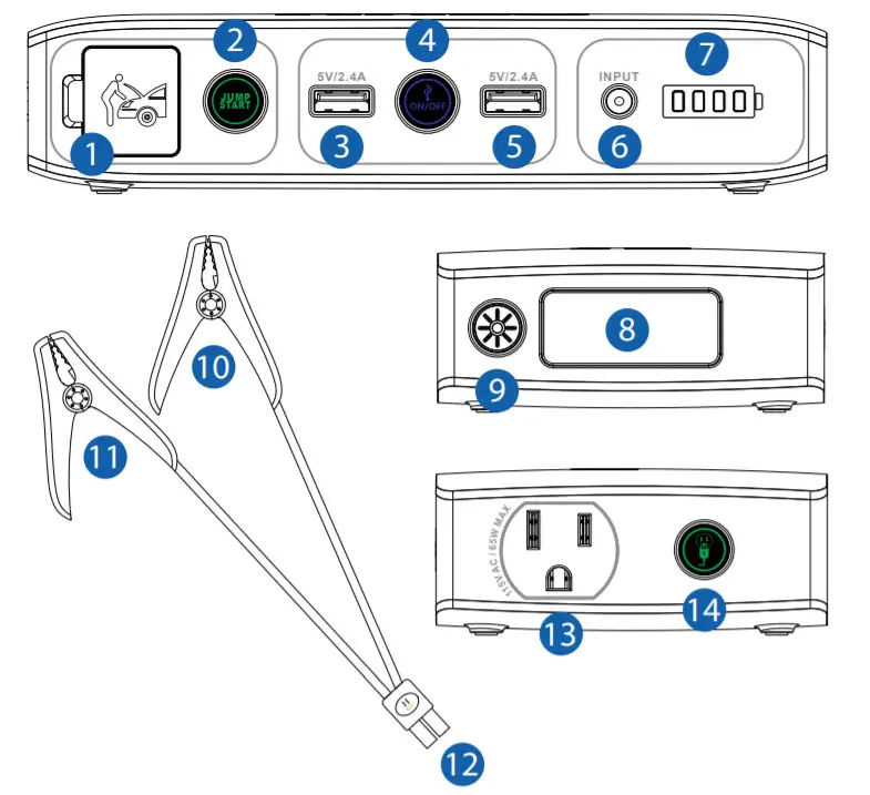
INCLUDED ITEMS
| – HALO BOLT AIR
– Jumper Cables – USB to Micro USB Cable – Carrying Pouch |
– Car Charging Adapter
– Wall Charging Adapter – 4 Interchangeable Air Nozzles – 12 Inch Air Hose Extension |
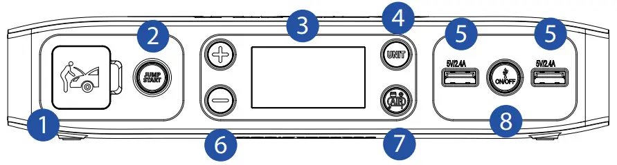
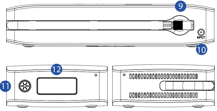
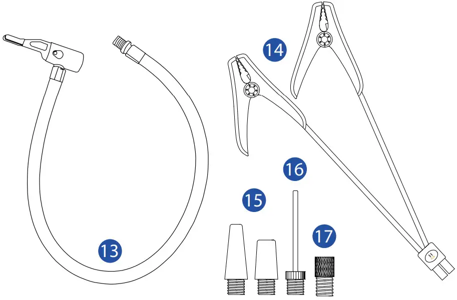
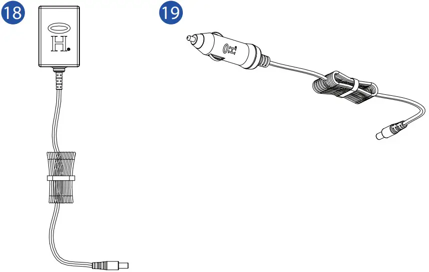
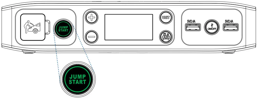
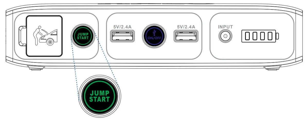
| 1 | Jump Start Output 2 | Jump Start Button 3 | Digital Screen 4 | Pressure Unit Button 5 | USB Outputs 6 | Pressure Settings (+) and (-) 7 | Air Compressor ON/OFF Button 8 | USB ON/OFF Button 9 | Air Hose |
10 | Charging Input 11 | Floodlight ON/OFF Button 12 | Floodlight/Emergency Light 13 | 12 Inch Air Hose Extension 14 | Jumper Cable Clamps 15 | Tapered Adapter (x2) 16 | Sports Ball Needle Adapter 17 | Presta Valve Adapter 18 | Wall Charging Adapter 19| Car Charging Adapter |
OPERATING INSTRUCTIONS
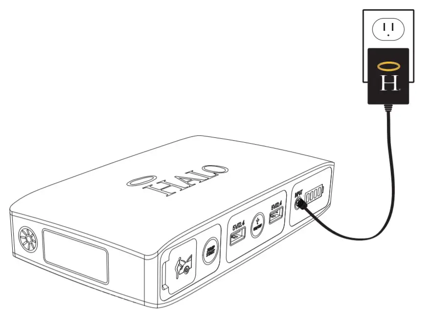
CHARGING YOUR HALO BOLT AIR
IMPORTANT: Before using your HALO BOLT AIR for the first time, fully charge it (so that pressing any button, displays 100% on the digital screen).
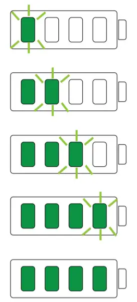
To charge your HALO BOLT AIR, use the provided Wall Charging Adapter, and plug the AC adapter plug into the charge input. Next, connect the AC adapter to a wall outlet. The HALO BOLT AIR will automatically begin charging. When the HALO BOLT AIR is fully charged, allfive battery indicator lights will be solid green and the
digital screen will indicate 100% charge. (This could take up to 9 hours). 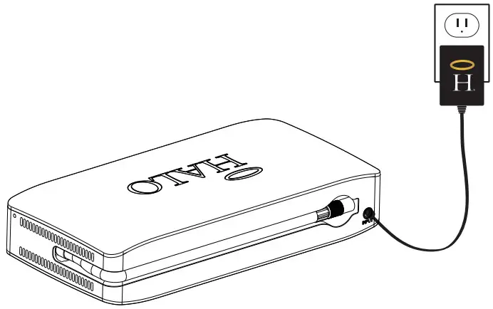 While charging, the digital screen will illustrate the charge percentage of the HALO BOLT AIR. When fully charged, disconnect the cable.
 NOTE:
NOTE:
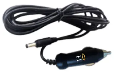
The HALO BOLT AIR is designed to charge between 32°F-113°F (0-45° C). A “TEMP” indicator will be illustrated on the digital display if the HALO BOLT AIR is attempted to be charged outside of this temperature range. When you’re on the road, you can also use the supplied Car Charging Adapter to charge your HALO BOLT AIR.
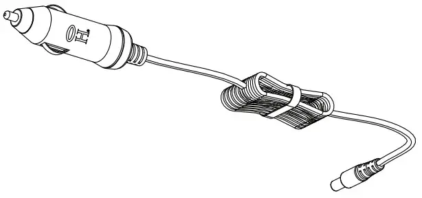
JUMP STARTING YOUR VEHICLE WITH THE HALO BOLT AIR
- Plug the jumper cables into the jump start output on the HALO BOLT AIR.
 NOTE:
NOTE:
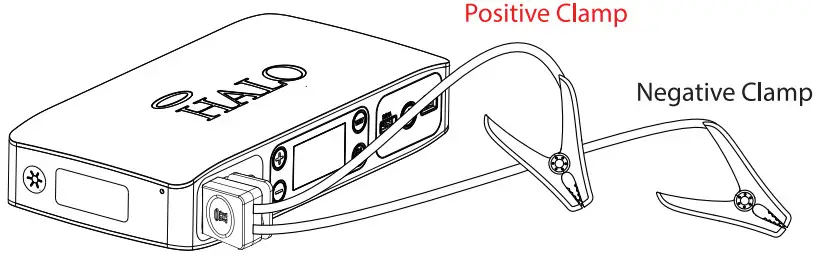
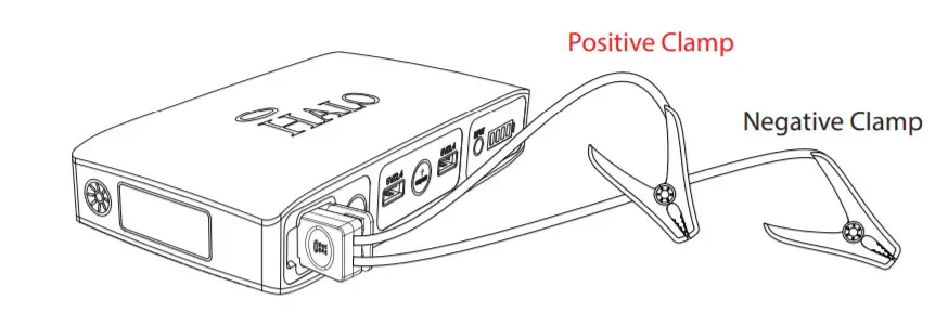
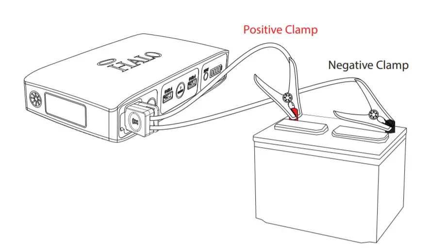
Make sure the jumper cables are fully plugged into the jump start output before trying to jump your vehicle. - Attach the jumper cable clamps to the vehicle battery.
– Red clamp on positive terminal (+)
– Black clamp on negative terminal (-)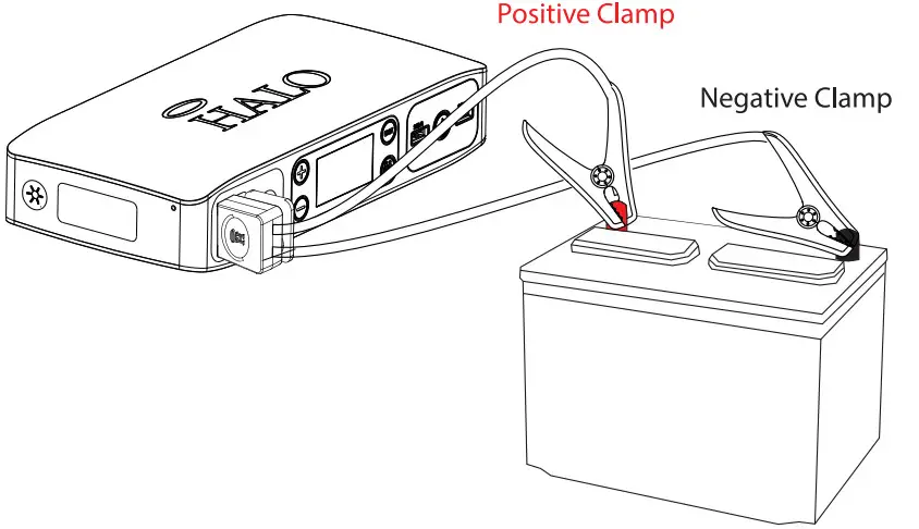 NOTE:
NOTE:
Do not touch red (positive) and black (negative) clamps together at any point. If the jump start button flashes red, the jumper cables have been connected incorrectly. If this flashing red condition occurs, disconnect the jumper cables from the HALO BOLT AIR and vehicle battery and restart the process from Step 1. - Press the “Jump Start” button and wait for the solid green light.
 NOTE:
NOTE:
A flashing green light indicates safety checks are in progress. - Start your vehicle.
NOTE:
The HALO BOLT AIR will allow 3 consecutive jump-start attempts after each time you press the jump start button. You must allow up to 15 seconds between each jump-start attempt. During the 15 seconds, the jump start button will flash green while the HALO BOLT AIR performs its safety checks. Once the jump start button illuminates solid green, the HALO BOLT AIR is ready for the next jump start attempt.
If your vehicle does not start after three attempts, we recommend you consult a certified mechanic.
Disconnect the jumper cable clamps from the car battery.
NOTE:
The jump start function can not be used in conjunction with USB charging or the air compressor. Please ensure that you have not activated the USB or Air Compressor output modes when attempting to jump-start your vehicle.
NOTE:
The HALO BOLT AIR is designed to allow a jump start when used within a safe temperature range. A “TEMP” indicator will be illustrated on the digital display if used outside of the temperature operating range.
JUMPSTART TROUBLESHOOTING TIPS
| Condition | Potential Cause | Solution |
 HALO BOLT AIR Jump HALO BOLT AIR JumpThe start button has been pressed but nothing happens |
The USB OWOFF Button or the Air The compressor ON/OFF Button has been pressed. |
The jump start output can not be used in conjunction with the USB output or air compressor modes. Ensure that both USB and AIR Compressor modes are off. |
| 1 HALO BOLT AIR displays a red “BOLT TOO LOW” message |
The HALO BOLT AIR is not sufficiently charged to jump-start the vehicle. |
Recharge the HALO BOLT AIR and verify at least 50% charged. Then try the jump-start the process again. |
| HALO BOLT AIR Jump Start button flashes red |
The jumper cables have not been properly connected to the vehicle battery. |
Check the jumper cables and ensure that the red clamp is connected to the positive terminal (+) and the the black clamp is connected to the negative terminal (-). |
 HALO BOLT AIR Jump HALO BOLT AIR JumpStart button flashes green continuously |
 The HALO BOLT AIR is The HALO BOLT AIR iswaiting to te connected to a battery or a SAFETY CHECK FAIL has been triggered. |
Check the jumper cables and ensure they are properly connected to the battery. If the SAFETY CHECK FAIL indicator is triggered during the jump start process, it is recommended that you consult with a certified mechanic. |
 HALO BOLT AIR HALO BOLT AIRdisplays yellow . “TEMP” message |
The HALO BOLT AIR has detected a low or high-temperature condition |
Disconnect the HALO BOLT AIR and allow the unit to acclimate to temperature operating range (0I-12011. |
| HALO BOLT AIR displays a green “VEHICLE BATTERY OK” message |
The HALO BOLT AIR detects that it is connected to a vehicle battery with a normal starting voltage |
It is recommended that you consult with a certified mechanic |
| HALO BOLT AIR Shuts off unexpectedly |
The HALO BOLT AIR detects that it is connected to ai reveal direct bast: aneryTht hast could indicate that the vehicle battery or another component is faulty. |
It recommended that you consult with a certified mechanic |
| HALO BOLT AIR Jump Start and On/Off button flashes red and blue |
This could occur when attempting to jumpstart a vehicle while other electrical components (i.e. headlights. heater. radio, etc.) are on |
Turn off your headlights and any other components that may drain your car battery and try the jump start the process again. |
| The vehicle battery may be faulty. | It is recommended that you consult with a certified mechanic |
NOTE:
If none of these troubleshooting tips work, please consult a certified mechanic for assistance.
HALO BOLT AIR COMPRESSOR
The HALO BOLT AIR comes equipped with a 12 Inch Air Hose Extension and 4 Interchangeable Air Nozzles. Simply twist on the corresponding nozzle to inflate balls, pool floaties, bike tires, and more!
1. Connect the air hose to the tire or use the appropriate nozzle to connect to your inflatable device
2. Press the (+) or (-) button to set the desired pressure. The pressure measuring units can be changed by pressing the UNIT button.
3. Once the desired pressure has been set, begin inflating by pressing the Air Compressor ON/OFF button. The air compressor will shut off automatically once the pressure has been reached.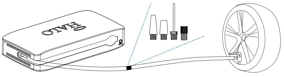
NOTE:The air compressor can be started or stopped at any point by pressing the air compressor ON/OFF button. The (+) and (-) may belong pressed to set the desired pressure quickly. Note: Always check and follow the manufacturer’s recommended pressure. Use caution as the air hose and connectors may get hot after extended use. The HALO BOLT AIR compressor is designed to automatically stop after an extended run-time or if an over-temperature protection setpoint is reached.
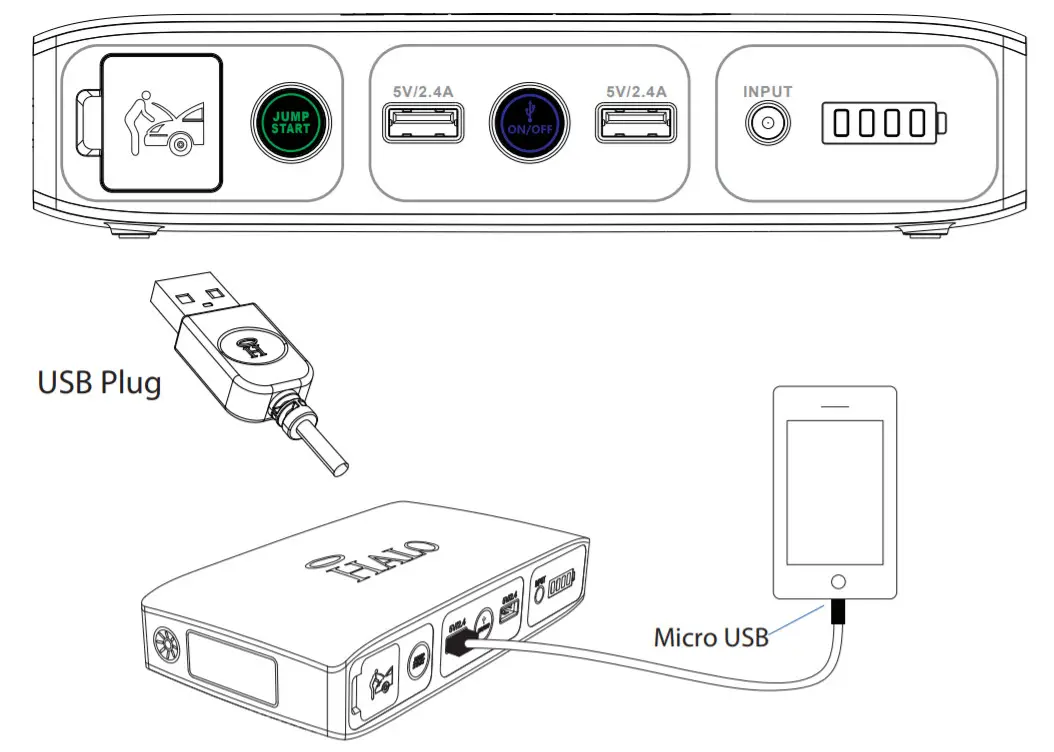
CHARGING AN ELECTRONIC DEVICE USING A 5V/2.4A USB OUTPUT PORT
1. Connect the Micro USB tip of the supplied Micro USB cable into the Micro USB input of your electronic device and connect the Standard USB end of the supplied Micro USB cable into either one of the HALO BOLT AIR USB 5V/2.4A Output ports.
NOTE:
If your electronic device does not have a Micro USB Input, your HALO BOLT AIR is also compatible with the charging cable provided with your electronic device. To use, plug the standard USB end of the cable into either one of the two 5V/2.4A USB Output ports located on your HALO BOLT AIR.
2. Turn on the USB charging by pressing the USB Power ON/OFF Button on the HALO BOLT AIR.
NOTE:
The HALO BOLT AIR USB charging feature will automatically power off after 30 minutes of inactivity.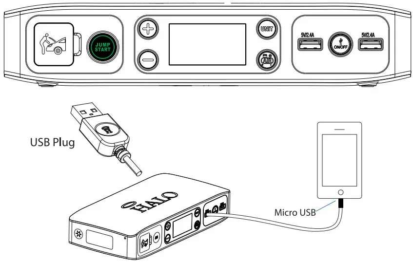 HALO SMART CHARGE TECHNOLOGY
Your HALO BOLT AIR contains the HALO SMART CHARGE TECHNOLOGY to achieve higher compatibility for charging standard 5V USB electronic devices. The HALO SMART CHARGE TECHNOLOGY will allow the HALO BOLT AIR to communicate with your electronic device and provide the fastest and safest charge for that device.
COMPATIBILITY
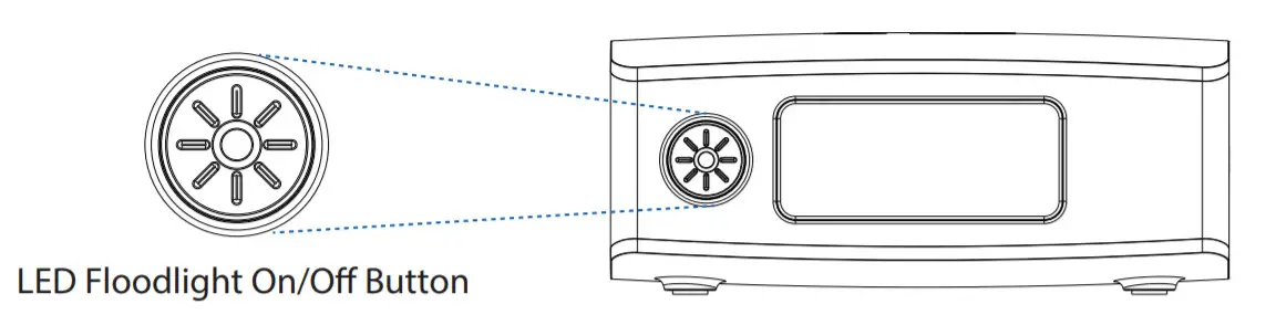
Standard 5V USB electronic devices including Mobile phones, Tablets, PSP, NDS, MP3, MP4, MP5, Bluetooth, GPS, Cameras, and more. USING YOUR HALO BOLT AIR FLOODLIGHT
The floodlight can be turned on and off by simply pressing and releasing the floodlight ON/OFF button. The first press will turn on the floodlight. A second press will turn on the red emergency light. The third press will turn on SOS flashing red light. The floodlight will automatically turn off after 2 hours of inactivity.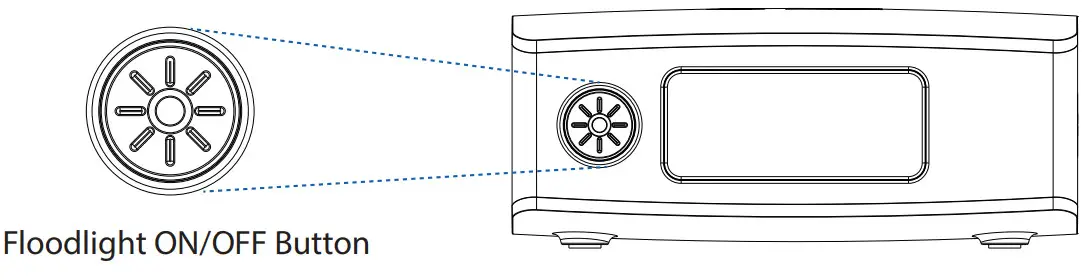 NOTE:
NOTE:
Do not look directly into the LED oodlight.
SPECIFICATIONS
| Battery Cells: Battery Pack Energy: Jump Start: Air Compressor: Input: USB Output: Dimensions: Weight: |
3x Li-Polymer 5300mAh 58830 mWh 12V/500Amps 100PSI max 14V/0.85A 2x USB 5V/2.4A 118 x 242 x 47mm 1150.10 g |
SAFETY PRECAUTIONS
- Read all instructions before using the product.
- Your HALO BOLT AIR should not be used to jump-start unregistered vehicles.
- Make sure the jumper cables are fully plugged into the jump start output before trying to jumpstart your vehicle.
- Caution: The lithium-ion rechargeable battery used in this charging device may present a risk of fire or chemical burn if mistreated. Do not disassemble, expose to heat above 212°F (100°C), or incinerate.
- Misusing or incorrectly connecting your HALO BOLT AIR may cause an electric shock to users and damage equipment.
- Your HALO BOLT AIR may become warm under extended high power operation. During operation, keep your HALO BOLT AIR away from materials that may be affected by these temperatures. Do not cover, wrap, or otherwise restrict the HALO BOLT AIR during operation.
- When used correctly, lithium-ion rechargeable batteries provide a safe and dependable source of portable power. However, if they are misused or abused, this may result in leakage, burns for the explosion, causing personal injury, or damage to other devices.
- Do not disassemble your HALO BOLT AIR. There are no user-serviceable parts inside. Incorrect reassembly may result in shock or flre-hazard.
- Do not drop or be subject to strong impacts. Do not operate your HALO
BOLT AIR if it has received a sharp blow, or has otherwise been damaged in any way. - Do not expose your HALO BOLT AIR to moisture, water, rain, or snow.
- Do not insert any object into the ports or openings of your HALO BOLT AIR.
- Only charge your HALO BOLT AIR by the specified method with the specified charging adapter provided with the unit.
- In the unlikely event of leakage or explosion use sand or a chemical fire extinguisher.
- Ensure there is no metal object between your device and the HALO BOLT AIR when charging your device wirelessly as the object may become hot.
- Batteries should be recycled or disposed of as per state and local guidelines.
- Keep your HALO BOLT AIR dry and away from moisture and corrosive materials. The HALO BOLT AIR should not be used near water or wet areas such as bathtubs, showers, bathrooms, sinks, swimming pools, or basements.
- Do not clean your HALO BOLT AIR with harsh chemicals, soaps, or detergents. Just wipe the case with a soft cloth.
- Keep your HALO BOLT AIR away from heat sources, including open faames, radiators, stoves, ovens, and any other devices that produce heat.
- Do not puncture, crush or be subject to mechanical shock.
- Make sure the HALO BOLT AIR’s charging ports do not become contaminated with lint or other debris. Use a canned-air type of product periodically to ensure that the port openings are clear.
- Recharge your HALO BOLT AIR once every three months when not in use.
COMPLIANCE WITH FCC REGULATION
This device complies with part 15 of the FCC Rules and RSS-Gen of IC Rules. Operation is subject to the following two conditions: (1) This device may not cause harmful interference, and (2) this device must accept any interference received, including interference that may cause undesired operation.
NOTE: This equipment has been tested and found to comply with the limits for a Class B digital device, pursuant to part 15 of the FCC Rules. These limits are designed to provide reasonable protection against harmful interference in a residential installation. This equipment generates, uses, and can radiate radio frequency energy and, if not
installed and used in accordance with the instructions, may cause harmful interference to radio communications. However, there is no guarantee that interference will not occur in a particular installation. If this equipment does cause harmful interference to radio or television reception, which can be determined by turning the equipment off and on, the user is encouraged to try to correct the interference by one or more of the following measures: - Reorient or relocate the receiving antenna.
- increase the separation between the equipment and receiver.
- Connect the equipment into an outlet on a circuit different from that to which the receiver is connected.
- Consult the dealer or an experienced technician for help.
CAUTION: To comply with the limits of the Class B digital device, pursuant to Part 15 of the FCC Rules, this device must be used with certified peripherals and shielded cables. All peripherals must be shielded and grounded. Operation with non-certified peripherals or non-shielded cables may result in interference to radio or reception.
LIMITED WARRANTY
HALO2CLOUD LLC. (HALO) warrants its products to be free from defects in material and workmanship under normal use. Conditions are as follows:
- During the first 90 days from the date of purchase, HALO will repair or replace the defective product.
- HALO will, subject to inspection, repair the defective product or 13 | POWER YOUR LIFE replace it with a new or reconditioned unit. The return must be accompanied by a Return Merchandise Authorization (RMA) number to be issued upon request and must be shipped prepaid.
- Where applicable, all requests for warranty returns must be accompanied by proof of purchase.
- The warranty does not extend to the electronic equipment that is used or incorporates with any of our products and accessories. HALO shall not be held responsible for the improper use of its products.
- In no event shall HALO be liable for any incidental, special, consequential, or punitive damages arising out of the use of HALO’s products. For all questions or exchange requests, please call 888-907-6274, or email us at [email protected]. This Limited Warranty sets forth the full scope of HALO’s obligations and liabilities with respect to the product. All implied warranties, including without limitation the implied warranties of merchantability and fitness for a particular purpose, are limited to the duration of this Limited Warranty. In no event shall HALO be liable for any incidental, special, consequential, or punitive damages or any damages or losses of or to electronic equipment or products that are used with any of HALO’s products.
FOR TECHNICAL SUPPORT PLEASE EMAIL US AT:
[email protected]
OR
CALL US AT: 888-907-6274
HALO
6 CENTRAL ROW
HARTFORD, CT 06103
WWW.BESTHALO.COM
Designed by HALO.
6 Central Row, Hartford, CT 06103
Made in China.

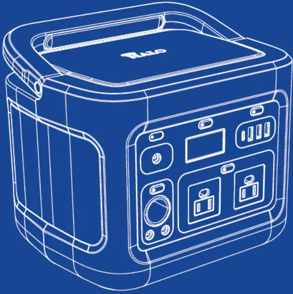
HALO Portable Power Station Instructions
INCLUDED ITEMS
– HALO PORTABLE POWER STATION
– AC Wall Charging Adapter
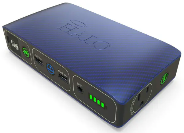
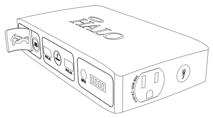
LOCATION OF CONTROLS
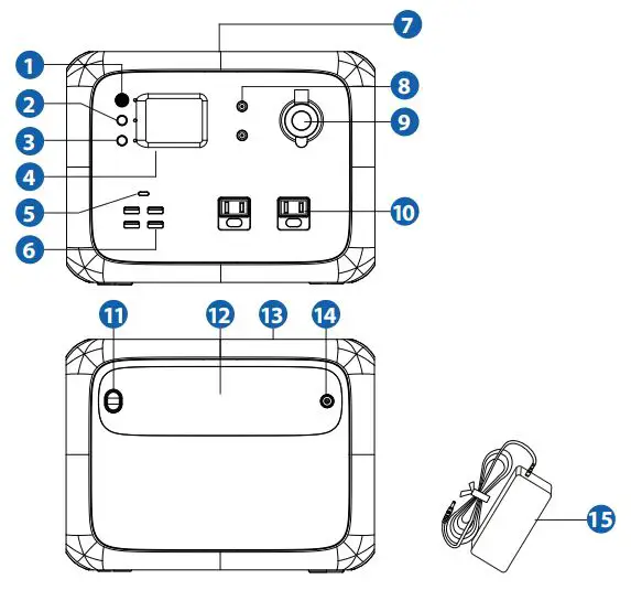
- Power ON/OFF Button
- DC ON/OFF Button
- AC ON/OFF Button
- LCD Screen
- Type-C PD Output Port
- USB Output Ports
- Wireless Charging Pad
- 12V DC 5521 Output Ports
- 2V DC Power Socket
- 120V AC Output Ports
- Floodlight ON/OFF Button
- Floodlight
- Collapsible Handles
- DC Input
- AC Wall Charging Adapter
OPERATING INSTRUCTIONS
Please make sure to fully charge the HALO PORTABLE POWER STATION before first use.
CHARGING THE HALO PORTABLE POWER STATION
Using the AC Wall Charging Adapter:
Use the provided AC Wall Charging Adapter, and plug the AC adapter tip into the DC charge input. Next, connect the AC Wall Charging Adapter into a wall outlet. The HALO PORTABLE POWER STATION will automatically begin charging. When the HALO PORTABLE POWER STATION is fully charged, all five battery indicator lights will be solid blue and the LCD digital display will indicate 100%. When fully charged, disconnect the cable.
NOTE:
- While charging the LCD display will enter into standby mode. The LCD display can be reactivated by pressing any button.
- The HALO PORTABLE POWER STATION can also be charged via solar panel (not included) and car charger (not included).
- The HALO PORTABLE POWER STATION can be charged and discharged simultaneously.
BUTTON OPERATIONS
Power ON/OFF Button:
To turn ON, press and hold the Power ON/OFF Button for 2 seconds. The LCD Screen will light up. To turn OFF the HALO PORTABLE POWER STATION, press and hold for 2 seconds.
DC ON/OFF Button:
To turn ON, press and hold DC ON/OFF Button for 2 seconds. The DC Indicator will light up and the LCD Screen will display “DC ON”. To turn OFF, press and hold for 2 seconds. The LCD Screen will display “DC OFF”.
AC ON/OFF Button:
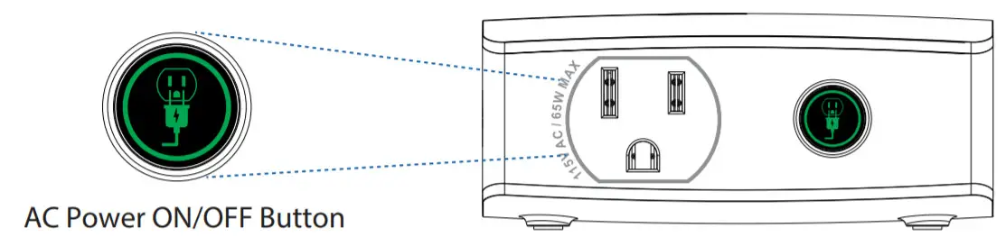
To turn ON, press and hold the AC ON/OFF Button for 2 seconds. The AC Indicator will light up and the LCD Screen will display “AC ON” . To turn OFF, press and hold the AC ON/OFF Button for 2 seconds. The LCD Screen will display “AC OFF”.
NOTE:
To save battery, turn off the unit when not in use.
CONNECTING YOUR ELECTRONIC DEVICES, EQUIPMENT AND APPLIANCES
The HALO PORTABLE POWER STATION is compatible with AC and DC electronic devices, equipment and appliances where portable, stationary, or emergency power is required.

There are several ways to power and charge electronic devices with the HALO PORTABLE POWER STATION. Both AC and DC Output Ports can be used simultaneously.
Using the 120V AC Output Ports:
The HALO PORTABLE POWER STATION can be used to power your 120V AC electronic devices, equipment and appliances rated for 300Watts or less. To begin, connect the AC power plug from your device/equipment/appliance into the AC Output Port of the HALO PORTABLE POWER STATION. Press and hold the AC ON/OFF Button for 2 seconds.
NOTE:
- Make sure the AC Power Plug is fully plugged into the AC Output Port.
- The HALO PORTABLE POWER STATION will provide up to 450Watts peak power for a short duration.
Using the USB Ports:
The HALO PORTABLE POWER STATION is compatible with the USB charging cable provided with your electronic device. To begin, press and hold the DC ON/OFF Button for 2 seconds. Plug the standard USB end of the cable into any of the 5V/3A USB Output Ports. Connect the tip into the input of your electronic device to begin charging. For PD (Power Delivery) Output, use a Type-C USB to Type-C cable (not included) to charge your compatible electronic devices.
HALO USB Smart Charge Technology
Your HALO PORTABLE POWER STATION contains the HALO USB SMART CHARGE TECHNOLOGY to achieve higher compatibility for charging USB electronic devices. The HALO USB SMART CHARGE TECHNOLOGY will allow the HALO PORTABLE POWER STATION to communicate with your electronic device and provide the fastest and safest charge for that device.
Using the Wireless Charging Pad:
To begin, press and hold the DC ON/OFF Button for 2 seconds. Place your wireless compatible device on top of the HALO PORTABLE POWER STATION to begin charging.
NOTE:
- Check your smart phone to confirm it is charging. If it is not charging, adjust the position of the phone on top of the HALO PORTABLE POWER STATION.
- Ensure there is no metal obstruction on the back of the phone or phone case, or credit cards inside the phone case while wirelessly charging.
Using the 12V DC Power Socket and 5521 Output Ports
The HALO PORTABLE POWER STATION can be used to power your 12V DC electronic devices, equipment and appliances. To begin, press and hold the DC ON/OFF Button for 2 seconds. Connect your 12V compatible device/equipment/appliance into the Power Socket or 5521 Output Port(s).
USING YOUR HALO PORTABLE POWER STATION FLOODLIGHT
To begin, turn on the main power by pressing and holding the POWER ON/OFF Button for 2 seconds.
Press the Floodlight ON/OFF Button once to turn ON.
Press the Floodlight ON/OFF Button twice to turn 50% brightness.
Press the Floodlight ON/OFF Button three times to turn SOS function.
Press the Floodlight ON/OFF Button four times to turn OFF.
TROUBLESHOOTING
If the HALO PORTABLE POWER STATION can not charge or power devices, please check the following steps:
- Make sure the Power ON/OFF Button is ON.
- Make sure the AC and DC Power Buttons are ON and confirm the LED on the right of the buttons are green.
- Check the battery capacity. If it is lower than 10%, please recharge the HALO PORTABLE POWER STATION.
- Make sure the load power connected does not exceed the rated power of the port.
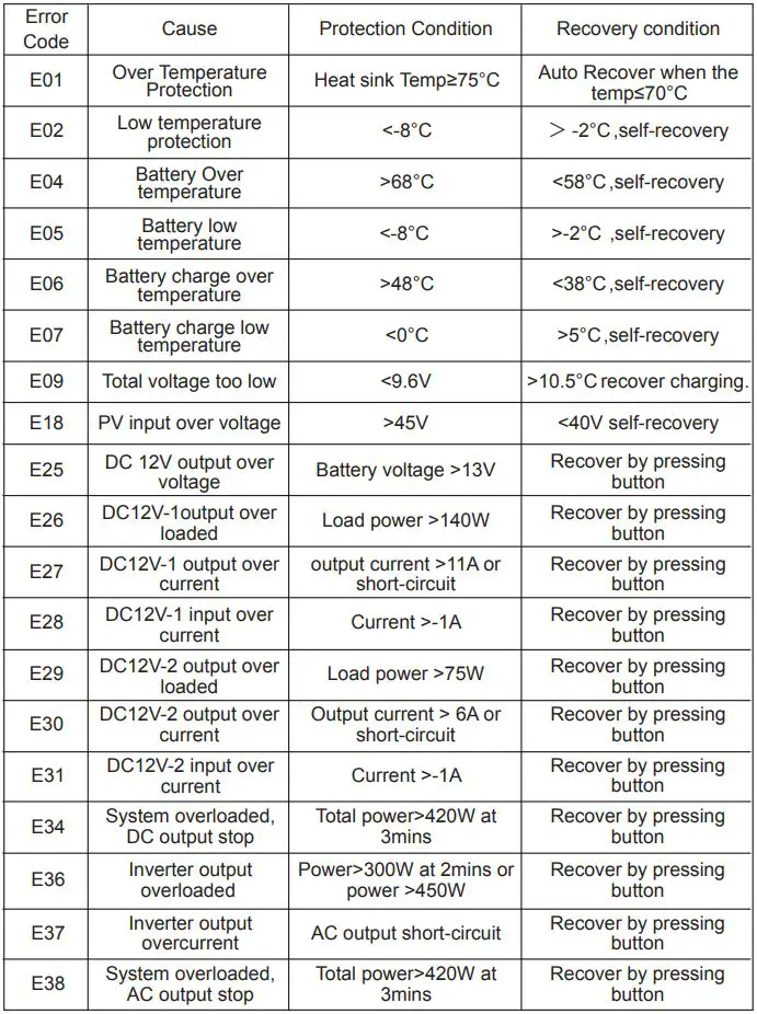
- If an error code is observed, refer to the Error Code Chart on the next page.
SPECIFICATIONS
SAFETY PRECAUTIONS
- Read all instructions before using the product.
- Do not get your HALO PORTABLE POWER STATION wet or store in extreme temperature conditions.
- Do not disassemble or attempt to repair your HALO PORTABLE POWER STATION yourself.
- Use a cloth to clean the exterior of your HALO PORTABLE POWER STATION. Do not use liquid detergent or chemicals of any kind.
- When used correctly, lithium- ion rechargeable batteries provide a safe and dependable source of portable power. However, if they are misused or abused, this may result in leakage, burns, fire or explosion, causing personal injury or damage to other devices.
- Misusing or incorrectly connecting your HALO PORTABLE POWER STATION may cause electric shock to users and damage equipment.
- Keep your HALO PORTABLE POWER STATION dry and away from moisture and corrosive materials. The HALO PORTABLE POWER STATION should not be used near water or wet areas such as bathtubs, showers, bathrooms, sinks, swimming pools or basements.
- Do not expose your HALO PORTABLE POWER STATION to moisture, water, rain, or snow.
- Keep your HALO PORTABLE POWER STATION away from heat sources, including open flames, radiators, stoves, ovens, and any other devices that product heat.
- The lithium-ion rechargeable battery used in this charging device may present a risk of fire or chemical burn if mistreated. Do not expose to fire or excessive temperature. Do not expose to heat above 212°F (100°C) or incinerate.
- In the unlikely event of leakage or explosion use sand or a chemical fire extinguisher.
- Your HALO PORTABLE POWER STATION may become warm under extended high power operation. Do not cover, wrap, or otherwise restrict the HALO PORTABLE POWER STATION during operation.
- Do not disassemble your HALO PORTABLE POWER STATION. There are no user-serviceable parts inside. Incorrect reassembly may result in shock or fire hazard.
- Do not drop or subject to strong impacts. Do not operate your HALO PORTABLE POWER STATION if it has received a sharp blow, or has otherwise been damaged in any way.
- Do not puncture, crush or subject to mechanical shock.
- Only charge your HALO PORTABLE POWER STATION by the specified method with the specified charging adapter provided with the unit.
- Do not use any non-HALO-branded accessories with the HALO PORTABLE POWER STATION. Doing so may cause electric shock to users and damage equipment.
- The HALO PORTABLE POWER STATION, along with its accessories, are not toys and should be kept away from children.
- Do not insert any foreign object into the ports or openings of your HALO PORTABLE POWER STATION.
- Do not clean your HALO PORTABLE POWER STATION with harsh chemicals, soaps or detergents. Just wipe the case with a soft cloth.
- Do not modify or attempt to repair the HALO PORTABLE POWER STATION except as indicated in the instructions for use and care.
- Make sure the HALO PORTABLE POWER STATION’s charging ports do not become contaminated with lint or other debris. Use a canned-air type of product periodically to ensure that the port openings are clear.
- Batteries should be recycled or disposed of as per state and local guidelines.
- The device shall be stored indoors and protected from the elements;
- The unit shall not be charged outdoors.
- When in use, steps should be taken to reduce the exposure to rain, sleet, snow, and the like.
- For appliance and battery storage, do not exceed 104°F (40°C)
- Under abusive conditions, liquid may be ejected from the battery; avoid contact. If contact accidentally occurs, flush with water. If liquid contacts eyes, additionally seek medical help. Liquid ejected from the battery may cause irritation or burns.
SAVE THESE INSTRUCTIONS
FCC RADIATION EXPOSURE STATEMENT
This equipment complies with FCC radiation exposure limits set forth for an uncontrolled environment. This equipment should be installed and operated with minimum distance 20 cm between the radiator and your body. Any changes or modification not expressly approved by the party responsible for compliance could void the user’s authority to operate the equipment.
COMPLIANCE WITH FCC REGULATION
This device complies with part 15 of the FCC Rules. Operation is subject to the following two conditions: (1) This device may not cause harmful interference, and (2) this device must accept any interference received, including interference that may cause undesired operation. NOTE: This equipment has been tested and found to comply with the limits for a Class B digital device, pursuant to part 15 of the FCC Rules. These limits are designed to provide reasonable protection against harmful interference in a residential installation. This equipment generates, uses, and can radiate radio frequency energy and, if not installed and used in accordance with the instructions, may cause harmful interference to radio communications. However, there is no guarantee that interference will not occur in a particular installation.
If this equipment does cause harmful interference to radio or television reception, which can be determined by turning the equipment off and on, the user is encouraged to try to correct the interference by one or more of the following measures:
- Reorient or relocate the receiving antenna.
- Increase the separation between the equipment and receiver.
- Connect the equipment into an outlet on a circuit different from that to which the receiver is connected.
- Consult the dealer or an experienced radio/TV technician for help. CAUTION: To comply with the limits of the Class B digital device, pursuant to Part 15 of the FCC Rules, this device must be used with certified peripherals and shielded cables. All peripherals must be shielded and grounded. Operation with non-certified peripherals or non-shielded cables may result in interference to radio or reception.
LIMITED WARRANTY
HALO warrants its products to be free from defects in material and workmanship under normal use. Conditions are as follows:
- During the first 90 days from date of purchase, HALO will repair or replace the defective product.
- HALO will, subject to inspection, repair the defective product or replace it with a new or reconditioned unit. The return must be accompanied by a Return Merchandise Authorization (RMA) number to be issued upon request, and must be shipped prepaid.
- Where applicable, all requests for warranty returns must be accompanied by a proof of purchase.
- The warranty does not extend to the electronic equipment that is used, or incorporates with any of our products and accessories. HALO shall not be held responsible for the improper use of its products.
- In no event shall HALO be liable for any incidental, special, consequential or punitive damages arising out of the use of HALO’s products.
For all questions or exchange requests, please call 888-907-6274, contact us at zagg.com/support or visit www.zagg.com/warranty-policies. This Limited Warranty sets forth the full scope of HALO’s obligations and liabilities with respect to the product. All implied warranties, including without limitation the implied warranties of merchantability and fitness for a particular purpose, are limited to the duration of this Limited Warranty. In no event shall HALO be liable for any incidental, special, consequential or punitive damages or any damages or losses of or to electronic equipment or products that are used with any of HALO’s products.
![]()
FOR TECHNICAL SUPPORT PLEASE CONTACT US AT:
ZAGG.COM/SUPPORT
OR
CALL US AT: 888 907 6274
HALO
6 CENTRAL ROW
HARTFORD, CT 06103
WWW.ZAGG.COM/HALO
© 2020 ZAGG Inc | www.ZAGG.com/HALO The HALO and H trademarks are the property of ZAGG Inc. All rights reserved.
ZAGG Inc | 910 W Legacy Center Way, Ste. 500, Midvale, Utah 84047 Made in China. ![]()
![]()
 PLEASE READ BEFORE OPERATING THIS EQUIPMENT.
HALO BOLT ACDC 58830
Thank you for choosing HALO!
Powerful, compact, and easy to use, the HALO BOLT ACDC 58830 can safely jump-start your car or charge your laptop. In addition, you can use it to charge your phone, tablet, or other electronic devices! The HALO BOLT ACDC 58830 also features a convenient LED floodlight.
INCLUDED ITEMS
– HALO BOLT ACDC 58830
– Jumper Cables
– USB to Micro USB Cable
– Carrying Pouch
– Car Charger
– AC Wall Charging Adapter
– Operating Instructions
– Quick Start Guide
LOCATION OF CONTROLS
| 1 | Jump Start Output 2 | Jump Start Button 3 | USB Output 1 4 | USB Power ON/OFF Button 5 | USB Output 2 6 | DC Input: DC 14V/.85A 7 | LED Battery Indicator |
8 | LED Floodlight 9 | LED Floodlight Button 10 | Positive Clamp 11 | Negative Clamp 12 | Jump Start Plug 13 | AC Output Port 14 | AC Power ON/OFF Button |
OPERATING INSTRUCTIONS
Please make sure to fully charge the HALO BOLT ACDC 58830.
CHARGING THE HALO BOLT ACDC 58830
To recharge the HALO BOLT ACDC 58830, use the provided AC wall charging adapter cable, and plug the AC adapter tip into the charge input.
Next, connect the AC adapter to a wall outlet. The HALO BOLT ACDC 58830 will automatically begin charging. When the HALO BOLT ACDC 58830 is fully charged, all four indicator lights will be solid green (This could take up to 9 hours).
When you’re on the road, you can also use the supplied car charger to charge your HALO BOLT ACDC 58830.
When your HALO BOLT ACDC 58830 is on, the LED indicator lights will display the power level.
HALO BOLT ACDC 58830 POWER LEVEL INDICATORS
| INDICATOR LIGHTS | HOW TO READ | AMOUNT OF CHARGE |
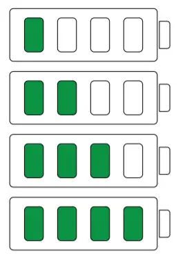 |
One solid light Two solid lights Three solid lights Four solid lights |
0%-25% 26%-50% 51%-75% 76%-100% |
HALO BOLT ACDC 58830 POWER LEVEL INDICATORS WHILE CHARGING:
| INDICATOR LIGHTS | HOW TO READ | AMOUNT OF CHARGE |
 |
First light blinking First light solid, second light blinking The first two lights are solid, third light blinking The first three lights are solid, fourth blinking All four lights solid |
0%-25% 26%-50% 51%-75% 76%-100% 100% fully charged |
JUMP STARTING YOUR VEHICLE WITH THE HALO BOLT ACDC 58830
- Plug the jumper cables into the jump start output on the HALO BOLT ACDC 58830.
 NOTE:
NOTE:
Make sure the jumper cables are fully plugged into the jump star output before trying to jump your vehicle. - Attach the jumper cable clamps to the vehicle battery.
– Red clamp on positive terminal (+)
– Black clamp on negative terminal (-)
 NOTE:
NOTE:
Do not touch red (positive) and black (negative) clamps together at any point. If the jump start button flashes red, the jumper cables have been connected incorrectly. If this fashing red condition occurs, disconnect the jumper cables from the HALO BOLT ACDC 58830 and vehicle battery and restart the process from Step 1. - Press the “Jump Start” button and wait for the solid green light.
 NOTE:
NOTE:
A fashing green light indicates safety checks are in progress. - Start your vehicle.
NOTE:
The HALO BOLT ACDC 58830 will allow 3 consecutive jump-start attempts after each time you press the jump start button. You must allow up to 15 seconds between each jump-start attempt. During the 15 seconds, the jump start button will flash green while the HALO BOLT ACDC 58830 performs its safety checks. Once the jump start button illuminates solid green, the HALO BOLT ACDC 58830 is ready for the next jump start attempt.
If your vehicle does not start after three attempts, we recommend you consult a certified mechanic. - Disconnect the jumper cable clamps from the car battery.
NOTE:
While jump-starting your vehicle, you cannot charge your electronic devices using the USB or AC output ports and you cannot charge the HALO BOLT ACDC 58830 via the AC wall charging adapter.
JUMPSTART TROUBLESHOOTING TIPS
| Condition | Potential Cause | Solution |
| HALO BOLT ACDC 58830 shuts off unexpectedly | The HALO BOLT ACDC 58830 is not sufficiently charged to jump-start the vehicle. | Recharge the HALO BOLT ACDC 58830. |
| The HALO BOLT ACDC 58830 detects that it is connected to a vehicle battery that does not require a jump start. This could indicate that the vehicle battery or other component is faulty. | It is recommended that you consult with a certified mechanic. | |
| HALO BOLT ACDC 58830 Jump Start and On/Off button flashes red and blue | This could occur when attempting to jump-start a vehicle while other electrical components (i.e. headlights, heater, radio, etc.) are on. | Turn of your headlights and any other components that may drain your car battery and try the jump-start the process again. |
| The vehicle battery may be faulty. | It is recommended that you consult with a certified mechanic. | |
| HALO BOLT AC DC 58830 battery indicators flash green |
The HALO BOLT ACM 38830 has detected an ugh temperature condition. | Disconnect the HALO BOLT ACDC 58830 and allow it to cool for several minutes. Then try the jumpstart process again. |
| HALO BOLT ACDC 58830 Jump Start button flashes red | The jumper cables have not been properly connected to the vehicle battery. | Check the jumper cables and ensure that the red clamp is connected to the positive terminal (+) and the black clamp is connected to the negative terminal (-) |
| HALO BOLT ACDC 58830 Jump Start button flashes green continuously | The HALO BOLT ACDC 58830 is waiting to be connected to a battery. | Check the jumper cables and ensure they are properly connected to the battery. |
| HALO BOLT ACDC 58830 Jump Start button has been pressed but nothing happens | The blue LED power button is ON. | Ensure the unit is OFF and then press the Jump Start button. |
NOTE:
If none of these troubleshooting tips work, please consult a certified mechanic for assistance.
CHARGING A LAPTOP (VIA THE AC OUTPUT PORT)
- Connect the AC power plug from your laptop (or another electronic device that is rated at 65 watts or less) into the AC output port of the HALO BOLT ACDC 58830.
NOTE:
Any electronic device can be powered by the AC output port as long as it is rated at 65 watts or less. BE SURE TO CHECK THAT YOUR LAPTOP OR OTHER ELECTRONIC DEVICE IS RATED AT 65 WATTS OR LESS.
- Press the AC Power ON/OFF Button and wait for a solid green light
NOTE:
Make sure the AC power plug is fully plugged into the AC output port before turning on the AC Power ON/OFF Button.
 NOTE:
NOTE:
A fashing green light indicates safety checks are in progress. If you see a flashing red light, the device you connected is rated for greater than 65 watts and cannot be powered using the HALO BOLT ACDC 58830. The HALO BOLT ACDC 58830 will automatically power off after 30 minutes of inactivity. While jump-starting your vehicle, you cannot charge your electronic devices using the USB or AC output ports and you cannot charge the HALO BOLT ACDC 58830 via the AC wall charging adapter.
LAPTOP CHARGING TROUBLESHOOTING TIPS
| Condition | Potential Cause | Solution |
| HALO BOLT ACDC 58830 AC button flashes red | Electronic device is rated at greater than 65 watts |
Only electronic devices rated at 65 watts or less can be used with the HALO BOLT ACDC 58830 |
| The HALO BOLT ACDC 58830 is not sufficiently charged to power the connected electronic device |
Recharge the HALO BOLT ACDC 58830 |
|
| HALO BOLT ACDC 58830 shuts off unexpectedly |
The HALO BOLT ACDC 58830 is not sufficiently charged to power the connected electronic device. |
Recharge the HALO BOLT ACDC 58830 |
| HALO BOLT ACDC 58830 battery indicators flash green |
The HALO BOLT ACDC 58830 has detected a high-temperature condition. |
Disconnect the HALO BOLT ACDC 58830 and allow it to cool for several minutes. Then try to power your device again. |
| A single LED battery indicator flashes green |
The HALO BOLT ACDC 58830 is getting low on power. | Recharge the HALO BOLT ACDC 58830 |
CHARGING AN ELECTRONIC DEVICE USING A 5V/2.4A USB OUTPUT PORT
- Connect the Micro USB tip of the supplied Micro USB cable into the Micro USB input of your electronic device and connect the Standard The USB end of the supplied Micro USB cable into either one of the HALO BOLT ACDC 58830 USB 5V/2.4A Output ports.
NOTE:
If your electronic device does not have a Micro USB Input, your HALO BOLT ACDC 58830 is also compatible with the charging cable provided with your electronic device. To use, plug the standard USB end of the cable into either one of the two 5V/2.4A USB Output ports located on your HALO BOLT ACDC 58830. - Turn on the USB charging feature by pressing and releasing the USB Power ON/OFF Button on the HALO BOLT ACDC 58830.
NOTE:
The HALO BOLT ACDC 58830 USB charging feature will automatically power off after 30 minutes of inactivity.
While jump-starting your vehicle, you cannot charge your electronic devices using the USB or AC output ports and you cannot charge the HALO BOLT ACDC 58830 via the AC wall charging adapter.
HALO SMART CHARGE TECHNOLOGY
Your HALO BOLT ACDC 58830 contains the HALO SMART CHARGE TECHNOLOGY to achieve higher compatibility for charging standard 5V USB electronic devices. The HALO SMART CHARGE TECHNOLOGY will allow the HALO BOLT ACDC 58830 to communicate with your electronic device and provide the fastest and safest charge for that device.
COMPATIBILITY
Standard 5V USB electronic devices including Mobile phones, Tablets, PSP, NDS, MP3, MP4, MP5, Bluetooth, GPS, Cameras, and more.

USING YOUR HALO BOLT ACDC 58830 FLOODLIGHT
The floodlight can be turned on and of by simply pressing and releasing the floodlight ON/OFF button. The floodlight will automatically turn of after 2 hours of inactivity.
NOTE:
Do not look directly into the LED floodlight.
MAINTENANCE AND CARE
– Do not get your HALO BOLT ACDC 58830 wet or stored in extreme temperature conditions.
– Do not disassemble or attempt to repair your HALO BOLT ACDC 58830 yourself.
– Use a soft cloth with soap to clean the exterior of your HALO BOLT ACDC 58830. Do not use liquid detergent or chemicals of any kind on your HALO BOLT ACDC 58830.
SAFETY PRECAUTIONS
– Your HALO BOLT ACDC 58830 has been designed and manufactured to ensure personal safety. Please read the following carefully before using. Incorrect operation or incompatibility with your personal electronic device may result in reduced battery performance or damage.
– Carefully read the operating instructions, and use your HALO BOLT ACDC 58830 correctly.
– Your HALO BOLT ACDC 58830 should not be used to jump-start unregistered vehicles.
– Make sure the jumper cables are fully plugged into the jump start output before trying to jump your vehicle.
– Caution: The lithium-ion rechargeable battery used in this charging device may present a risk of fire or chemical burn if mistreated. Do not disassemble, expose to heat above 212°F (100°C), or incinerate.
– Misusing or incorrectly connecting your HALO BOLT ACDC 58830 may cause an electric shock to users and damage equipment.
– Your HALO BOLT ACDC 58830 may become warm under extended high power operation. During operation, keep your HALO BOLT ACDC
58830 away from materials that may be affected by these temperatures.
– When used correctly, lithium-ion rechargeable batteries provide a safe and dependable source of portable power. However, if there are misused or abused, this may result in leakage, burns, fire or explosion, causing personal injury or damage to other devices.
– Do not disassemble your HALO BOLT ACDC 58830. There are no user-serviceable parts inside. Incorrect reassembly may result in shock or fire-hazard.
– Do not drop or be subject to strong impacts. Do not operate your HALO BOLT ACDC 58830 if it has received a sharp blow, or has otherwise been
damaged in any way.
– Do not expose your HALO BOLT ACDC 58830 to moisture, water, rain, or snow.
– Do not insert any object into the ports or openings of your HALO BOLT ACDC 58830.
– Only charge your HALO BOLT ACDC 58830 by the specified method with the specified cable.
– In the unlikely event of leakage or explosion use sand or a chemical fire extinguisher.
– Batteries should be recycled or disposed of as per state and local guidelines.
SPECIFICATIONS
Battery Cell: 3x Li-Polymer 5300mAh
Battery Pack Power: 58830 mWh
Input: DC 14V/0.85A
USB Output: 2x USB 5V/2.4A
AC Output: 1x AC output port 115V (65 Watts)
Dimensions: 182 x 97 x 40mm
Weight: 754 g
FCC COMPLIANCE STATEMENT
This device complies with Part 15 of the FCC Rules. Operation is subject to the following two conditions:
– This device may not cause harmful interference, and
– This device must accept any interference received, including interference that may cause undesired operation.
15.21
You are cautioned that changes or modifications not expressly approved by the party responsible for compliance could void the user’s authority to operate the equipment.
15.105(b)
This equipment has been tested and found to comply with the limits for a Class B digital device, pursuant to Part 15 of the FCC rules. These limits are designed to provide reasonable protection against harmful interference in a residential installation. This equipment generates, uses, and can radiate radio frequency energy and, if not installed and used in accordance with the instructions, may cause harmful interference to radio communications.
However, there is no guarantee that interference will not occur in a particular installation. If this equipment does cause harmful interference to radio or television reception, which can be determined by turning the equipment off and on, the user is encouraged to try to correct the interference by one or more of the following measures:
– Reorient or relocate the receiving antenna.
– Increase the separation between the equipment and receiver.
– Connect the equipment into an outlet on a circuit different from that to which the receiver is connected.
– Consult the dealer or an experienced radio/TV technician for help.
LIMITED WARRANTY
What does this limited warranty cover and how long is the coverage?
HALO INTERNATIONAL SEZC LTD warrants its products to be free from defects in material and workmanship under normal use and service for
a period of ninety (90) days beginning on the date your purchase the product.
What is not covered by this limited warranty?
This Limited Warranty does not cover defects or damage due to: (1) accidents, acts of God, misuse, abuse, abnormal use, abnormal conditions, improper storage, or exposure to liquid or moisture, (2) unusual or abnormal physical force or impact, including dropping off the product, (3) connection of the product to improper voltage supply or (4) attempted to repair or modification by anyone other than HALO or a facility authorized by HALO.
What are HALO’s obligations under this limited warranty?
Provided that you comply with the conditions of this Limited Warranty, during the duration of this Limited Warranty HALO will repair or replace the product, at its sole option, without charge. When repairing or replacing a product, HALO may, at its sole option, repair or replace the product with new, used, rebuilt, or reconditioned parts or products. HALO will warrant any product that is repaired or replaced under this Limited Warranty for a period equal to the remaining time period under the original Limited Warranty or ninety (90) days, whichever is longer.
What are the limits of HALO’s Liability?
This Limited Warranty sets forth the full scope of HALO’s obligations and liabilities with respect to the product. All implied warranties, including, without limitation, implied warranties of merchantability and fitness for a particular purpose, are limited to the duration of this Limited Warranty. In no event shall HALO be liable for any incidental, special, consequential, or punitive damages or any damages or losses of or to electronic equipment or products that are used with any of HALO’s products.
How does state law relate to this limited warranty?
Some states do not allow limitations on how long an implied warranty lasts or the disclaimer or limitation of incidental or consequential damages. Therefore, some or all of the disclaimers and limitations above may not apply to you.
![]()
FOR TECHNICAL SUPPORT PLEASE
EMAIL US AT:
SUPPORTFBESTHALO.COM
OR
CALL US AT: 888-907-6274
HALO INTERNATIONAL SEZC LTD
68 WEST BAY ROAD
GEORGETOWN, GRAND CAYMAN, KY1-1003
WWW.BESTHALO.COM

Designed by Halo International SEZC LTD. in the Cayman Islands
Patent Pending. Made in China.
POWER STATION

OPERATING INSTRUCTIONS
PLEASE READ BEFORE OPERATING THIS EQUIPMENT
 SAFETY PRECAUTIONS
DANGER-CAUTION Read and understand all safety information before using this product. Failure to follow these instructions may result In electrical shock, explosion, fire which may result in serious injuries, death, or property damage.
- Read all instructions before using the product.
- Do not get your HALO POWER STATION wet or store in extreme temperature conditions.
- Do not disassemble or attempt to repair your HALO POWER STATION yourself.
- Use a cloth to clean the exterior of your HALO POWER STATION. Do not use liquid detergent or chemicals of any kind.
- When used correctly, lithium-ion rechargeable batteries provide a safe and dependable source of portable power. However, if they are misused or abused, this may result in leakage, burns, fire, or explosion, causing personal injury or damage to other devices.
- Misusing or incorrectly connecting your HALO POWER STATION may cause an electric shock to users and damage equipment.
- Keep your HALO POWER STATION dry and away from moisture and corrosive materials. The HALO POWER STATION should not be used near water or wet areas such as bathtubs, showers, bathrooms, sinks, swimming pools, or basements.
- Do not expose your HALO POWER STATION to moisture, water, rain, or snow.
- Keep your HALO POWER STATION away from heat sources, including open flames, radiators, stoves, ovens, and any other devices that produce heat.
- The lithium-ion rechargeable battery used in this charging device may present a risk of fire or chemical burn if mistreated. Do not expose to fire or excessive temperature. Do not expose to heat above 212°F (100°C) or incinerate.
- Your HALO POWER STATION may become warm under extended high power operation. Do not cover, wrap, or otherwise restrict the HALO POWER STATION during operation.
- In the unlikely event of leakage or explosion use sand or a chemical fire extinguisher.
- Do not disassemble your HALO POWER STATION. There are no user-serviceable parts inside. Incorrect reassembly may result in shock or fire hazards.
- Do not drop or be subject to strong impacts. Do not operate your HALO POWER STATION if it has received a sharp blow, or has otherwise been damaged in any way.
- Do not puncture, crush or be subject to mechanical shock.
- Only charge your HALO POWER STATION by the specified method with the specified charging adapter provided with the unit.
- Do not use any non-HALO-branded accessories with the HALO POWER Doing so may cause an electric shock to users and damage equipment.
- The HALO POWER STATION, along with its accessories, are not toys and should be kept away from children.
- Do not insert any foreign object Into the pores or openings of your HALO POWER STATION.
- Do not clean your HALO POWER STATION with harsh chemicals, soaps, or detergents. Just wipe the case with a soft cloth.
- Do not modify or attempt to repair the HALO POWER STATION except as indicated in the instructions for use and care.
- Make sure the HALO POWER STATION’s charging ports do not become contaminated with lint or other debris.
- Batteries should be recycled or disposed of as per state and local guidelines.
- The device shall be stored indoors and protected from the elements;
- When in use, steps should be taken to prevent exposure to rain, sleet, snow, and the like.
- For appliance and battery storage, do not exceed 104°F (40°C)
- Do not operate in explosive atmospheres such as in the presence of flammable liquids, gases or dust.
SAVE THESE INSTRUCTIONS
INCLUDED ITEMS
– HALO POWER STATION
– Wall Charging Adapter

LOCATION OF CONTROLS
| 1. Input Power LED 2. DC Input 3. DC ON/OFF Button 4. 12V DC Power Socket 5. 12V DC 5525 Output Ports 6. Collapsible Handle 7. LCD Screen ON/OFF Button 8. LCD Screen |
9. USB Output ON/OFF Button 10. USB-A Output Ports 11. USB-C PD Input/Output Port 12. AC Output ON/OFF Button 13.110V AC Output Ports 14. Floodlight ON/OFF Button 15. Floodlight 16. Wall Charging Adapter |
OPERATING INSTRUCTIONS
Please make sure to fully charge the HALO POWER STATION before first use.
CHARGING THE HALO POWER STATION
Using the Wall Charging Adapter:
Use the provided Wall Charging Adapter, and plug the adapter tip into the DC charge input. Next, connect the Wall Charging Adapter into a wall outlet. The HALO POWER STATION will automatically begin charging. When the HALO POWER STATION is fully charged, all four battery indicator lights will be solid green and the LCD digital display will indicate 100%. When fully charged, disconnect the cable.
NOTE:
- For optional or dual charging, The HALO POWER STATION can also be charged via the USB-C PD port with a USB-C charging adapter (not included).
- The HALO POWER STATION can also be charged via solar panel (not included) and car charger (not included).
- The HALO POWER STATION can be charged and discharged simultaneously.
BUTTON OPERATIONS
LCD Button:
To turn on/off the LCD display, simply press the LCD button. The LCD display will automatically turn off after 15 seconds if nothing is connected to the output ports.
DC ON/OFF Button:
To turn ON, press DC ON/OFF Button. The DC Indicator will light up and the LCD screen will turn on. To turn OFF, press the DC ON/OFF Button.
AC ON/OFF Button:
To turn ON, press the AC ON/OFF Button. The AC Indicator will light up and the LCD screen will turn on. To turn OFF, press the AC ON/OFF Button.
CONNECTING YOUR ELECTRONIC DEVICES, EQUIPMENT, AND APPLIANCES
The HALO POWER STATION is compatible with AC and DC electronic devices, equipment, and appliances were portable, stationary, or emergency power is required.

There are several ways to power and charge electronic devices with the HALO POWER STATION. Both AC and DC Output Ports can be used simultaneously.
Using the 110V AC Output Ports:
The HALO POWER STATION can be used to power your 110V AC electronic devices, equipment, and appliances rated for 400Watts or less. To begin, connect the AC power plug from your device/equipment/appliance into the AC Output Port of the HALO POWER STATION, then press the AC ON/OFF Button.
NOTE:
- Make sure the AC Power Plug is fully plugged into the AC Output Port.
- The HALO POWER STATION will provide up to 600Watts peak power for 5 seconds.
Using the USB Ports:
The HALO POWER STATION is compatible with the USB charging cable provided with your electronic device. To begin, press the DC ON/OFF Button, then plug the standard USB end of the cable into any of the 5V/2.4A USB Output Ports. Connect the tip into the input of your electronic device to begin charging. For PD (Power Delivery) Output, use a USB-C to USB-C cable (not included) to charge your compatible electronic devices.
HALO USB Smart Charge Technology
Your HALO POWER STATION contains the HALO USB SMART CHARGE TECHNOLOGY to achieve higher compatibility for charging USB electronic devices. The HALO USB SMART CHARGE TECHNOLOGY will allow the HALO POWER STATION to communicate with your electronic device and provide the fastest and safest charge for that device.
Using the 12V DC Power Socket and 5525 Output Ports
The HALO POWER STATION can be used to power your 12V DC electronic devices, equipment, and appliances. To begin, press the DC ON/OFF Button, then connect your 12V compatible device/equipment/appliance into the Power Socket or 5525 Output Port(s).
USING YOUR HALO POWER STATION FLOODLIGHT Press the Floodlight ON/OFF button once to turn ON.
Press the Floodlight ON/OFF Button twice to turn 50% brightness. Press the Floodlight ON/OFF Button three times to turn 100% brightness.
Press the Floodlight ON/OFF Button four times to turn it OFF.
Double Click the Floodlight ON/OFF button to turn on the SOS mode light. Press the button again to turn off the SOS mode light.
TROUBLESHOOTING
If the HALO POWER STATION cannot charge or power devices, please check the following steps:
- Make sure the Power ON/OFF Button is ON.
- Make sure the AC and DC Power Buttons are ON and confirm the LED buttons are green.
- Check the battery capacity. If it is lower than 3%, please recharge the HALO POWER STATION.
- Make sure the power consumption does not exceed the rated power of the port.
- If an error code is observed, refer to the Error Code Chart on the next page.
- Do not operate the HALO POWER STATION outside the allowable operating temperature. (0-40°C / 32-100°F)
Error Codes:
| Input Overvoltage Protection: The symbol will flash for 5 seconds when an input overvoltage condition is detected. | |
| Output Overload Protection: The symbol will flash for 5 seconds when an AC output overload condition is detected. | |
| Low Power Alarm: The symbol will flash when the power station battery capacity is less than 3%. | |
| Low-Temperature Alarm: This low-temperature symbol will be displayed if the power station is attempted to be used outside the allowable operating temperature. | |
| High-Temperature Alarm: This high-temperature symbol will be displayed if the power station is attempted to be used outside the allowable operating temperature. |
SPECIFICATIONS
| Output | ||||
| AC output | Rated voltage | 110V | ||
| Rated power | 400W | |||
| Peak power | 800W | |||
| Frequency | 60Hz | |||
| DC12V Output Cigarette Lighter |
Rated voltage | 13.3V | ||
| Rated current | 10A | |||
| DC12V Output (5525) |
Rated voltage | 13.3V | ||
| Rated current | 10A | |||
| USB-A Output | Rated voltage | 5V | ||
| Rated current | 2.4A | |||
| USB-C Output/Input |
PD: 100W Max | 5V3A, 9V3A ,12V3A ,15V3A , 20V5A | ||
| Floodlight | LUX | 200/800/1400 | ||
| Input | ||||
| DC Input voltage | 12-24 V | |||
| DC Input power | Max 120W | |||
| Battery | ||||
| Rated capacity | Contains a 403.2 Wh internal battery | |||
| Battery cell type | Lithium-ion | |||
| General | ||||
| Working environment condition | Relative humidity: 20%-90% | |||
| Temperature: 32- 104°F (0-40°C) | ||||
| Size | 9.2 x 7.7 x 7.5 inches | |||
| Net weight | 10.5 lbs | |||
COMPLIANCE WITH FCC REGULATION
This device complies with part 15 of the FCC Rules. Operation is subject to the following two conditions: (1)This device may not cause harmful interference, and (2) this device must accept any interference received, including interference that may cause undesired operation.
NOTE: This equipment has been tested and found to comply with the limits for a Class B digital device, pursuant to part 15 of the FCC Rules. These limits are designed to provide reasonable protection against harmful interference in a residential installation.This equipment generates, uses, and can radiate radio frequency energy and, if not installed and used in accordance with the instructions, may cause harmful interference to radio communications. However, there is no guarantee that interference will not occur in a particular installation.
If this equipment does cause harmful interference to radio or television reception, which can be determined by turning the equipment off and on, the user is encouraged to try to correct the interference by one or more of the following measures:
- Reorient or relocate the receiving antenna.
- Increase the separation between the equipment and receiver.
- Connect the equipment into an outlet on a circuit different from that to which the receiver is connected.
- Consult the dealer or an experienced radio/TV technician for help. CAUTION: To comply with the limits of the Class B digital device, pursuant to Part 15 of the FCC Rules, this device must be used with certified peripherals and shielded cables. All peripherals must be shielded and grounded. Operation with non-certified peripherals or non-shielded cables may result in interference to radio or reception.
LIMITED WARRANTY
HALO warrants its products to be free from defects in material and workmanship under normal use.
For all questions or exchange requests, please call 888-907-6274, contact us at zagg.com/support or visit www.zagg.com/warranty-policies.
This Limited Warranty sets forth the full scope of HALO’s obligations and liabilities with respect to the product. All implied warranties, including without limitation the implied warranties of merchantability and fitness for a particular purpose, are limited to the duration of this Limited Warranty. In no event shall HALO be liable for any incidental, special, consequential or punitive damages or any damages or losses of or to electronic equipment or products that are used with any of HALO’S products.
![]()
FOR TECHNICAL SUPPORT PLEASE CONTACT US AT:
ZAGG.COM/SUPPORT OR CALL US AT: 888-907-6274
HALO 910 W LEGACY CENTER WAY STE. 500, MIDVALE, UTAH 84047
WWW.ZAGG.COM/HALO
2020 ZAGG Inc I www.ZAGG.com halo The HALO and H trademarks are the property of ZAGG Inc.
USB-C is a trademark of USB Implementers Forum. All rights reserved. 314-00918-A
ZAGG Inc 1910 W Legacy Center Way, Ste. 500, Midvale, Utah 84047
Made in China.

HALO Stereo Power Amplifier

Introduction
Your new Parasound Halo JC 5 power amplifier has been designed with the most advanced, proven class A/AB amplifier technology. The JC 5 is built to extremely strict quality and performance standards for which Parasound is renowned. We’re proud to offer you this exceptional audio component that will bring you many years of enjoyment and dependability. We designed your new Halo JC 5 Amplifier to perform at a higher level of sonic performance than you may have expected and we encourage you to read this entire manual to maximize your enjoyment. We wish you many years of listening enjoyment.
- The Parasound Staff
Keeping Records for Future Reference
Record the serial number located on the back panel or bottom of your JC 5 in the space below. Also note your Parasound Dealer’s name and telephone number. Your purchase receipt/bill of sale is required to determine if your JC 5 is eligible for Parasound warranty service. We recommend that you make an extra copy of your original purchase receipt/bill of sale and store it inside the JC 5’s carton.
Parasound JC 5 Amplifier Serial #: ______________ (5 digit number below the bar code)
Parasound Dealer: ___________________________________________________
Parasound Dealer Phone Number: ___________________
Date of Purchase: ______________________
Important Warranty Information
There is no Parasound warranty for this unit if it was not purchased from an Authorized.
Parasound Dealer. A list of Authorized Parasound Dealers and detailed warranty information is available at www.parasound.com or you can call 415-397-7100 between 8:30 am and 4 pm Pacific time. A missing or altered serial number could indicate that this unit was re-sold by an unauthorized dealer or is stolen merchandise. If this unit is missing its serial number or the serial number has been altered, you should return it to your dealer immediately for a full refund.
Investigate any claims made by a dealer who is not listed on our web site very carefully. Statements an unauthorized dealer makes regarding their own coverage or third party warranty coverage are undependable and misleading because unauthorized dealers and warranty companies lack the capability to make repairs or arrange for repairs of Parasound equipment.
Unauthorized dealers lack the capability to make repairs or arrange for repairs of Parasound equipment.
Unpacking Your JC 5 & Placement Guidelines
Unpacking Your JC 5
Carefully remove your JC 5 from its shipping carton and locate the enclosed accessories:
- AC power cord
- A 12V trigger wire for auto turn on. It has a mono 3.5 mm mini plug at each end.
While you are unpacking your JC 5, inspect it thoroughly for possible shipping damage and tell your Parasound dealer immediately if you find any evidence of shipping damage.
This would be a good time to make a copy of your sales receipt to store with the JC 5’s original packing.
Note: Please save and store both the inner and outer cartons and, most especially, the foam packing inserts to protect the JC 5 if you have to move it or ship it. You may wish to flatten the cardboard cartons to save room in storage after cutting the taped seams on the bottom flaps.
Placement Guidelines
The JC 5 will be easier to use and will last longer if you follow these simple guidelines:
- Place the JC 5 on a surface that will adequately support its substantial weight.
- Use input and output cables that are long enough to leave some slack; that will enable you to pull the JC 5 out of a cabinet to check or to change connections without inadvertently disconnecting cables.
- The JC 5 should never be placed in a completely enclosed cabinet.
- Place your JC 5 where you can route input and output signal cables as far as possible from any AC cords.
- Where input interconnects must cross AC cords they should do so only at a 90° right angle.
Ventilation Requirements
- Always position the JC 5 horizontally.
- The JC 5 should never be stacked directly above another power amplifier or directly below another component.
- Do not install the JC 5 in an unventilated equipment cabinet or compartment. Pockets of stagnant hot air can build up even in a cabinet with an open front and back. A ventilation fan is recommended to prevent “hot spots” in confined spaces.
AC Mains Voltage
NOTE: Before you plug this amplifier into an AC mains outlet:
If you live in a region with 220V-240V AC mains:
Plugging this amplifier into a 220V-240V AC mains outlet when the unit is internally configured for 115V and its main fuse rated for 115V operation will severely damage it and could put you at risk of personal injury. If you are unsure of the internal voltage setting for this amplifier you should have a qualified electronics technician inspect it and change it as required.
AC Voltage Re-configuring Technical Information
Parasound will provide technical information which pertains to the interior of this amplifier only to a qualified electronics technician. This restriction is for your safety as well as the correct functioning of your amplifier.
AC Voltage Warranty Exclusion
Amplifiers set for 115V which are damaged by 220V-240V are not covered under the Parasound Limited Warranty.
Before Making Any Audio Connections
Always turn off your JC 5 and disconnect the AC cord before making or changing any input, output or trigger wire connections. Inserting or removing an input or output cable while the JC 5 and your preamp are turned on can result in a blast of sound that can damage your loudspeakers.
AC Power Cord
The AC cord supplied with your JC 5 is a high quality IEC type cord. Please connect it directly to an AC wall outlet or power conditioner that is always “live.” If possible, plug your JC 5 into the same AC outlet that your pre-amplifier is plugged into. If different AC outlets are used for the JC 5 and other components, (including a TV
or video projector) the ground potential may be higher or lower between the outlets, resulting in audible hum.
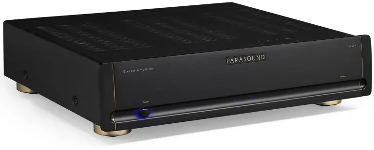
Rack Mounting Your Parasound JC 5
To mount the JC 5 into a 19″ wide equipment rack, you must first attach its two “L” shaped rack mount brackets (included). With its four feet removed, the JC 5 chassis and front panel height occupies four rack spaces (7″ or 176 mm). When mounting equipment below the JC 5, you will also need to allow about 1⁄8″ below the unit for the bottom chassis screws.
To attach the rack mount brackets:
- Remove the three screws from each side of the JC 5. These are arranged vertically, behind its front panel and in front of its first heatsink fin.
- Line up the three holes on each bracket with the three holes on the JC 5 and reinsert the screws.
- Make sure the screws are tight because they will support the entire weight of the JC 5 in the equipment rack.
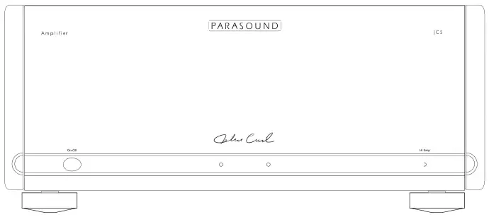
Note: Tighten each bolt just enough to keep the unit secure in the rack to avoid deforming the shoulder washers. Eliminating metal-to-metal contact reduces the likelihood of creating a ground loop that might introduce hum into your system.
A single standard rack space is 1-3⁄4″ (44mm) high in a 19″ wide equipment rack. This measurement standard was developed by the EIA (Electronic Industries Association) so manufacturers of electronic components and equipment racks could build products in standardized heights that would fit in a uniform space. Please call your Parasound dealer or Parasound Technical Services if you need additional advice about rack mounting the JC 5. Keep the above Note and Warning.
Audio Connections
Always disconnect the AC cord to your JC 5 before making or changing any input, output or trigger wire connections. Inserting or removing an input or output cable while the JC 5 is turned on can result in a blast of sound that can damage your loudspeakers. Make sure there is no strain or tension on any cables that could cause them to pull loose.
Audio Input Connections
Balanced XLR Input Jacks
In most systems balanced XLR connections will give you the best sound. If your stereo pre-amplifier has balanced XLR output jacks, we recommend that you connect them to the JC 5 XLR inputs. Refer to the Balanced and Unbalanced Lines in the Technically Speaking section for additional information about why we recommend using balanced lines.
Note: Using balanced XLR input connectors results in a 6 dB higher volume level compared with using the RCA input jacks. This is a noticeable increase.
Unbalanced RCA Input Jacks
Use these inputs if your pre-amplifier doesn’t have balanced XLR output connections or if you simply prefer to use unbalanced connections.
Balanced/Unbalanced Selector Switch
Place the switch in the position for the input type you will be using.
Note: The Balanced/Unbalanced switch is not an input selector. Its function is to optimize the signal to noise ratio for each type of input. You should not connect both the Balanced and Unbalanced jacks at the same time with the expectation of switching between two different devices such as a preamp and surround processor.
Balanced XLR Pin Configuration
The JC 5 XLR jacks conform to the industry standard of:
Pin 1: Ground Pin 2: Positive (+) Pin 3: Negative (–).
Loop Output Jacks
These jacks enable the incoming audio signal to pass along or “daisy chain” from the Left and Right
Input jacks to an additional amplifier or powered subwoofer. The Loop Out jacks are not affected by the Gain control settings. If you connect the preamp to the JC 5 with balanced XLR input jacks the RCA Loop Out jack functions normally.
Bridged Mode
Bridged operation configures the Left and Right channels to function as a single channel higher power amplifier to drive a single speaker. When a JC 5 is in Bridged Mode it provides far greater power output than the sum of its left and right channels’ power output. Please note that in bridged operation the minimum speaker impedance is 8 ohms. We do not recommend using the JC 5 with a 4 ohm speaker while set to bridged mode.
Bridged/Stereo Mode Selector Switch
Select Stereo for normal operation when the JC 5 will be powering two speakers. Only select Bridged when a JC 5 will be powering a single 8 ohm speaker.
Note: If the Bridge Mode switch is accidentally set to Bridge while you are using the JC 5 as a stereo amplifier the sound will become very weak and thin.
Speaker Connections for Bridged Mode
When operating in bridged mono mode a JC 5 should only power a single 8 ohm speaker.
Connect the speaker’s positive (+) speaker wire to the JC 5’s right channel positive (+) speaker terminal.
Connect the speaker’s negative (-) wire to the JC 5’s left channel positive (+) speaker terminal.
Correct + and – speaker polarity for bridged mode is shown below the JC 5 speaker terminals.
Bi-Amping is Often Superior to Bridged Mode
Bridging offers a massive power increase but It is often more power than your speakers need or can safely handle. Bi-amping is an alternative to bridging and many people report greater sonic improvements. Like bridging, bi-amping will require a JC 5 amplifier for each speaker.
Note: Bi-amping in this context is technically “passive bi-amping” so an external electronic crossover is not required. The speaker LF and HF terminals still connect to the speaker’s passive crossover circuits, the difference being that with passive bi-amping the LF and HF crossovers are powered separately.
Connecting Speaker Wires for Bi-amping
Bi-amping requires speakers with separate LF (Low Frequency) and HF (High Frequency) input terminals with removable metal straps or wires. (Some KEF speakers use a rotary switch to join or separate the HF and LF sections). The left channel of the first JC 5 will power the LF section of one speaker and this same JC 5’s right channel will power the HF section of the same speaker. The second JC 5 will connect the same way to the right channel speaker’s LF and HF inputs. When bi-amping both JC 5’s Bridged switches must be set to their Normal (Stereo) position.
Setting Up the Input Wires for Bi-amping
The JC 5 has an RCA Loop Output jack for each channel. These looping outputs allow the input signal from one channel to be daisy-chained to the other channel’s RCA Input jack. When bi-amping you will connect a standard RCA cable from the loop output of the Left channel to the Input RCA jack of the right channel. If you wish to connect your preamp with balanced XLR connections you will need to purchase a pair of XLR “Y” cables. You cannot use a combination of a balanced XLR input and RCA Loop Out to the other channel’s input because the balanced connections will play 6dB louder than the RCA connections.
Note: Both amplifiers left and right channel gain controls should be set at the same position.
Speaker Connections
Speaker Terminals
The JC 5 speaker terminals accept speaker wires terminated with banana plugs, spade connectors or up to 8 AWG bare wire.
Bare Speaker Wire End
If you plan to connect your speaker cables with bare wire ends, use a wire stripper to remove just enough insulation to expose a 1⁄2″ (13 mm) length of bare wire. You can insert the stripped wire into the hole that goes vertically through each terminal’s metal post. Before inserting the wire, twist its bare strands tightly to prevent any of the individual strands from making contact across the red plus and black minus speaker terminals. If you have a soldering iron, you can “tin” (apply a small amount of molten solder) to each stripped bare wire to prevent it from unraveling, fraying and oxidizing.
Correct Speaker Polarity is Important
Polarity refers to + and – connections. Speaker wires are coded with color, printing or a ridge on the insulation on one of the leads so you know which lead was connected to the + and – terminals at the other end. This coding will help you keep the + and – polarity consistent for all channels. If one speaker is wired with incorrect polarity it will significantly impair sound quality.
Speaker Wire Length and Gauge (thickness)
When selecting speaker wire, follow these guidelines:
- Keep the length of your speaker wire as short as possible.
- Use the thickest wire practical. For lengths greater than 50 feet, use speaker wire with an AWG (gauge) of 14 or lower. The smaller the AWG number, the thicker the wire.
Turn On Options
The setting of the rear panel Turn On Options switch determines how the amplifier turns on and off. Setting the Turn On Options switch to Audio or 12 V disables the JC 5’s front panel Power button. There are three positions for this switch:
Manual: When the Turn On Options switch is set to Manual the JC 5 is turned on and off manually only by pressing the Power button on its front panel every time you want to listen to music.
Audio: When the Turn On Options switch is set to the Audio position, the JC 5 will be turned on automatically when an audio signal is present at the L or R Input jacks. After the audio signal ceases the amplifier will remain on for about 10 minutes before shutting itself off. This prevents unintended turn-off during pauses in your music.
12 V Trigger: When the Turn On Options switch is set to its 12 V position, the JC 5 is turned on and off only with an external +9 V to +12 V DC voltage. When the external voltage ceases the amp will turn off within a few seconds. The 12 V turn on trigger circuit in the JC 5 requires a mere 5mA from the 12 V trigger source.
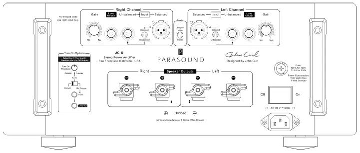
Turn On Threshold
This knob sets the audio signal level required for the JC 5 to automatically turn on when the Turn On Options switch is set to the Audio position. Fully counter-clockwise is the most sensitive setting and therefore is labeled “Quieter.” Fully clockwise requires a higher audio signal voltage and is therefore labeled “Louder.” In most systems the best results will be with the Turn On Threshold knob set at or towards the Quieter position. In some systems the JC 5 might turn itself on if there is a transient noise in the AC power line, even when an audio signal is not present. Similarly, the JC 5 might never shut off even after waiting more than 10 minutes. In this case, try rotating the knob towards the Louder position.
12 V In Jack
The JC 5 12 V input uses a 3.5 mm jack (mono). To use the 12 V trigger, insert the trigger wire plug into this jack and the plug at the wire’s other end into your preamplifier’s 12 V output jack. For your convenience we have included a 12 V trigger wire with mono 3.5 mm plugs at both ends. The JC 5 12 V trigger circuit draws a negligible 5 mA.
Note: If your preamplifier’s 12 V trigger output is terminal with + and – screws terminal, you can cut the 3.5 mm plug off one end of the included trigger wire and attach the bare wires to these terminals. The lead with the white stripe on it corresponds to the plug’s tip and the unmarked lead corresponds to the sleeve of the plug. The trigger plug tip is + (positive) and its sleeve – (negative).
12 V Loop Out Jack
The Trigger Out jack lets you loop or “daisy-chain” the incoming trigger voltage to an additional JC 5 or other component(s). The total load on your triggering device’s 12 V output is the sum of the trigger current drawn by each of the components you plan to loop together. Check the maximum capacity of your preamplifier’s trigger output so you do not overload it by connecting too many power amplifiers. Typical triggering devices are rated to handle 50 mA to 100 mA.
3.5 mm vs. 2.5 mm Jacks
Some other Parasound power amplifiers and preamplifiers might use a 2.5 mm “sub-mini” (mono) trigger jack. To use the JC 5 trigger with products that use a 2.5mm jack you will need a 3.5 mm to 2.5 mm mono adapter for one of the plugs on the included trigger wire.
Front Panel Operation
On-Off Button
Push once to turn on the JC 5. When the JC 5 is turned on the dim blue glow around the On-Off button will become brighter and the two blue channel indicators will illuminate. Push the button again to turn off the JC 5. The front panel On-Off button will be disabled when the Turn On Options switch is set to Audio or 12 V.
Whenever the JC 5 is turned on, the soft blue glow behind its On-Off button changes to red for a few seconds until its internal circuits have stabilized. Then the red glow is replaced by a brighter blue glow to indicate normal operation. If the glow remains red after turn on or while the amp is playing, it indicates activation of the JC 5’s protection circuits and no sound will be heard from the speakers.
The JC 5 protects itself from external conditions such as excessive heat, load impedance that is too low, or a short-circuited speaker connection or wire. After you correct the fault, the JC 5 will resume operation. If the JC 5 remains in “protection mode” after it has cooled down and you’ve confirmed there are no external faults, it could indicate an internal problem. Please contact Parasound’s Technical Service Department.
Channel Indicators
When the two blue channel indicators are lit, the JC 5 is operating normally. If one or both of the indicators does not light, even though the amp is turned on, there is a fault in your system. In the case of a fault first check that there is no short circuit with your speaker wire or speakers.
Hi Temp Indicator
This indicator is near the right side of the panel recess. It will glow red if any channel overheats. The On-Off button will also glow red if the JC 5 overheats. If such a condition occurs you must provide for better ventilation around the amplifier or check speakers for faulty operation that is causing the JC 5 to overheat.
Technically Speaking
Balanced and Unbalanced Lines
Recording and broadcast studios use balanced connections exclusively because of their inherent ability to reject noise and hum, thus assuring the best sound. Certain high quality preamplifiers and surround controllers built for residential use utilize balanced connections with XLR jacks for the same reasons. All Parasound Halo series power amplifiers have balanced inputs with XLR jacks so you can take full advantage of their inherent noise reduction capability and superior sound quality.
Unbalanced connections with RCA jacks are found on all home audio equipment. RCA jacks and two-conductor wires are less costly than the additional circuitry, higher priced XLR connectors and three-conductor differential balanced circuitry required for balanced connections.
In an unbalanced line, the positive audio signal is conducted through the center pin of an RCA plug and jack and the negative signal on the outer shield wire, which also functions as the ground connection. Unbalanced interconnect cables are vulnerable to hum from an AC line or other noise, such as broadcast RF (Radio Frequency), which can be reproduced through your loudspeakers. Since the unbalanced line’s ground also carries the audio signal, there is no way for the connected amplifier or preamplifier to distinguish between the audio signals you want and unwanted noise emanating from external sources.
Balanced lines are superior because they utilize separate conductors for the audio and the ground: two inner conductors carry the positive and negative audio signal, and a third outer wire connects the grounds and also shields the two signal conductors. When the positive and negative signals appear at the component receiving the signal they are equal, but 180 degrees out of phase with each other with respect to ground. To send and receive balanced signals requires special differential circuitry.
A differential input circuit amplifies only the difference between the positive and negative signals. For example, when a 1 Volt signal arrives at a balanced input stage, the differential input “sees” a positive +1 Volt minus a negative -1 Volt, or 2 Volts total. External hum and noise that somehow gets into a balanced line is common to both its positive and negative conductors with respect to ground. Therefore, it is canceled or rejected by the differential input circuit.
This phenomenon of rejecting noise signals common to both positive and negative conductors is called common mode rejection. Differential inputs are specified according to how well they reject signals common to both conductors. This is measured in dB and is called the common mode rejection ratio or CMRR.
Note: Balanced XLR connections result in a 6 dB higher gain, compared with the unbalanced RCA input jacks. In other words, the sound will be noticeably louder when you use balanced instead of unbalanced connections.
Ground Loops – Eliminating Hum and Buzz
Audible hum and buzzing noises in a system are usually related to issues with the component grounds. Ground (sometimes called “common”) is a point of reference for voltages in virtually all audio and video components. Ground is supposed to remain at zero volts while the audio signal voltage swings positive (voltage above ground) and negative (voltage below ground). If ground isn’t at zero, there can be an audible 60 Hz hum (or 50 Hz hum in regions with 50 Hz AC). The harmonics of these frequencies (120 Hz, 240 Hz, 480 Hz or 100 Hz, 200 Hz, 400 Hz) may add a raspy “buzzing” noise to the hum. The most common cause of a ground loop in an audio system is from cable TV. If disconnecting the cable line stops the hum then you might need a cable TV ground loop isolator.
The ideal of zero voltage ground for all the components in a system is practically impossible, because some resistance between the ground points of different components is inevitable. By keeping components close together with their power cords plugged into a common AC outlet or power strip, you’ll avoid the problems created by resistance in the house’s wiring.
Hum and buzz is also caused when unwanted voltage flows through multiple component ground points called ground loops. Here are three tips to avoid ground loops:
- Your Cable TV or Satellite receiver box might require a Cable TV Ground Isolator.
- Use balanced input cables with your Parasound JC 5. (See Balanced & Unbalanced Lines in this section).
- When rack mounting, always use the insulated “shoulder” washers on both the front and rear sides of the rack mount before attaching its bolts to the equipment rack rails. These break the ground loops caused by metal-to-metal contact between the rack, the components, and their rack-mount bolts. Extra washers are available from any rack manufacturer.
Parasound JC 5 Design Overview
Circuit Designed by John Curl
Parasound design consultant John Curl has been a legend among audiophiles and electronic engineers for decades. He pioneered measurements to correlate musical accuracy with the materials used in parts, worked with world-class touring companies, has designed highly coveted audio classics, including the original Mark Levinson JC-2, Denneson JC-80, Vendetta Phono Preamplifier, and CTC Blowtorch preamplifiers; master recorders for Wilson Audio and Mobile Fidelity; and the mixing consoles used in live concerts by The Grateful Dead and the Montreux Jazz Festival in Switzerland.
As our featured amplifier designer since 1990, he has created many products that have earned Parasound worldwide acclaim, including the Parasound Halo JC 1, JC 2 and JC 2 BP, JC 3, JC 3+ and JC 3 Jr.. John is particularly proud of what he and Parasound have accomplished together: “The circuits I design for Parasound are extremely sophisticated and are typical of products that are far more expensive. I can’t think of any other audio products that offer nearly as much bang for the buck.”
Parts Selection
Every part within the JC 5 is carefully chosen for its accuracy and reliability. Metal film resistors with 1% tolerance are selected for their precision and because their values don’t drift as they heat up during operation. Polypropylene and mica capacitors are used extensively for their superior linearity and low dielectric absorption. Semiconductors are selected for superior performance in their specific roles in the circuit. Gold has the best conductivity of any metal, so we use high quality gold-plated input connectors and speaker terminals. The double-sided circuit boards are FR4 glass epoxy for long-term durability. The chassis is made of heavy gauge steel to safely house the internal circuitry. This attention to detail when selecting parts makes the difference between a very good amplifier and an outstanding amplifier.
The Power Supply
The heart of the power supply is a 1.7 kVA toroid power transformer, chosen for its efficiency, low hum field, and high power rating. Encapsulating this massive power transformer in an epoxy-filled steel canister assures ultra-quiet performance.
The JC 5 power transformer employs multiple independent secondary windings so that each amplifier channel has its own power supply, assuring more than ample DC voltage at all times and under all conditions. It also reduces inter-channel crosstalk that can blur the sound and impair the correct sense of where instruments, dialogue and effects are positioned.
Each channel also has an independent power supply for its input stage. Their B+/B- voltage rails are even higher than the output stage voltage rails to prevent any chance of the driver stage voltage “sagging” when the amp is driven at high levels. This refinement greatly reduces measured and audible distortion.
Each channel’s +/- 98 Vdc output stage uses two premium quality 33,000uF Rubycon electrolytic filter capacitors, chosen for their low Equivalent Series Resistance (ESR), dielectric absorption and resistance to high temperature. In addition, these filter capacitors are bypassed with smaller polypropylene capacitors to reduce AC ripple in the DC supply and to further eliminate noise and interference that is generated in AC power lines from computers and other appliances in the home. The independent driver power supplies each employ Nichicon Gold Tune capacitors totaling 4,440uF per channel.
Relay-Bypassed Soft Start Circuit
When the JC 5 is first turned on, there is a significant amount of in-rush current required to charge the enormous power supply capacitors. We employ a NTC (negative temperature coefficient) thermistor order to slow down and suppress this in-rush current and to prevent nuisance tripping of a household circuit breaker. A thermistor cuts the in-rush current by approximately 50%. In a few seconds as it heats up to its operating temperature it it’s essentially a jumper wire with zero ohms resistance. However, the JC 5 goes one step further for this circuit. After the NTC resistor has done its job of suppressing in-rush current a relay with gold contacts automatically activates to jump across it to completely bypass it. This extra step insures that the thermistor does not restrict any current whatsoever when the JC 5 is in full operation.
Audio Circuit Path Topology
Parasound’s circuit topology is a hybrid of carefully chosen discrete transistors that result in superior performance at each stage. We use JFETs (Junction Field Effect Transistors) for the input voltage amplifier stage; MOSFETs (Metal Oxide Field Effect Transistors) for the drivers of a second voltage amplifier stage and bipolar transistors for the current amplifier output stage. Discrete transistors are more sonically accurate than integrated circuits commonly used by other brands.
Complementary Configuration
Each stage of amplification has transistors fed by the positive DC power supply and complementary transistors fed by the negative DC power supply. Thus, half of the devices amplify the positive half of the musical waveform while the other half of the devices amplify the negative half. This complementary topology is inherently linear, which reduces distortion and improves sonic accuracy.
The Input Stage
The JC 5’s input stage uses matched pairs of discrete JFETs arranged in a differential configuration. JFETs are ideal for the input stage because their inherently high impedance is unaffected by the impedance of source components. (Ordinary bi-polar transistors are low impedance devices) Differential configuration provides superior noise reduction. These precision input JFETs are also cascaded to produce the current necessary to drive the MOSFET drivers in the following stage.
The Driver Stage
The driver stage provides critical amplification for which we employ a complementary matched pair of MOSFETs selected for their tube-like sonic qualities. MOSFETs tend to generate less odd-order higher harmonic distortion than bipolar transistors. This is important because odd-order distortion sounds unnatural and fatiguing to the human ear, whereas even-order distortion is less offensive because it is consonant, rather than dissonant. Our MOSFET driver stage prevents the harshness and brittle sound so often found in other solid state amplifiers.
The Output Stage
The amplifier’s sonic characteristics are established by its input and driver stages. Now, the sole job of its output stage is to deliver the enormous current and voltage from its power supply to the speakers. Bipolar output transistors are better than MOSFETS in the output stage because of their higher safe operating area (SOA) and inherent ruggedness. Each channel’s output stage employs six pairs of high current (15-amp) bipolar transistors to insure long-term reliability, even with continuous high power operation and challenging speaker loads. Lightning-fast (60 MHz) transistors respond instantly to complex demands in the musical signal, virtually eliminating distortions that occur with “slower” transistors. Slew rate limiting and Transient Intermodulation Distortion (TIM) are simply not an issue in the JC 5.
Class A-A/B Operation
Pure class A operation provides the purest sound. However, an amplifier operating entirely in class A would be enormous, highly inefficient, and generate far too much heat. Class A/B combines the main advantage of Class A with the efficiency of Class B operation. It is a compromise that reduces the heat generated in pure class A operation and the higher-order odd harmonic distortions created in class B. In class AB, the driver and output stages are always partially turned on, which provides a nominal amount of pure class A operation. At higher power levels, when the musical waveform swings from positive to negative and vice versa, each bank of transistors is allowed to rest momentarily. This resting, or quiescent time, makes it possible to deliver high amounts of power without overheating. It also makes possible the use of passive cooling and avoid fans, whose noise can be heard over the music. The JC 5 input and driver stages employ pure Class A while its output stage operates with higher level of pure Class A power than many amplifiers selling for twice or three times its price. The result is less fatiguing, more natural sound.
Total Protection – DC Servos
Even a miniscule amount of Direct Current (DC) will burn out speakers without any warning. Every power amplifier must have some way to insure that DC from its power supply never reaches its + or – speaker terminals. Most amplifiers simply use adjustable trim controls to reduce their DC offset or capacitors to block DC. Unfortunately, trim controls can allow DC offset to increase over time, and even the most expensive capacitors in the audio signal path will “veil” sonic clarity and attenuate bass response.
Parasound power amplifiers incorporate ingenious and fast-acting DC servo circuits, completely eliminating the need for coupling and blocking capacitors. The JC 5 is direct (DC) coupled from its input jacks to its speaker terminals. This advanced circuitry never needs adjustment or maintenance. It operates outside the audio signal path to keep the DC offset at the output of the JC 5 at a constant 0.00 Vdc. The results are startling clarity, freedom from listening fatigue, and formidable bass response.
Total Protection – Relays
Each channel of the JC 5 has a high-quality protection relay with gold-plated contacts for long-term reliability. These relays function to protect either the amplifier, the speakers, or both. When the JC 5 is first powered on, these relays remain open for approximately three seconds as the positive and negative power supplies stabilize and reach equilibrium with no DC offset at the speaker terminals. This prevents annoying popping or other transient noises. Relay protection also prevents damage to your speakers in case of a catastrophic amplifier failure. Any amplifier that doesn’t use relay protection for its speaker outputs compromises the safety of the amplifier and your speakers.
Total Protection – Current Overload
Specialized current-sensing transistors are connected to the output stages of the JC 5 to constantly monitor the current flow through the output transistors. If the current drawn by this stage exceeds a predetermined safe level due to a load impedance below 1 ohm or a short circuit at the speaker terminals, the output relay will open immediately to prevent the output transistors or other parts from failing.
Total Protection – Fuses
In addition to the main fuse on the rear panel each channel of the amplifier has four internal fuses for the positive and negative DC voltage rails of input stage and two for the output stage These fuses provide backup protection in case the over-current protection does not work in time, or if an internal part fails. In the event of a part failure, these fuses halt operation to minimize damage to additional parts.
Problems and Remedies
Unit will not turn on
- Check the setting of the Turn On Options switch. (The front panel On-Off button will be disabled if this switch is set to Audio or 12 V)
- If using Audio Turn on, try increasing the sensitivity of the audio trigger by turning the audio threshold knob to the “Quieter” position.
- Check that the rear panel power switch is on and that the AC power is live.
No sound from speakers
- Check that input cables and speaker wires are secure at both ends.
- Make sure the pre-amplifier is switched to the correct input.
- Is the Hi-Temp light illuminated? Both blue channel indicators should be illuminated. Check for excessive temperature, short-circuited speaker wires, very low impedance speaker load, and inadequate ventilation.
Overheating
- Remove any nearby external sources of heat such other audio equipment or heaters.
- Increase ventilation around the JC 5.
- Check speakers for faults.
Background Hum or Hiss
- If you have cable or satellite TV, try disconnecting the incoming TV or satellite cable; if the hum is eliminated you will need a Cable TV Ground Isolator which can be purchased online.
- Light dimmers can cause noise in your audio system. Try turning lights that are controlled by dimmers all the way off. If the hum goes away the problem is electrical noise the dimmers introduce into your home’s AC power.
- Ground loops are also a common cause of hum and buzzing noise. Finding a ground loop requires a patient process of elimination. Unplug your source components one at a time. When the hum goes away you’ve identified the source of the ground loop. You might be able to stop the hum by attaching a wire from the chassis of the offending component to the chassis or ground screw of your pre-amplifier.
- Move audio cables and AC cords apart from each other.
- Try different routes for the audio cables and AC cords.
- Make sure plastic insulating shoulder washers are used if unit is rack mounted.
Are You Having Difficulty?
Repair or Service
Call your Parasound dealer first. If the dealer can’t help you with your problem we encourage you to call Parasound’s Technical Service Department at 415-397-7100, Monday – Friday, 8am – 4pm Pacific Time. We can suggest other diagnostic tests you can easily perform.
If we determine that your JC 5 should be returned to Parasound or an Authorized Parasound Warranty Center for inspection and possible servicing, we will provide the location of a warranty center near you or shipping instructions for the unit’s return to Parasound.
Before You Return Any Unit to Parasound for Service
Before you send your unit to Parasound, you will need to obtain a specific Return Authorization (RA) number and shipping instructions from Parasound’s Technical Department. The RA number must be clearly marked on the outer carton. Use the original factory packing materials and arrange adequate insurance to cover its value. You must include a copy of your purchase receipt, since this document establishes the validity of this unit’s warranty. Warranty repairs are only performed by Parasound or Parasound Authorized warranty centers when your purchase receipt is from a Parasound Authorized Dealer or Parasound Authorized Reseller.
Shipments Will Be Refused by Parasound Under the Following Conditions:
- Unit was sent without the Parasound-assigned RA number marked on the carton.
- Unit was sent in an unsuitable shipping carton and packing inserts and was likely to have been damaged in transit.
- Unit has inadequate packing materials and is likely to have been damaged in transit. Wrapping the JC 5 with bubble wrap will not protect it during shipment.
- Unit was shipped collect for shipping charges. We do not accept collect shipments.
- Unit was shipped via USPS, the US Postal Service. We do not accept USPS shipments.
- Unit was sent to an address other than the address instructed by our Technical Department.
Warranty Repair-USA
Please read the Parasound Limited Warranty carefully to understand the applicable rights and limitations. This section provides instructions for obtaining repairs, both for units covered under the Parasound Limited Warranty and for units or situations which are outside the Warranty. The complete warranty can be found at www.parasound.com.
Unit is not eligible for repair under the terms of the Parasound warranty if:
- Unit was not purchased from a Parasound Authorized Dealer.
- You do not have the original bill of sale receipt from the Parasound Authorized Dealer.
- You are not the original owner. The Parasound warranty is not transferable.
- Unit’s original serial number was removed, modified, or defaced.
- Unit shows evidence of abuse and/or misuse.
- Unit was altered in any way.
- A prior repair was attempted by an unauthorized repair station.
Warranty for products purchased outside the USA
Please refer to www.parasound.com
Chassis Illustration and Dimensions
Specifications
Power Output – Stereo Mode
- 400 watts x 2, 8 Ω both channels driven
- 600 watts x 2, 4 Ω both channels driven
Power Output – Bridged Mode
- 1200 watts x 1, 8 Ω
Bridged 4 Ω operation is not recommended
Power measurement parameters are at 120 VAC: 0.05% THD, RMS continuous power,
full audio band (20 Hz – 20 kHz)
Current Capacity
- 90 amps peak, per channel
Slew Rate
- 130 volts per microsecond
Frequency Response
- 5 Hz – 100 kHz, +0/-3 dB
- 20 Hz – 20 kHz, +0/-0.25 dB
Total Harmonic Distortion (THD)
- < 0.05 % at full power
- < 0.03 % at typical listening levels
IM Distortion
- < 0.04 %
TIM
- Unmeasurable
Inter-channel Crosstalk
- > 87 dB at 1 kHz
- > 72 dB at 20 kHz
Input Impedance
- Unbalanced: 33 kΩ
- Balanced: 66 kΩ,(33 kΩ per leg)
Total Gain
- 29 dB
Input Sensitivity for 28.28 V Output into 8 Ω
- Unbalanced: 1 V
- Balanced: 1 V per leg
S/N Ratio
- > 116 dB, input shorted, IHF A-weighted
- > 111 dB, input shorted, unweighted
Damping Factor
- 1200 at 20 k Hz
DC Trigger Requirements
- +9 Vdc to +12 Vdc, 5 mA
Audio Trigger Requirements
- 2 mV – 10 mV
XLR Pin Identification
- 1 = Ground (Shield)
- 2 = Positive
- 3 = Negative (Return)
Dimensions
- Width: 17-5⁄8″ (448 mm)
- Height without feet: 7-1⁄8″ (181 mm)
- Height with feet: 7-3/4″ ” (197 mm)
- Depth: 20″ (508 mm)
- Depth with cables: 21-1⁄2″ (546 mm)
Net Weight
- 73 lb. (33.1 kg)
Shipping Weight
- 90 lb. (40.8 kg)
Power Requirement
- Standby: 1 Watt
- Idle (no music playing): 225 Watts
- Typical Listening levels: 400 Watts
- Maximum: 1500 Watts
Specifications and features subject to change or improvement without notice. Copyright Parasound Product Inc., 2018, Rev. 1.0
Parasound Products, Inc. 2250 McKinnon Ave, San Francisco, CA 94124
415-397-7100 / Fax 415-397-0144 www.parasound.com
![]()