HALO Stereo Power Amplifier

Introduction
Your new Parasound Halo JC 5 power amplifier has been designed with the most advanced, proven class A/AB amplifier technology. The JC 5 is built to extremely strict quality and performance standards for which Parasound is renowned. We’re proud to offer you this exceptional audio component that will bring you many years of enjoyment and dependability. We designed your new Halo JC 5 Amplifier to perform at a higher level of sonic performance than you may have expected and we encourage you to read this entire manual to maximize your enjoyment. We wish you many years of listening enjoyment.
- The Parasound Staff
Keeping Records for Future Reference
Record the serial number located on the back panel or bottom of your JC 5 in the space below. Also note your Parasound Dealer’s name and telephone number. Your purchase receipt/bill of sale is required to determine if your JC 5 is eligible for Parasound warranty service. We recommend that you make an extra copy of your original purchase receipt/bill of sale and store it inside the JC 5’s carton.
Parasound JC 5 Amplifier Serial #: ______________ (5 digit number below the bar code)
Parasound Dealer: ___________________________________________________
Parasound Dealer Phone Number: ___________________
Date of Purchase: ______________________
Important Warranty Information
There is no Parasound warranty for this unit if it was not purchased from an Authorized.
Parasound Dealer. A list of Authorized Parasound Dealers and detailed warranty information is available at www.parasound.com or you can call 415-397-7100 between 8:30 am and 4 pm Pacific time. A missing or altered serial number could indicate that this unit was re-sold by an unauthorized dealer or is stolen merchandise. If this unit is missing its serial number or the serial number has been altered, you should return it to your dealer immediately for a full refund.
Investigate any claims made by a dealer who is not listed on our web site very carefully. Statements an unauthorized dealer makes regarding their own coverage or third party warranty coverage are undependable and misleading because unauthorized dealers and warranty companies lack the capability to make repairs or arrange for repairs of Parasound equipment.
Unauthorized dealers lack the capability to make repairs or arrange for repairs of Parasound equipment.
Unpacking Your JC 5 and Placement Guidelines
Unpacking Your JC 5
Carefully remove your JC 5 from its shipping carton and locate the enclosed accessories:
- AC power cord
- A 12V trigger wire for auto turn on. It has a mono 3.5 mm mini plug at each end.
While you are unpacking your JC 5, inspect it thoroughly for possible shipping damage and tell your Parasound dealer immediately if you find any evidence of shipping damage.
This would be a good time to make a copy of your sales receipt to store with the JC 5’s original packing.
Note: Please save and store both the inner and outer cartons and, most especially, the foam packing inserts to protect the JC 5 if you have to move it or ship it. You may wish to flatten the cardboard cartons to save room in storage after cutting the taped seams on the bottom flaps.
Placement Guidelines
The JC 5 will be easier to use and will last longer if you follow these simple guidelines:
- Place the JC 5 on a surface that will adequately support its substantial weight.
- Use input and output cables that are long enough to leave some slack; that will enable you to pull the JC 5 out of a cabinet to check or to change connections without inadvertently disconnecting cables.
- The JC 5 should never be placed in a completely enclosed cabinet.
- Place your JC 5 where you can route input and output signal cables as far as possible from any AC cords.
- Where input interconnects must cross AC cords they should do so only at a 90° right angle.
Ventilation Requirements
- Always position the JC 5 horizontally.
- The JC 5 should never be stacked directly above another power amplifier or directly below another component.
- Do not install the JC 5 in an unventilated equipment cabinet or compartment. Pockets of stagnant hot air can build up even in a cabinet with an open front and back. A ventilation fan is recommended to prevent “hot spots” in confined spaces.
AC Mains Voltage
NOTE: Before you plug this amplifier into an AC mains outlet:
If you live in a region with 220V-240V AC mains:
Plugging this amplifier into a 220V-240V AC mains outlet when the unit is internally configured for 115V and its main fuse rated for 115V operation will severely damage it and could put you at risk of personal injury. If you are unsure of the internal voltage setting for this amplifier you should have a qualified electronics technician inspect it and change it as required.
AC Voltage Re-configuring Technical Information
Parasound will provide technical information which pertains to the interior of this amplifier only to a qualified electronics technician. This restriction is for your safety as well as the correct functioning of your amplifier.
AC Voltage Warranty Exclusion
Amplifiers set for 115V which are damaged by 220V-240V are not covered under the Parasound Limited Warranty.
Before Making Any Audio Connections
Always turn off your JC 5 and disconnect the AC cord before making or changing any input, output or trigger wire connections. Inserting or removing an input or output cable while the JC 5 and your preamp are turned on can result in a blast of sound that can damage your loudspeakers.
AC Power Cord
The AC cord supplied with your JC 5 is a high quality IEC type cord. Please connect it directly to an AC wall outlet or power conditioner that is always “live.” If possible, plug your JC 5 into the same AC outlet that your pre-amplifier is plugged into. If different AC outlets are used for the JC 5 and other components, (including a TV
or video projector) the ground potential may be higher or lower between the outlets, resulting in audible hum.

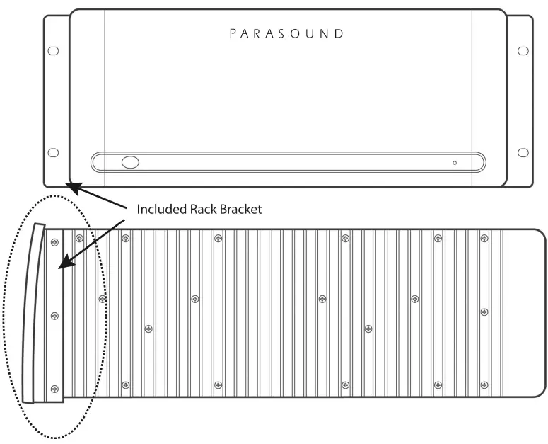
Rack Mounting Your Parasound JC 5
To mount the JC 5 into a 19″ wide equipment rack, you must first attach its two “L” shaped rack mount brackets (included). With its four feet removed, the JC 5 chassis and front panel height occupies four rack spaces (7″ or 176 mm). When mounting equipment below the JC 5, you will also need to allow about 1⁄8″ below the unit for the bottom chassis screws.
To attach the rack mount brackets:
- Remove the three screws from each side of the JC 5. These are arranged vertically, behind its front panel and in front of its first heatsink fin.
- Line up the three holes on each bracket with the three holes on the JC 5 and reinsert the screws.
- Make sure the screws are tight because they will support the entire weight of the JC 5 in the equipment rack.

Note: Tighten each bolt just enough to keep the unit secure in the rack to avoid deforming the shoulder washers. Eliminating metal-to-metal contact reduces the likelihood of creating a ground loop that might introduce hum into your system.
A single standard rack space is 1-3⁄4″ (44mm) high in a 19″ wide equipment rack. This measurement standard was developed by the EIA (Electronic Industries Association) so manufacturers of electronic components and equipment racks could build products in standardized heights that would fit in a uniform space. Please call your Parasound dealer or Parasound Technical Services if you need additional advice about rack mounting the JC 5. Keep the above Note and Warning.
Audio Connections
Always disconnect the AC cord to your JC 5 before making or changing any input, output or trigger wire connections. Inserting or removing an input or output cable while the JC 5 is turned on can result in a blast of sound that can damage your loudspeakers. Make sure there is no strain or tension on any cables that could cause them to pull loose.
Audio Input Connections
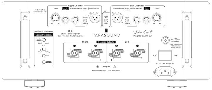
Balanced XLR Input Jacks
In most systems balanced XLR connections will give you the best sound. If your stereo pre-amplifier has balanced XLR output jacks, we recommend that you connect them to the JC 5 XLR inputs. Refer to the Balanced and Unbalanced Lines in the Technically Speaking section for additional information about why we recommend using balanced lines.
Note: Using balanced XLR input connectors results in a 6 dB higher volume level compared with using the RCA input jacks. This is a noticeable increase.
Unbalanced RCA Input Jacks
Use these inputs if your pre-amplifier doesn’t have balanced XLR output connections or if you simply prefer to use unbalanced connections.
Balanced/Unbalanced Selector Switch
Place the switch in the position for the input type you will be using.
Note: The Balanced/Unbalanced switch is not an input selector. Its function is to optimize the signal to noise ratio for each type of input. You should not connect both the Balanced and Unbalanced jacks at the same time with the expectation of switching between two different devices such as a preamp and surround processor.
Balanced XLR Pin Configuration
The JC 5 XLR jacks conform to the industry standard of:
Pin 1: Ground Pin 2: Positive (+) Pin 3: Negative (–).
Loop Output Jacks
These jacks enable the incoming audio signal to pass along or “daisy chain” from the Left and Right
Input jacks to an additional amplifier or powered subwoofer. The Loop Out jacks are not affected by the Gain control settings. If you connect the preamp to the JC 5 with balanced XLR input jacks the RCA Loop Out jack functions normally.
Bridged Mode
Bridged operation configures the Left and Right channels to function as a single channel higher power amplifier to drive a single speaker. When a JC 5 is in Bridged Mode it provides far greater power output than the sum of its left and right channels’ power output. Please note that in bridged operation the minimum speaker impedance is 8 ohms. We do not recommend using the JC 5 with a 4 ohm speaker while set to bridged mode.
Bridged/Stereo Mode Selector Switch
Select Stereo for normal operation when the JC 5 will be powering two speakers. Only select Bridged when a JC 5 will be powering a single 8 ohm speaker.
Note: If the Bridge Mode switch is accidentally set to Bridge while you are using the JC 5 as a stereo amplifier the sound will become very weak and thin.
Speaker Connections for Bridged Mode
When operating in bridged mono mode a JC 5 should only power a single 8 ohm speaker.
Connect the speaker’s positive (+) speaker wire to the JC 5’s right channel positive (+) speaker terminal.
Connect the speaker’s negative (-) wire to the JC 5’s left channel positive (+) speaker terminal.
Correct + and – speaker polarity for bridged mode is shown below the JC 5 speaker terminals.
Bi-Amping is Often Superior to Bridged Mode
Bridging offers a massive power increase but It is often more power than your speakers need or can safely handle. Bi-amping is an alternative to bridging and many people report greater sonic improvements. Like bridging, bi-amping will require a JC 5 amplifier for each speaker.
Note: Bi-amping in this context is technically “passive bi-amping” so an external electronic crossover is not required. The speaker LF and HF terminals still connect to the speaker’s passive crossover circuits, the difference being that with passive bi-amping the LF and HF crossovers are powered separately.
Connecting Speaker Wires for Bi-amping
Bi-amping requires speakers with separate LF (Low Frequency) and HF (High Frequency) input terminals with removable metal straps or wires. (Some KEF speakers use a rotary switch to join or separate the HF and LF sections). The left channel of the first JC 5 will power the LF section of one speaker and this same JC 5’s right channel will power the HF section of the same speaker. The second JC 5 will connect the same way to the right channel speaker’s LF and HF inputs. When bi-amping both JC 5’s Bridged switches must be set to their Normal (Stereo) position.
Setting Up the Input Wires for Bi-amping
The JC 5 has an RCA Loop Output jack for each channel. These looping outputs allow the input signal from one channel to be daisy-chained to the other channel’s RCA Input jack. When bi-amping you will connect a standard RCA cable from the loop output of the Left channel to the Input RCA jack of the right channel. If you wish to connect your preamp with balanced XLR connections you will need to purchase a pair of XLR “Y” cables. You cannot use a combination of a balanced XLR input and RCA Loop Out to the other channel’s input because the balanced connections will play 6dB louder than the RCA connections.
Note: Both amplifiers left and right channel gain controls should be set at the same position.
Speaker Connections
Speaker Terminals
The JC 5 speaker terminals accept speaker wires terminated with banana plugs, spade connectors or up to 8 AWG bare wire.
Bare Speaker Wire End
If you plan to connect your speaker cables with bare wire ends, use a wire stripper to remove just enough insulation to expose a 1⁄2″ (13 mm) length of bare wire. You can insert the stripped wire into the hole that goes vertically through each terminal’s metal post. Before inserting the wire, twist its bare strands tightly to prevent any of the individual strands from making contact across the red plus and black minus speaker terminals. If you have a soldering iron, you can “tin” (apply a small amount of molten solder) to each stripped bare wire to prevent it from unraveling, fraying and oxidizing.
Correct Speaker Polarity is Important
Polarity refers to + and – connections. Speaker wires are coded with color, printing or a ridge on the insulation on one of the leads so you know which lead was connected to the + and – terminals at the other end. This coding will help you keep the + and – polarity consistent for all channels. If one speaker is wired with incorrect polarity it will significantly impair sound quality.
Speaker Wire Length and Gauge (thickness)
When selecting speaker wire, follow these guidelines:
- Keep the length of your speaker wire as short as possible.
- Use the thickest wire practical. For lengths greater than 50 feet, use speaker wire with an AWG (gauge) of 14 or lower. The smaller the AWG number, the thicker the wire.
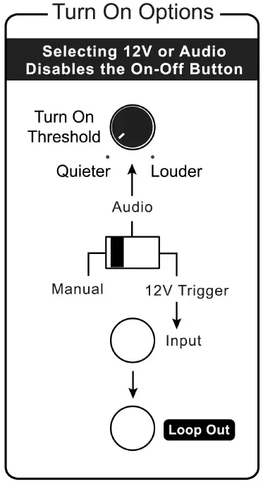
Turn On Options
The setting of the rear panel Turn On Options switch determines how the amplifier turns on and off. Setting the Turn On Options switch to Audio or 12 V disables the JC 5’s front panel Power button. There are three positions for this switch:
Manual: When the Turn On Options switch is set to Manual the JC 5 is turned on and off manually only by pressing the Power button on its front panel every time you want to listen to music.
Audio: When the Turn On Options switch is set to the Audio position, the JC 5 will be turned on automatically when an audio signal is present at the L or R Input jacks. After the audio signal ceases the amplifier will remain on for about 10 minutes before shutting itself off. This prevents unintended turn-off during pauses in your music.
12 V Trigger: When the Turn On Options switch is set to its 12 V position, the JC 5 is turned on and off only with an external +9 V to +12 V DC voltage. When the external voltage ceases the amp will turn off within a few seconds. The 12 V turn on trigger circuit in the JC 5 requires a mere 5mA from the 12 V trigger source.
Turn On Threshold
This knob sets the audio signal level required for the JC 5 to automatically turn on when the Turn On Options switch is set to the Audio position. Fully counter-clockwise is the most sensitive setting and therefore is labeled “Quieter.” Fully clockwise requires a higher audio signal voltage and is therefore labeled “Louder.” In most systems the best results will be with the Turn On Threshold knob set at or towards the Quieter position. In some systems the JC 5 might turn itself on if there is a transient noise in the AC power line, even when an audio signal is not present. Similarly, the JC 5 might never shut off even after waiting more than 10 minutes. In this case, try rotating the knob towards the Louder position.
12 V In Jack
The JC 5 12 V input uses a 3.5 mm jack (mono). To use the 12 V trigger, insert the trigger wire plug into this jack and the plug at the wire’s other end into your preamplifier’s 12 V output jack. For your convenience we have included a 12 V trigger wire with mono 3.5 mm plugs at both ends. The JC 5 12 V trigger circuit draws a negligible 5 mA.
Note: If your preamplifier’s 12 V trigger output is terminal with + and – screws terminal, you can cut the 3.5 mm plug off one end of the included trigger wire and attach the bare wires to these terminals. The lead with the white stripe on it corresponds to the plug’s tip and the unmarked lead corresponds to the sleeve of the plug. The trigger plug tip is + (positive) and its sleeve – (negative).
12 V Loop Out Jack
The Trigger Out jack lets you loop or “daisy-chain” the incoming trigger voltage to an additional JC 5 or other component(s). The total load on your triggering device’s 12 V output is the sum of the trigger current drawn by each of the components you plan to loop together. Check the maximum capacity of your preamplifier’s trigger output so you do not overload it by connecting too many power amplifiers. Typical triggering devices are rated to handle 50 mA to 100 mA.
3.5 mm vs. 2.5 mm Jacks
Some other Parasound power amplifiers and preamplifiers might use a 2.5 mm “sub-mini” (mono) trigger jack. To use the JC 5 trigger with products that use a 2.5mm jack you will need a 3.5 mm to 2.5 mm mono adapter for one of the plugs on the included trigger wire.
Front Panel Operation
On-Off Button
Push once to turn on the JC 5. When the JC 5 is turned on the dim blue glow around the On-Off button will become brighter and the two blue channel indicators will illuminate. Push the button again to turn off the JC 5. The front panel On-Off button will be disabled when the Turn On Options switch is set to Audio or 12 V.
Whenever the JC 5 is turned on, the soft blue glow behind its On-Off button changes to red for a few seconds until its internal circuits have stabilized. Then the red glow is replaced by a brighter blue glow to indicate normal operation. If the glow remains red after turn on or while the amp is playing, it indicates activation of the JC 5’s protection circuits and no sound will be heard from the speakers.
The JC 5 protects itself from external conditions such as excessive heat, load impedance that is too low, or a short-circuited speaker connection or wire. After you correct the fault, the JC 5 will resume operation. If the JC 5 remains in “protection mode” after it has cooled down and you’ve confirmed there are no external faults, it could indicate an internal problem. Please contact Parasound’s Technical Service Department.
Channel Indicators
When the two blue channel indicators are lit, the JC 5 is operating normally. If one or both of the indicators does not light, even though the amp is turned on, there is a fault in your system. In the case of a fault first check that there is no short circuit with your speaker wire or speakers.
Hi Temp Indicator
This indicator is near the right side of the panel recess. It will glow red if any channel overheats. The On-Off button will also glow red if the JC 5 overheats. If such a condition occurs you must provide for better ventilation around the amplifier or check speakers for faulty operation that is causing the JC 5 to overheat.
Technically Speaking
Balanced and Unbalanced Lines
Recording and broadcast studios use balanced connections exclusively because of their inherent ability to reject noise and hum, thus assuring the best sound. Certain high quality preamplifiers and surround controllers built for residential use utilize balanced connections with XLR jacks for the same reasons. All Parasound Halo series power amplifiers have balanced inputs with XLR jacks so you can take full advantage of their inherent noise reduction capability and superior sound quality.
Unbalanced connections with RCA jacks are found on all home audio equipment. RCA jacks and two-conductor wires are less costly than the additional circuitry, higher priced XLR connectors and three-conductor differential balanced circuitry required for balanced connections.
In an unbalanced line, the positive audio signal is conducted through the center pin of an RCA plug and jack and the negative signal on the outer shield wire, which also functions as the ground connection. Unbalanced interconnect cables are vulnerable to hum from an AC line or other noise, such as broadcast RF (Radio Frequency), which can be reproduced through your loudspeakers. Since the unbalanced line’s ground also carries the audio signal, there is no way for the connected amplifier or preamplifier to distinguish between the audio signals you want and unwanted noise emanating from external sources.
Balanced lines are superior because they utilize separate conductors for the audio and the ground: two inner conductors carry the positive and negative audio signal, and a third outer wire connects the grounds and also shields the two signal conductors. When the positive and negative signals appear at the component receiving the signal they are equal, but 180 degrees out of phase with each other with respect to ground. To send and receive balanced signals requires special differential circuitry.
A differential input circuit amplifies only the difference between the positive and negative signals. For example, when a 1 Volt signal arrives at a balanced input stage, the differential input “sees” a positive +1 Volt minus a negative -1 Volt, or 2 Volts total. External hum and noise that somehow gets into a balanced line is common to both its positive and negative conductors with respect to ground. Therefore, it is canceled or rejected by the differential input circuit.
This phenomenon of rejecting noise signals common to both positive and negative conductors is called common mode rejection. Differential inputs are specified according to how well they reject signals common to both conductors. This is measured in dB and is called the common mode rejection ratio or CMRR.
Note: Balanced XLR connections result in a 6 dB higher gain, compared with the unbalanced RCA input jacks. In other words, the sound will be noticeably louder when you use balanced instead of unbalanced connections.
Ground Loops – Eliminating Hum and Buzz
Audible hum and buzzing noises in a system are usually related to issues with the component grounds. Ground (sometimes called “common”) is a point of reference for voltages in virtually all audio and video components. Ground is supposed to remain at zero volts while the audio signal voltage swings positive (voltage above ground) and negative (voltage below ground). If ground isn’t at zero, there can be an audible 60 Hz hum (or 50 Hz hum in regions with 50 Hz AC). The harmonics of these frequencies (120 Hz, 240 Hz, 480 Hz or 100 Hz, 200 Hz, 400 Hz) may add a raspy “buzzing” noise to the hum. The most common cause of a ground loop in an audio system is from cable TV. If disconnecting the cable line stops the hum then you might need a cable TV ground loop isolator.
The ideal of zero voltage ground for all the components in a system is practically impossible, because some resistance between the ground points of different components is inevitable. By keeping components close together with their power cords plugged into a common AC outlet or power strip, you’ll avoid the problems created by resistance in the house’s wiring.
Hum and buzz is also caused when unwanted voltage flows through multiple component ground points called ground loops. Here are three tips to avoid ground loops:
- Your Cable TV or Satellite receiver box might require a Cable TV Ground Isolator.
- Use balanced input cables with your Parasound JC 5. (See Balanced & Unbalanced Lines in this section).
- When rack mounting, always use the insulated “shoulder” washers on both the front and rear sides of the rack mount before attaching its bolts to the equipment rack rails. These break the ground loops caused by metal-to-metal contact between the rack, the components, and their rack-mount bolts. Extra washers are available from any rack manufacturer.
Parasound JC 5 Design Overview
Circuit Designed by John Curl
Parasound design consultant John Curl has been a legend among audiophiles and electronic engineers for decades. He pioneered measurements to correlate musical accuracy with the materials used in parts, worked with world-class touring companies, has designed highly coveted audio classics, including the original Mark Levinson JC-2, Denneson JC-80, Vendetta Phono Preamplifier, and CTC Blowtorch preamplifiers; master recorders for Wilson Audio and Mobile Fidelity; and the mixing consoles used in live concerts by The Grateful Dead and the Montreux Jazz Festival in Switzerland.
As our featured amplifier designer since 1990, he has created many products that have earned Parasound worldwide acclaim, including the Parasound Halo JC 1, JC 2 and JC 2 BP, JC 3, JC 3+ and JC 3 Jr.. John is particularly proud of what he and Parasound have accomplished together: “The circuits I design for Parasound are extremely sophisticated and are typical of products that are far more expensive. I can’t think of any other audio products that offer nearly as much bang for the buck.”
Parts Selection
Every part within the JC 5 is carefully chosen for its accuracy and reliability. Metal film resistors with 1% tolerance are selected for their precision and because their values don’t drift as they heat up during operation. Polypropylene and mica capacitors are used extensively for their superior linearity and low dielectric absorption. Semiconductors are selected for superior performance in their specific roles in the circuit. Gold has the best conductivity of any metal, so we use high quality gold-plated input connectors and speaker terminals. The double-sided circuit boards are FR4 glass epoxy for long-term durability. The chassis is made of heavy gauge steel to safely house the internal circuitry. This attention to detail when selecting parts makes the difference between a very good amplifier and an outstanding amplifier.
The Power Supply
The heart of the power supply is a 1.7 kVA toroid power transformer, chosen for its efficiency, low hum field, and high power rating. Encapsulating this massive power transformer in an epoxy-filled steel canister assures ultra-quiet performance.
The JC 5 power transformer employs multiple independent secondary windings so that each amplifier channel has its own power supply, assuring more than ample DC voltage at all times and under all conditions. It also reduces inter-channel crosstalk that can blur the sound and impair the correct sense of where instruments, dialogue and effects are positioned.
Each channel also has an independent power supply for its input stage. Their B+/B- voltage rails are even higher than the output stage voltage rails to prevent any chance of the driver stage voltage “sagging” when the amp is driven at high levels. This refinement greatly reduces measured and audible distortion.
Each channel’s +/- 98 Vdc output stage uses two premium quality 33,000uF Rubycon electrolytic filter capacitors, chosen for their low Equivalent Series Resistance (ESR), dielectric absorption and resistance to high temperature. In addition, these filter capacitors are bypassed with smaller polypropylene capacitors to reduce AC ripple in the DC supply and to further eliminate noise and interference that is generated in AC power lines from computers and other appliances in the home. The independent driver power supplies each employ Nichicon Gold Tune capacitors totaling 4,440uF per channel.
Relay-Bypassed Soft Start Circuit
When the JC 5 is first turned on, there is a significant amount of in-rush current required to charge the enormous power supply capacitors. We employ a NTC (negative temperature coefficient) thermistor order to slow down and suppress this in-rush current and to prevent nuisance tripping of a household circuit breaker. A thermistor cuts the in-rush current by approximately 50%. In a few seconds as it heats up to its operating temperature it it’s essentially a jumper wire with zero ohms resistance. However, the JC 5 goes one step further for this circuit. After the NTC resistor has done its job of suppressing in-rush current a relay with gold contacts automatically activates to jump across it to completely bypass it. This extra step insures that the thermistor does not restrict any current whatsoever when the JC 5 is in full operation.
Audio Circuit Path Topology
Parasound’s circuit topology is a hybrid of carefully chosen discrete transistors that result in superior performance at each stage. We use JFETs (Junction Field Effect Transistors) for the input voltage amplifier stage; MOSFETs (Metal Oxide Field Effect Transistors) for the drivers of a second voltage amplifier stage and bipolar transistors for the current amplifier output stage. Discrete transistors are more sonically accurate than integrated circuits commonly used by other brands.
Complementary Configuration
Each stage of amplification has transistors fed by the positive DC power supply and complementary transistors fed by the negative DC power supply. Thus, half of the devices amplify the positive half of the musical waveform while the other half of the devices amplify the negative half. This complementary topology is inherently linear, which reduces distortion and improves sonic accuracy.
The Input Stage
The JC 5’s input stage uses matched pairs of discrete JFETs arranged in a differential configuration. JFETs are ideal for the input stage because their inherently high impedance is unaffected by the impedance of source components. (Ordinary bi-polar transistors are low impedance devices) Differential configuration provides superior noise reduction. These precision input JFETs are also cascaded to produce the current necessary to drive the MOSFET drivers in the following stage.
The Driver Stage
The driver stage provides critical amplification for which we employ a complementary matched pair of MOSFETs selected for their tube-like sonic qualities. MOSFETs tend to generate less odd-order higher harmonic distortion than bipolar transistors. This is important because odd-order distortion sounds unnatural and fatiguing to the human ear, whereas even-order distortion is less offensive because it is consonant, rather than dissonant. Our MOSFET driver stage prevents the harshness and brittle sound so often found in other solid state amplifiers.
The Output Stage
The amplifier’s sonic characteristics are established by its input and driver stages. Now, the sole job of its output stage is to deliver the enormous current and voltage from its power supply to the speakers. Bipolar output transistors are better than MOSFETS in the output stage because of their higher safe operating area (SOA) and inherent ruggedness. Each channel’s output stage employs six pairs of high current (15-amp) bipolar transistors to insure long-term reliability, even with continuous high power operation and challenging speaker loads. Lightning-fast (60 MHz) transistors respond instantly to complex demands in the musical signal, virtually eliminating distortions that occur with “slower” transistors. Slew rate limiting and Transient Intermodulation Distortion (TIM) are simply not an issue in the JC 5.
Class A-A/B Operation
Pure class A operation provides the purest sound. However, an amplifier operating entirely in class A would be enormous, highly inefficient, and generate far too much heat. Class A/B combines the main advantage of Class A with the efficiency of Class B operation. It is a compromise that reduces the heat generated in pure class A operation and the higher-order odd harmonic distortions created in class B. In class AB, the driver and output stages are always partially turned on, which provides a nominal amount of pure class A operation. At higher power levels, when the musical waveform swings from positive to negative and vice versa, each bank of transistors is allowed to rest momentarily. This resting, or quiescent time, makes it possible to deliver high amounts of power without overheating. It also makes possible the use of passive cooling and avoid fans, whose noise can be heard over the music. The JC 5 input and driver stages employ pure Class A while its output stage operates with higher level of pure Class A power than many amplifiers selling for twice or three times its price. The result is less fatiguing, more natural sound.
Total Protection – DC Servos
Even a miniscule amount of Direct Current (DC) will burn out speakers without any warning. Every power amplifier must have some way to insure that DC from its power supply never reaches its + or – speaker terminals. Most amplifiers simply use adjustable trim controls to reduce their DC offset or capacitors to block DC. Unfortunately, trim controls can allow DC offset to increase over time, and even the most expensive capacitors in the audio signal path will “veil” sonic clarity and attenuate bass response.
Parasound power amplifiers incorporate ingenious and fast-acting DC servo circuits, completely eliminating the need for coupling and blocking capacitors. The JC 5 is direct (DC) coupled from its input jacks to its speaker terminals. This advanced circuitry never needs adjustment or maintenance. It operates outside the audio signal path to keep the DC offset at the output of the JC 5 at a constant 0.00 Vdc. The results are startling clarity, freedom from listening fatigue, and formidable bass response.
Total Protection – Relays
Each channel of the JC 5 has a high-quality protection relay with gold-plated contacts for long-term reliability. These relays function to protect either the amplifier, the speakers, or both. When the JC 5 is first powered on, these relays remain open for approximately three seconds as the positive and negative power supplies stabilize and reach equilibrium with no DC offset at the speaker terminals. This prevents annoying popping or other transient noises. Relay protection also prevents damage to your speakers in case of a catastrophic amplifier failure. Any amplifier that doesn’t use relay protection for its speaker outputs compromises the safety of the amplifier and your speakers.
Total Protection – Current Overload
Specialized current-sensing transistors are connected to the output stages of the JC 5 to constantly monitor the current flow through the output transistors. If the current drawn by this stage exceeds a predetermined safe level due to a load impedance below 1 ohm or a short circuit at the speaker terminals, the output relay will open immediately to prevent the output transistors or other parts from failing.
Total Protection – Fuses
In addition to the main fuse on the rear panel each channel of the amplifier has four internal fuses for the positive and negative DC voltage rails of input stage and two for the output stage These fuses provide backup protection in case the over-current protection does not work in time, or if an internal part fails. In the event of a part failure, these fuses halt operation to minimize damage to additional parts.
Problems and Remedies
Unit will not turn on
- Check the setting of the Turn On Options switch. (The front panel On-Off button will be disabled if this switch is set to Audio or 12 V)
- If using Audio Turn on, try increasing the sensitivity of the audio trigger by turning the audio threshold knob to the “Quieter” position.
- Check that the rear panel power switch is on and that the AC power is live.
No sound from speakers
- Check that input cables and speaker wires are secure at both ends.
- Make sure the pre-amplifier is switched to the correct input.
- Is the Hi-Temp light illuminated? Both blue channel indicators should be illuminated. Check for excessive temperature, short-circuited speaker wires, very low impedance speaker load, and inadequate ventilation.
Overheating
- Remove any nearby external sources of heat such other audio equipment or heaters.
- Increase ventilation around the JC 5.
- Check speakers for faults.
Background Hum or Hiss
- If you have cable or satellite TV, try disconnecting the incoming TV or satellite cable; if the hum is eliminated you will need a Cable TV Ground Isolator which can be purchased online.
- Light dimmers can cause noise in your audio system. Try turning lights that are controlled by dimmers all the way off. If the hum goes away the problem is electrical noise the dimmers introduce into your home’s AC power.
- Ground loops are also a common cause of hum and buzzing noise. Finding a ground loop requires a patient process of elimination. Unplug your source components one at a time. When the hum goes away you’ve identified the source of the ground loop. You might be able to stop the hum by attaching a wire from the chassis of the offending component to the chassis or ground screw of your pre-amplifier.
- Move audio cables and AC cords apart from each other.
- Try different routes for the audio cables and AC cords.
- Make sure plastic insulating shoulder washers are used if unit is rack mounted.
Are You Having Difficulty?
Repair or Service
Call your Parasound dealer first. If the dealer can’t help you with your problem we encourage you to call Parasound’s Technical Service Department at 415-397-7100, Monday – Friday, 8am – 4pm Pacific Time. We can suggest other diagnostic tests you can easily perform.
If we determine that your JC 5 should be returned to Parasound or an Authorized Parasound Warranty Center for inspection and possible servicing, we will provide the location of a warranty center near you or shipping instructions for the unit’s return to Parasound.
Before You Return Any Unit to Parasound for Service
Before you send your unit to Parasound, you will need to obtain a specific Return Authorization (RA) number and shipping instructions from Parasound’s Technical Department. The RA number must be clearly marked on the outer carton. Use the original factory packing materials and arrange adequate insurance to cover its value. You must include a copy of your purchase receipt, since this document establishes the validity of this unit’s warranty. Warranty repairs are only performed by Parasound or Parasound Authorized warranty centers when your purchase receipt is from a Parasound Authorized Dealer or Parasound Authorized Reseller.
Shipments Will Be Refused by Parasound Under the Following Conditions:
- Unit was sent without the Parasound-assigned RA number marked on the carton.
- Unit was sent in an unsuitable shipping carton and packing inserts and was likely to have been damaged in transit.
- Unit has inadequate packing materials and is likely to have been damaged in transit. Wrapping the JC 5 with bubble wrap will not protect it during shipment.
- Unit was shipped collect for shipping charges. We do not accept collect shipments.
- Unit was shipped via USPS, the US Postal Service. We do not accept USPS shipments.
- Unit was sent to an address other than the address instructed by our Technical Department.
Warranty Repair-USA
Please read the Parasound Limited Warranty carefully to understand the applicable rights and limitations. This section provides instructions for obtaining repairs, both for units covered under the Parasound Limited Warranty and for units or situations which are outside the Warranty. The complete warranty can be found at www.parasound.com.
Unit is not eligible for repair under the terms of the Parasound warranty if:
- Unit was not purchased from a Parasound Authorized Dealer.
- You do not have the original bill of sale receipt from the Parasound Authorized Dealer.
- You are not the original owner. The Parasound warranty is not transferable.
- Unit’s original serial number was removed, modified, or defaced.
- Unit shows evidence of abuse and/or misuse.
- Unit was altered in any way.
- A prior repair was attempted by an unauthorized repair station.
Warranty for products purchased outside the USA
Please refer to www.parasound.com
Chassis Illustration and Dimensions
Specifications
Power Output – Stereo Mode
- 400 watts x 2, 8 Ω both channels driven
- 600 watts x 2, 4 Ω both channels driven
Power Output – Bridged Mode
- 1200 watts x 1, 8 Ω
Bridged 4 Ω operation is not recommended
Power measurement parameters are at 120 VAC: 0.05% THD, RMS continuous power,
full audio band (20 Hz – 20 kHz)
Current Capacity
- 90 amps peak, per channel
Slew Rate
- 130 volts per microsecond
Frequency Response
- 5 Hz – 100 kHz, +0/-3 dB
- 20 Hz – 20 kHz, +0/-0.25 dB
Total Harmonic Distortion (THD)
- < 0.05 % at full power
- < 0.03 % at typical listening levels
IM Distortion
- < 0.04 %
TIM
- Unmeasurable
Inter-channel Crosstalk
- > 87 dB at 1 kHz
- > 72 dB at 20 kHz
Input Impedance
- Unbalanced: 33 kΩ
- Balanced: 66 kΩ,(33 kΩ per leg)
Total Gain
- 29 dB
Input Sensitivity for 28.28 V Output into 8 Ω
- Unbalanced: 1 V
- Balanced: 1 V per leg
S/N Ratio
- > 116 dB, input shorted, IHF A-weighted
- > 111 dB, input shorted, unweighted
Damping Factor
- 1200 at 20 k Hz
DC Trigger Requirements
- +9 Vdc to +12 Vdc, 5 mA
Audio Trigger Requirements
- 2 mV – 10 mV
XLR Pin Identification
- 1 = Ground (Shield)
- 2 = Positive
- 3 = Negative (Return)
Dimensions
- Width: 17-5⁄8″ (448 mm)
- Height without feet: 7-1⁄8″ (181 mm)
- Height with feet: 7-3/4″ ” (197 mm)
- Depth: 20″ (508 mm)
- Depth with cables: 21-1⁄2″ (546 mm)
Net Weight
- 73 lb. (33.1 kg)
Shipping Weight
- 90 lb. (40.8 kg)
Power Requirement
- Standby: 1 Watt
- Idle (no music playing): 225 Watts
- Typical Listening levels: 400 Watts
- Maximum: 1500 Watts
Specifications and features subject to change or improvement without notice. Copyright Parasound Product Inc., 2018, Rev. 1.0
Parasound Products, Inc. 2250 McKinnon Ave, San Francisco, CA 94124
415-397-7100 / Fax 415-397-0144 www.parasound.com
![]()