
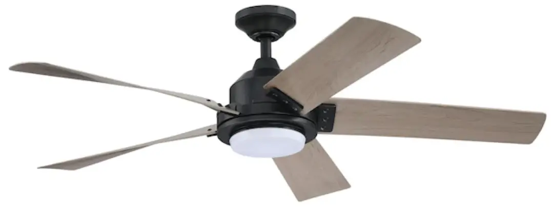
Harbor Breeze HTD20004 Berkshire Ceiling Fan User Manual
SAFETY PRECAUTIONS
Please observe the following general safety precautions carefully before and during all phases of handling, installation, removal, operation and maintenance of this product. Failure to comply with these precautions violates safety standards of design, manufacture and intended use of the product.
We assumes no liability for customer’s failure to comply with these requirements.
SAFETY WARNINGS
- Read all instructions and safety information. Review assembly diagrams provided before installing your new ceiling fan.
- This remote controller must be installed according to local authority regulations.
- This product is not intended for use by persons (including children) with reduced physical, sensory or mental capabilities, or lack of experience and knowledge, unless they have been given supervision or instruction concerning use of the appliance by a person responsible for their safety.
- Young children should be supervised to ensure that they do not play with the appliance.
- All electrical works must only be undertaken after disconnection of the power by removing fuses or turning off the circuit breaker, to ensure all pole isolation of the electrical supply.
- Do not use outdoors where it could be exposed to water or moisture.
- This product is for indoor use only.
- This product requires 120 Vac 60 Hz power supply.
- This product is to be used only for controlling a ceiling fan with an A.C. (Alternating Current) motor.
- Do not pull or cut short lead wires.
- Do not drop or bump the remote controller set.
- Do not use this remote controller in conjunction with any variable (rheostat) wall controller.
- Do not use the remote controller transmitter (handset) with any other receiver.
- Keep battery out of reach of children.
- This manual is not intended to instruct or assist untrained or unqualified persons to install this remote controller.
- It is the responsibility of qualified, licensed installer and user to apply common sense and care at all times during installation and operation.
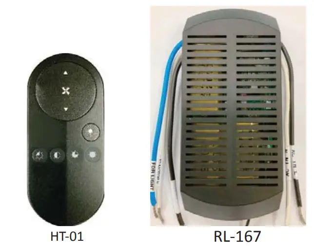
6 Speeds Fan Controller
INSTALLATION INSTRUCTIONS
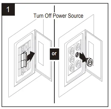
Make sure electricity is turned off at the main power box before commencing work. Turn off the power by removing fuse or turning off circuit breaker before installing remote controller.
READ BEFORE INSTALLATION
- Power supply to input wires of remote controller receiver must be connected through an isolation switch (e.g. wall switch).
- Install remote controller receiver inside ceiling fan canopy to ensure proper protection.
- Set ceiling fan speed control rotary switch (if any) to HIGH setting and control switch for light kit (if any) to ON position before operating remote control functions.
- For ceiling fan with pull chain switches, set pull chain switches accordingly so that ceiling fan speed setting is at HIGH and fan light setting (if any) is at ON position before operating remote control functions.
- Battery will weaken over time and should be replaced before leaking takes place as this will damage the transmitter. Dispose of used battery properly.
- If remote controller is to be used for controlling a ceiling fan (i) with a low profile (hugger) design, or (ii) that has a smaller hanging bracket, then you should make sure the hanging bracket will fit remote controller receiver. Otherwise, if the receiver cannot be inserted into the hanging bracket due to dimension limitations or because there is no hanging bracket as may be in the case of a low profile (hugger design) ceiling fan, then the receiver can be enclosed in an Electrical Insulation Box (installation must comply to Australian wiring regulations) and placed in the ceiling. Electrical Insulation Box is not supplied. In this case, remember to draw the antenna / aerial wire away from the insulation box through a small hole.
HOW TO INSTALL REMOTE CONTROLLER ID CODE LEARNING
- Each transmitter (handset) of this remote controller carries a unique Identity Code (ID Code) to facilitate communication between paired devices. The ID Code is set by factory and is not user changeable. The length of ID Code allows up to a million different code combinations, enabling independent control of multiple fans installed within a close proximity. A remote receiver must undergo an “ID code learning” process before it recognises and can communicate with the remote handset. However, you will be required to perform an “ID code learning” process manually under these circumstances:
- When you have multiple fans installed within a close proximity and want to control all fans using a same remote transmitter.
Note: Each fan requires its own receiver
- When your remote controller is not responding (make sure battery is not flat)
- After you have replaced a faulty transmitter or receiver with a new one.
Otherwise the remote controller will not work. To perform this process manually, follow below steps:
INSTRUCTION:
Turning on the AC power to the remote receiver, press and hold the transmitter “ FAN ” button for 5 seconds until the receiver beeps to indicate the code learning process had been completed. This operation must be completed within 1 minute after turning on the AC power.
NOTE:
- If the fan is not responding to the transmitter, turn off the power to the receiver and repeat the INSTRUCTION.
- Check that battery is installed.
- Remove the battery if not used for long period of time to prevent damage to the handset.
| Make sure power supply is cut off before removing fan canopy | 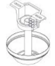 |
| Think about best orientation of remote receiver inside fan canopy. Connect receiver’s input and output wires in accordance to wiring diagram provided. Note: Isolation switch must be installed. | 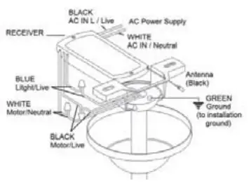 |
| Tidy up wires and re-install fan canopy. Make sure not to break any wire connection | 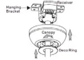 |
FUNCTIONS
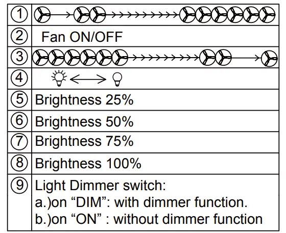
FAN CONTROL
FAN ON/OFF: Press to turning fan on or off SPEED: Press Up or Down key to set 1-6 fan speed .
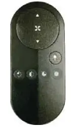
LIGHT SETTING:
Before first use, set the slide switch position to “on” side if the light without dimming funtion. set the slide switch position to “DIM” side if the light with dimming funtion.
NOTICE:
If the light is not dimmable
DO NOT slide the switch to right position, It may cause the light to flicker
LIGHT CONTROL
Press light key to Turing Light On or Off Press and hold light key to dimming light brightness or you can press 4 instant keys to set the brightness at 25% 50% 75% 100%
Federal Communication Commission Interference Statement
This equipment has been tested and found to comply with the limits for a Class B digital device, pursuant to Part 15 of the FCC Rules. These limits are designed to provide reasonable protection against harmful interference in a residential installation. This equipment generates, uses, and can radiate radio frequency energy and, if not installed and used in accordance with the instructions, may cause harmful interference to radio communications. However, there is no guarantee that interference will not occur in a particular installation. If this equipment does cause harmful interference to radio or television reception, which can be determined by turning the equipment off and on, the user is encouraged to try to correct the interference by one or more of the following measures:
- Reorient or relocate the receiving antenna.
- Increase the separation between the equipment and receiver.
- Connect the equipment into an outlet on a circuit different from that to which the receiver is connected.
- Consult the dealer or an experienced radio/TV technician for help.
FCC Caution:
This device complies with Part 15 of the FCC Rules. Operation is subject to the
following two conditions: (1) This device may not cause harmful interference, and (2) this device must accept any interference received, including interference that may cause undesired operation.
This device complies with Industry Canada licence-exempt RSS standard(s).
Operation is subject to the following two conditions:
- This device may not cause interference, and
- This device must accept any interference, including interference that may cause undesired operation of the device.
This device complies with RSS 210 of Industry Canada. This Class B device meets all the requirements of the Canadian interference-causing equipment regulations
PACKAGE CONTENTS
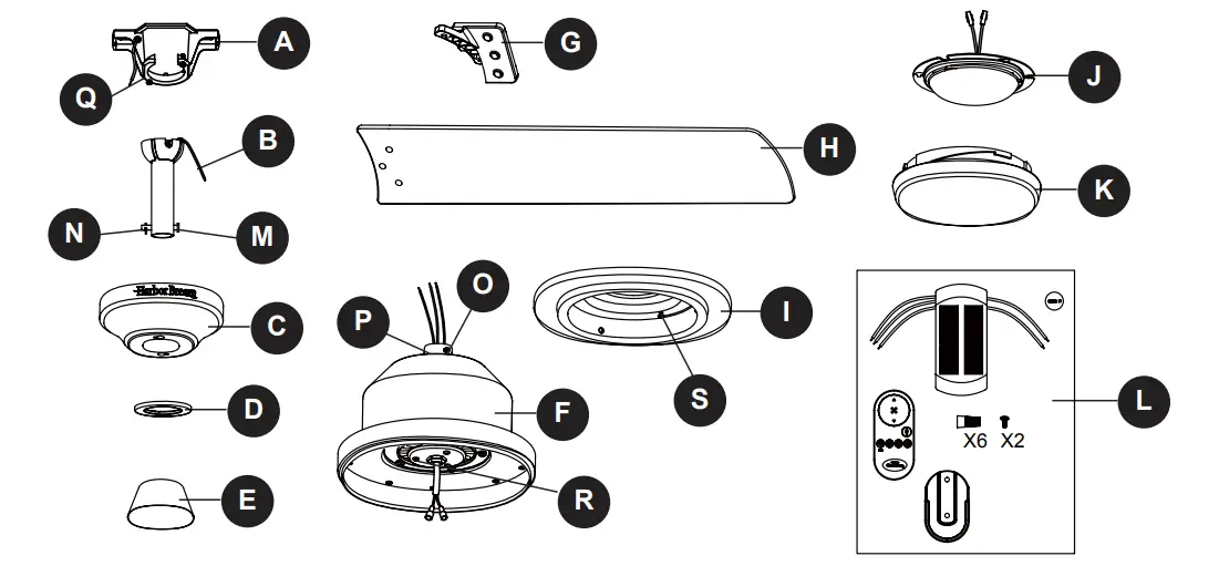
| PART | DESCRIPTION | QUANTITY |
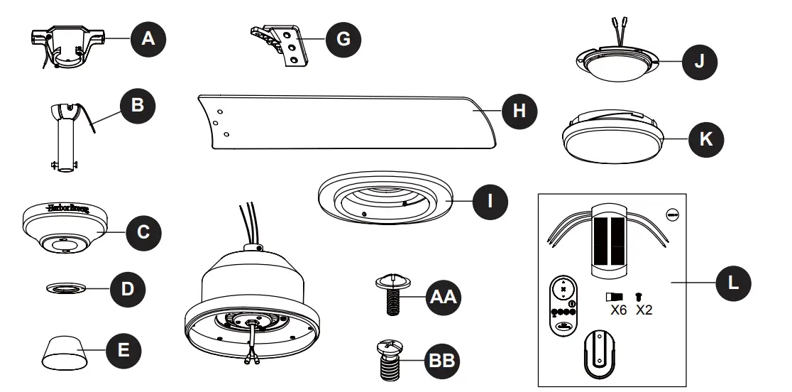
| A | Mounting Bracket | 1 |
| B | Downrod Assembly | 1 |
| C | Canopy | 1 |
| D | Canopy Cover | 1 |
| 1 | ||
| F | Motor Housing | 1 |
| G | Blade Arm | 5 |
| H | Blade | 5 |
| I | Switch Housing | 1 |
| J | Light Kit | 1 |
| K | Bowl | 1 |
| L | Remote Unit | 1 |
| M | Clevis Pin (Preassembled on Downrod Assembly (B) | 1 |
| N | Hairpin Clip (preassembled on Downrod Assembly (B) | 1 |
| O | Coupling Screw (preassembled on Coupling (P)) | 2 |
| P | Coupling (preassembled on Motor Housing (F)) | 1 |
| Q | Mounting Bracket Screw (preassembled on Mounting Bracket (A)) | 2 |
| R | Mounting Screw (preassembled on Motor Housing (F)) | 3 |
| S | Switch Housing Screw (preassembled on Switch Housing (I)) | 3 |
HARDWARE CONTENTS
HARDWARE CONTENTS
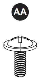
- Blade Screw Qty.15+1 extra
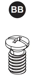
- Blade Arm Screw Qty.10+1 extra
SAFETY INFORMATION
READ AND SAVE THESE INSTRUCTIONS
Please read and understand this entire manual before attempting to assemble, operate or install the product.
- All electrical connections must comply with local codes, ordinances or the National Electric Code (NEC). Contact your municipal building department to inquire about your local codes, permits and/or inspections.
- Turn off electricity at main fuse box (or circuit breaker box) before beginning installation by removing fuse or by switching off circuit breaker.
- Do not connect this fixture to an electrical system that does not provide a means for equipment grounding. Never use a fixture in a two-wire system that is not grounded.
- If you are not sure your lighting system has a grounding means, do not attempt to install this fixture. Contact a qualified, licensed electrician for information regarding proper grounding methods as required by the local electrical code in your area.
- Make sure the installation site you choose allows a minimum clearance of 7 ft. from the blades to the floor and at least 30 in. from the ends of the blades to any obstruction.
- If a dimmer control switch is used with this fixture, obtain professional advice to determine the correct type and electrical rating required.
- The lighting fixture must be positioned so there is at least 1.64 ft. between the bulb and any illuminated surface.
- For supply connections, if the conductor of a fan is identified as a grounded conductor, then it should be connected to a grounded conductor power supply. If the conductor of a fan is identified as an ungrounded conductor, then it should be connected to an ungrounded conductor power supply. If the conductor of a fan is identified for equipment grounding, then it should be connected to an equipment-grounding conductor.
 DANGER
- Installing a fixture into an electrical system without a proper grounding means could allow metal parts of the fixture to carry electrical currents. If any of the fixture wires, wire connections or splices are broken, cut or loose during the mounting or normal operation of the fixture, under such conditon, anyone coming in contact with the fixture is subject to electrical shock, which could cause serious injury or death.
- Connection of the bare or green fixture ground wire to the black or white house wires may allow metal parts of the fixture to carry electrical currents. Under this condition anyone coming in contact with the fixture will receive electrical shock, which could cause serious injury or death.
- Be careful not to damage or cut the wire insulation (covering) during fixture installation. Do not permit wires to have contact with any surface having a sharp edge. Doing so may damage or cut the wire insulation, which could cause serious injury or death from electric shock.
WARNING
- Risk of fire. Most dwellings built before 1985 have supply wire rated for 140°F. Consult a qualified electrician before installation.
- To reduce the risk of fire or electric shock, do not use this fan with any solid state fan speed device or variable speed control.
- To reduce the risk of personal injury, do not bend the blade brackets when installing the brackets, balancing or cleaning the fan.
- Do not insert foreign objects in between rotating fan blades.
- Do not install or use the fan if any part is damaged or missing.
- To reduce the risk of fire, electric shock or personal injury, mount to metal outlet box marked ‘ACCEPTABLE FOR FAN SUPPORT OF 35 LBS OR LESS’ and use mounting screws provided with the outlet box and/or support directly from building structure. Most outlet boxes commonly used for the support of luminaries are not acceptable for fan support and may need to be replaced. Consult a qualified electrician if in doubt.
- Before servicing or cleaning the unit, switch power off at the service panel and lock the service disconnecting means to prevent power from being switched on accidentally. When the service disconnecting means cannot be locked, securely fasten a prominent warning device, such as a tag, to the service panel.
- Chemical Burn Hazard. Keep batteries away from children. This remote contains a lithium button cell battery. If a new or used lithium button/coin cell battery is swallowed or enters the body, it can cause severe internal burns and can lead to death in as little as 2 hours. Always completely secure the battery compartment. If the battery compartment does not close securely, stop using the product, remove the batteries, and keep it away from children. If you think batteries might have been swallowed or placed inside any part of the body, seek immediate medical attention. Dispose of cells properly and keep away from children. Even used cells may cause injury.
CAUTION
- Do not use bulbs having a wattage greater than the maximum value stated on the fixture and in this manual. Using a higher wattage bulb than specified will increase fixture temperature and increase risk of fire.
PREPARATION
Before beginning assembly of product, make sure all parts are present. Compare parts with package contents list and hardware contents list. If any part is missing or damaged, do not attempt to assemble the product.
Estimated Assembly Time: 45 minutes
Tools Required for Assembly (not included): Phillips Screwdriver, Step Ladder, Tape, Pliers and Wire Cutters.
INITIAL INSTALLATION INSTRUCTIONS
- Turn off circuit breakers and wall switch to the fan supply line leads.
DANGER: Failure to disconnect power supply prior to installation may result in serious injury or death.
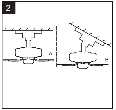
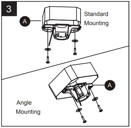
- Choose the desired mounting method:
A. Standard Mounting:
Standard mounting is best suited for ceilings 8 feet. or higher. For taller ceilings you may want to use a longer downrod (not included).
B. Angle Mounting:
Angle-style mounting is best suited for angled or vaulted ceilings. A longer downrod is sometimes necessary to ensure proper blade clearance. If using the angle mount, make sure the ceiling angle is not steeper than 20°.
For ALL mounting options, there must be at least 30 inches from the blade tip to nearest wall. Also, ensure there is 7 feet from the bottom edge of the blade to the floor.
- Check existing outlet box (not included) to ensure it is securely fastened to at least two points in a structural ceiling member and can support the full weight of the fan. Once verified, install mounting bracket (A) to the outlet box using the screws and washers provided with the outlet box.
DANGER: A loose outlet box can cause the fan to wobble and increase the fan’s potential to fall, which could result in serious injury or death.
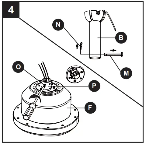
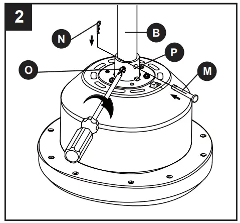
Note: If using the angle mount, make sure open end of mounting bracket (A) points toward the ceiling. - Loosen the two coupling screws(O) preassembled in coupling (P), but do not remove them.
Remove the hairpin clip (N) and clevis pin (M) from the downrod assembly (B). Retain for later use.
Note: Make sure to keep loose hardware separate to avoid confusion during installation.
STANDARD/ANGLE-MOUNTING INSTRUCTIONS
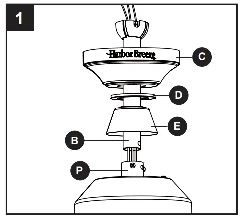
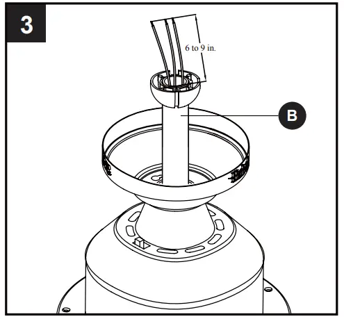
- Place downrod assembly (B) through canopy (C), canopy cover (D) and coupling cover (E).Feed power wires from motor housing (F) through downrod assembly (B), then insert downrod assembly (B) into the coupling (P) on motor housing (F).
- Align the hole on downrod assembly (B) to hole on coupling (P), then re-install clevis pin (M). Re-attach hairpin clip (N) into clevis pin (M) until it snaps into place, then tighten the two previously loosened coupling screws (O).
- Cut off excess fixture wires, leaving approximately 6 to 9 inches above the top of the downrod assembly (B). Strip 1/2 inch of insulation from the end of each fixture wire.
CAUTION: Ensure all screws are tight before moving onto the next step - Carefully lift the assembly and rest the hanger ball of downrod assembly (B) on the mounting bracket (A) attached to the outlet box. Be sure the groove in the hanger ball is lined up with the tab on the mounting bracket (A). This will allow for hands-free wiring.
Proceed to WIRING.
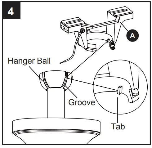
DANGER: Be careful when aligning the tab to the groove ! If not fully engaged, there is a possibility of the fan falling, which may result in serious injury or death.
WIRING INSTRUCTIONS
WARNING: To avoid possible electrical shock, be sure electricity is turned off at the main fuse box before hanging.
WARNING: If you are not sure if the outlet box is grounded, contact a licensed electrician for advice, as it must be grounded for safe operation.
WARNING: If house wires are different colors than referred to in the following steps, stop immediately. A professional electrician is recommended to determine proper wiring.
WARNING: If you feel that you do not have enough electrical wiring knowledge or experience, have your fan installed by a licensed electrician.
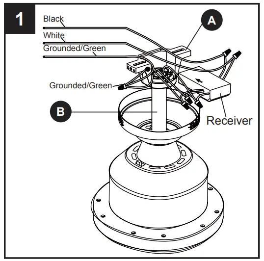
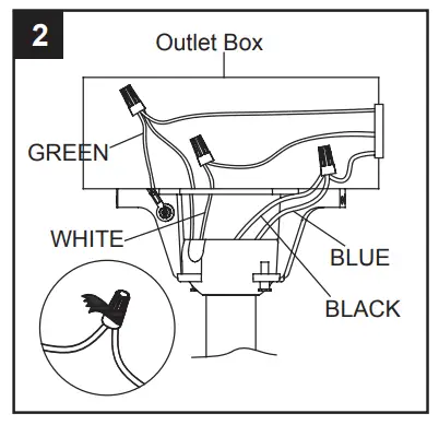
Follow steps below to wiring your fan, once wiring step has been completed, slide the wired receiver in between the mounting bracket (A) and the top of the downrod ball (B) with the flat side of the receiver facing the ceiling.
- Connect WHITE wire from the fan to WHITE wire marked TO MOTOR N from the receiver.
- Connect BLUE wire from the fan to BLUE wire marked FOR LIGHT from the receiver.
- Connect BLACK wire from the fan to BLACK wire marked TO MOTOR L from the receiver.
- Connect BLACK wire from the outlet box to BLACK wire marked AC IN L from the receiver.
- Connect WHITE wire from the outlet box to WHITE wire marked AC IN N from the receiver.
- Connect GROUND (GREEN) wires from mounting bracket and downrod ball, to GROUND (GREEN or BARE COPPER) from house.
Hardware Used
Wire Connector x 6
Wrap electrical tape (not included) around each wire connector and make sure no bare wire or wire strands are visible after making connections. Then, turn wires upward and carefully push them into the outlet box; make sure the WHITE and GREEN connections are on one side and the BLACK connections are on the other side.
FINAL INSTALLATION INSTRUCTIONS
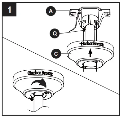
- Loosen (but do not remove) the two preassembled mounting screws (Q) on mounting bracket (A) that align with the slotted holes on canopy (C). Lift canopy (C) up so slotted holes engage loosened screw heads on mounting bracket (A), then twist canopy (C) clockwise, then tighten all screws securely
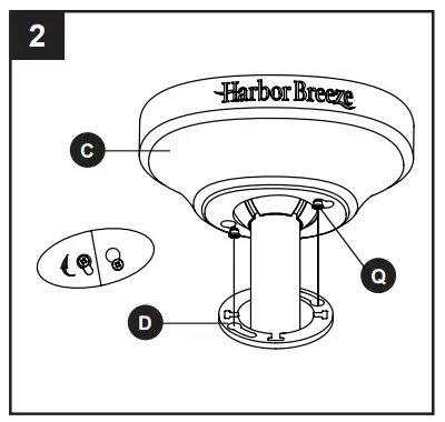
- Raise canopy cover (D) over the mounting screws (Q) visible in canopy (C). Rotate canopy cover (D) clockwise until it locks into place. You may need to adjust the mounting screws (Q) until the canopy (C) and canopy cover (D) have a snug fit.
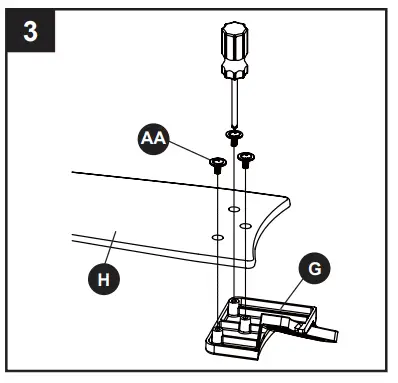
- Place the blade (H) over the blade arm (G), make sure the bottom edge of blade(H) is fully seated against the blade arm (G), securely tighten the blade (H) to blade arm with three (3) blade screws(AA). Repeat or remaining blades.
Hardware Used

- Attach blade arms (G) to the motor assembly ( F) with blade arm screws (BB) provided.
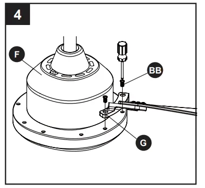
Hardware Used

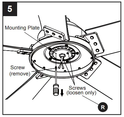
- Remove one of the mounting screws (R) on mounting plate of motor housing (F), then loosen the other two.
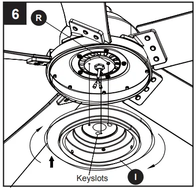
- Insert the wires from the motor housing (F) through the center hole in the switch housing (I). Attach the switch housing (I) to the mounting plate on motor housing (F) by placing the keyslot holes from the switch housing (I) onto the two protruding mounting screw (R) heads.
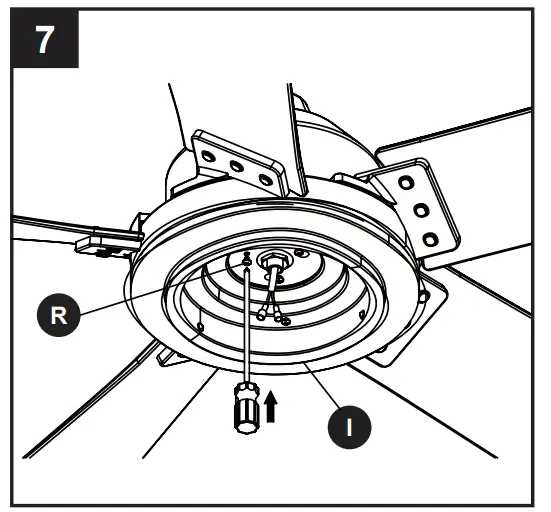
- Adjust the switch housing (I) until the screw heads are aligned with the keyholes, then re-insert mounting screw (R) previously removed on step 5. Tighten all mounting screws (R) securely.
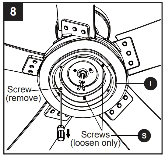
- Remove one of the screws (S) on switch housing (I), then loosen the other two
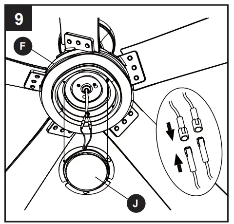
- Connect the 2 single pin connectors from the light kit (J) to the 2 single pin connectors from motor assembly(F). Connect the black wire to black wire, and white wire to white wire.
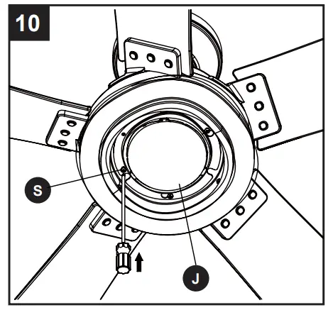
- Adjust the light kit (J ) until the screw heads are aligned with the keyholes, then re-insert mounting screw (S) previously removed on step 8. Tighten all mounting screws (S) securely.
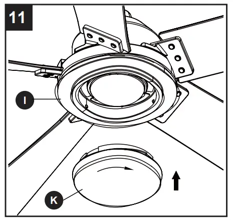
- Secure the bowl (K) to switch housing (I) by twisting in a clockwise direction. Do not over-tighten.
OPERATING INSTRUCTIONS
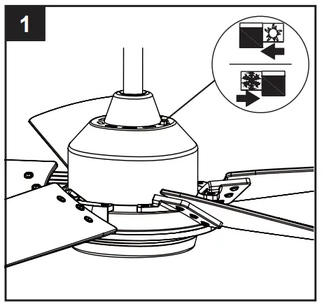
- When the season changes, you may want to change the direction in which the fan spins.
In warmer weather, counterclockwise rotation creates a downward airflow, which cools the air. Push the switch LEFT and see a SUN icon.
In cooler weather, clockwise rotation creates an upward airflow,which moves hot air from the ceiling. Push the switch RIGHT and see a SNOWFLAKE icon.
WARNING: Turn off and wait for fan to stop before flipping the reverse switch.
Note: Use a small screwdriver or ballpoint pen to move the reverse switch if you have difficulty doing so by hand.
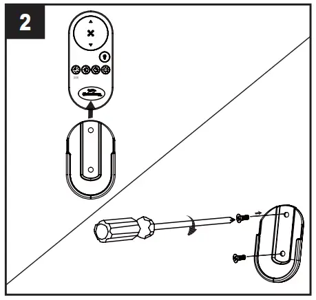
- Slide the transmitter out of the transmitter holder. Select a location to install your transmitter holder. Attach the transmitter holder with screws provided.
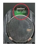
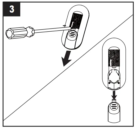
- Be sure to use a tool to depress the hook to remove the battery cover, don’t forcibly open.
- To make fan operational, install a 3V CR2032 battery (included). Replace the battery cover.
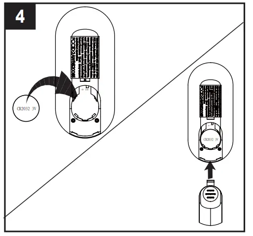
NOTE: If not used for long periods of time, remove battery to prevent damage to transmitter. Store the remote away from excessive heat and humidity.
NOTE: Each transmitter of this remote control carries a unique ID code to facilitate communication between paired devices. The ID code is set by factory and is not user changeable. However, you will be required to perform an ‘ID code learning ° process manually under these circumstances:
If you have multiple fans installed within a close proximity and want to control all fans using a same remote transmitter.
NOTE: Each fan requires its own receiver. When your remote control is not responding(make sure battery is not flat)
When your remote control is not responding(make sure battery is not flat)
After you have replaced a faulty transmitter or receiver with a new one.
Otherwise the remote control will not work. To perform this process manually, follow steps below:
After installing and wiring the unit, restore power to your fan, press and hold the transmitter “ ” button for 5 seconds until the fan beeps to indicate the code learning process have been completed. This operation must be completed within 1 minute after restore power to the fan
 - The buttons on the remote control the fan speed and light as follows:
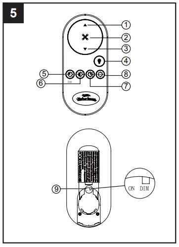
NOTE: Factory set is on “DIM” position. If the light is not dimmable, slide it to “ON” position, otherwise it may cause the light to flicker.
NOTE: This receiver has a preset memory function; when the switch is turned OFF, the control will remember the light intensity and fan speed. When the switch is turned ON, the light and fan will resume operation as they were prior to the switch being turned OFF.
CARE AND MAINTENANCE
Important: Shut off main power supply before beginning any maintenance. Do not use water or a damp cloth to clean the ceiling fan.
- At least twice each year, tighten all screws and lower canopy to check mounting plate screws.
- Clean fan housing with only a soft brush or lint-free cloth to avoid scratching the finish. Clean blades with a lint-free cloth. You may occasionally apply a light coat of furniture polish to wood blades for added protection.
TROUBLESHOOTING
| PROBLEM | PROBABLE CAUSE | CORRECTIVE ACTION |
| Fan sounds noisy |
|
|
| Fan wobbles |
|
|
| Fan does not start |
|
|
| Light does not work | Wrong wire connection. | Refer to Step 9, page 12 to ensure all wire connections were done correctly. |
LIMITED LIFETIME WARRANTY
The manufacturer warrants this fan to be free from defects in workmanship and material present at time of shipment from the factory for life (with limitations) from the date of purchase. This warranty applies only to the original purchaser. The manufacturer agrees to correct such defect at no charge or, at our option, replace the ceiling fan with a comparable or superior model.
To obtain warranty service, present a copy of your sales receipt as proof of purchase. All cost of removal and reinstallation are the expressed responsibility of the purchaser. Any damage to the ceiling fan by accident, misuse or improper installation, or by affixing accessories not produced by this warranty, are at the purchaser’s own responsibility. The manufacturer assumes no responsibility whatsoever for fan installation during the limited lifetime warranty. Any service performed by an unauthorized person will render the warranty invalid.
Due to varying climatic conditions, this warranty does not cover changes in brass finish, rusting, pitting, tarnishing, corroding or peeling. Brass finish fans maintain their beauty when protected from varying weather conditions.
Any replacement of defective parts for the ceiling fan must be reported within the first year from the date of purchase. For the balance of the warranty, call our customer service department at 1-800-643-0067 for return authorization and shipping instructions so that we may repair or replace the ceiling fan. Any fan or parts returned improperly packaged is the sole responsibility of the purchaser. There is no further expressed warranty. The manufacturer disclaims any and all implied warranties.
The duration of any implied warranty which can not be disclaimed is limited to the lifetime limited period as specified in our warranty. The manufacturer shall not be liable for incidental, consequential or special damages arising at or in connection with product use or performance except as may other wise be accorded by law. This warranty gives you specific legal rights, and you also have other rights which vary from state to state. This warranty supersedes all prior warranties.
NOTE: A small amount of “ wobble ” is normal and should not be considered a defect.
FCC WARNING
This device (including remote control and LED module) complies with Part 15 of the FCC Rules. Operation is subject to the following two conditions:
- This device may not cause harmful interference, and
- this device must accept any interference received, including interference that may cause undesired operation. Please note that changes or modifications not expressly approved by the party responsible for compliance could void the user’s authority to operate the equipment.
Note: Both the remote control and LED module have been tested and found to comply with the limits for Class B digital device,pursuant to part 15 of the FCC Rules. These limits are designed to provide reasonable protection against harmful interference in a residential installation. The remote control generates, uses and can radiate radio frequency energy and, if not installed and used in accordance with the instructions, may cause harmful interference to radio or television reception, which can be determined by turning the equipment off and on, the user is encouraged to try to correct the interference by one or more of the following measures:
- Reorient or relocate the receiving antenna.
- Increase the separation between the equipment and the receiver.
- Connect the equipment into an outlet on a circuit different from that to which the receiver is connected.
- Consult the dealer or an experienced radio/TV technician for help.
REPLACEMENT PART LIST
For replacement parts, call our customer service department at 1-800-643-0067, 8 a.m. – 8 p.m., EST, Monday – Sunday.
| Part | Description | Part# |
| A | Mounting Bracket | A102-0219239 |
| B | Downrod Assembly | A103-0328499 |
| C | Canopy | A101-0150499 |
| D | Canopy Cover | A108-0013499 |
| E | Coupling Cover | A106-0130499 |
| G | Blade Arm | A143-0386499 |
| H | Blade | A141-0640030 |
| I | Switch Housing | A121-0467499 |
| J | Light Kit | A187-0515036 |
| K | Bowl | A182-0500036 |
| L | Remote Unit | A137-0540031 |
| AA | Blade Screw | B168-0640005 |
| BB | Blade Arm Screw |
Customer Service
Questions, problems, missing parts?
Before returning to your retailer, call our customer service department at 1-800-643-0067, 8 a.m. – 8 p.m., EST, Monday – Sunday