Owner’s Manual & Safety Instructions
Save This Manual Keep this manual for the safety warnings and precautions, assembly, operating, inspection, maintenance, and cleaning procedures. Write the product’s serial number in the back of the manual near the assembly diagram (or month and year of purchase if the product has no number). Keep this manual and the receipt in a safe and dry place for future reference.
![]()
Greenhouse
8’5″ L x 6’3″ W x 6’5″ H

47712
Visit our website at: http://www.harborfreight.com
Email our technical support at: [email protected]
When unpacking, make sure that the product is intact and undamaged. If any parts are missing or broken, please call 1-888-866-5797 as soon as possible.
 Read this material before using this product. Failure to do so can result in serious injury. SAVE THIS MANUAL.
| WARNING SYMBOLS AND DEFINITIONS | |
| This is the safety alert symbol. It is used to alert you to potential personal injury hazards. Obey all safety messages that follow this symbol to avoid possible injury or death. | |
 |
Indicates a hazardous situation that, if not avoided, will result in death or serious injury. |
|
Indicates a hazardous situation that, if not avoided, could result in death or serious injury. |
 |
Indicates a hazardous situation that, if not avoided, could result in minor or moderate injury. |
 |
Addresses practices not related to personal injury. |
IMPORTANT SAFETY INFORMATION
The warnings, precautions, and instructions discussed in this manual cannot cover all possible conditions and situations that may occur. The operator must understand that common sense and caution are factors, which cannot be built into this product but must be supplied by the operator.
Assembly / Installation Precautions
- Assemble only according to these instructions. Improper assembly can create hazards.
- Wear ANSI-approved safety goggles and heavy-duty work gloves during assembly.
- This unit contains pieces with sharp edges. The machined edges of the aluminum parts and the ends of the panel clips may be sharp. Handle all parts carefully.
- Keep assembly area clean and well-lit.
- Keep bystanders out of the area during assembly.
- Do not assemble when tired or when under the influence of alcohol, drugs, or medication.
- Product capabilities apply to properly and completely assembled products only.
- Locate the Greenhouse on a flat, level, surface. A concrete foundation is recommended for a high-quality installation.
Use / Service Precautions
- This product is not a toy. Do not allow children to play in or climb on this product. Although this greenhouse does include some caps, there are still some exposed sharp edges. In addition, protective covers may fall off in time. Children must be supervised if allowed near the greenhouse.
- SNOW/DEBRIS ACCUMULATION HAZARD. The heavy weight of accumulated snow or other debris can cause parts of this greenhouse to buckle suddenly. Do not allow debris to accumulate on top of the greenhouse. If snowfall is expected, place additional supports (not provided) underneath the Crown (35). NEVER enter a greenhouse with accumulated debris on top.
- Use as intended only.
- Inspect periodically; replace damaged parts immediately and do not enter the greenhouse if parts are loose or damaged.
- For your safety, service and maintenance should be performed regularly by a qualified technician.
![]() SAVE THESE INSTRUCTIONS.
SAVE THESE INSTRUCTIONS.
Specifications
| Overall Dimensions | 98-1/2″ L x 75-7/8″ W x 77″ H |
| Window Dimensions | 23″ L x 20″ W |
| Door Dimensions | 64″ H x 24″ W x 1-1/4″ Thick |
| Materials | Aluminum Frame Transparent Polycarbonate Sheets |
| Aluminum Thickness | 0.038″ |
| Polycarbonate Sheet Thickness | 0.165″ |
Foundation Installation
![]() Read the ENTIRE IMPORTANT SAFETY INFORMATION section at the beginning of this document including all text under subheadings therein before set up or use of this product.
Read the ENTIRE IMPORTANT SAFETY INFORMATION section at the beginning of this document including all text under subheadings therein before set up or use of this product.
IMPORTANT–READ THE FOLLOWING CAREFULLY BEFORE PROCEEDING
- Prior to assembly, a proper foundation must be laid. The greenhouse must be properly supported to help prevent property damage and injury in the event of strong winds or inclement weather. Wind and ground conditions may vary from site to site and may affect the practicality and effectiveness of anchoring methods substantially. If you have any
doubt regarding the stability of the foundation you are to use, consult a professional. - It is always your responsibility to ensure that the greenhouse is properly anchored. Harbor Freight Tools cannot be held responsible for personal injury, damage to the greenhouse, or other property damage that occurs as a result of improperly anchoring the greenhouse.
- Be certain to check with local authorities to obtain all required building permits and to familiarize yourself with any building codes that may apply.
- Decide on a location for the greenhouse. The location should optimally be a level, well-lit area that is sheltered from the wind. The door of the greenhouse should not open towards the prevailing wind, if possible.
Concrete Anchor Foundation
- This foundation will be assembled out of 4 x 4 treated lumber, hardware, and prefabricated concrete anchors (none provided).
- Assemble the 4 x 4 pieces in the dimensions shown in the diagram below. The wood will need to be trimmed to fit. Make certain that the assembly is square and level.
The diagonal dimensions, from outside corner to outside corner, should be 123 3/4″ each. - Securely assemble the frame together using proper hardware.
- Dig a hole for each of the concrete anchors in the positions shown. The hole should be slightly oversized and should be deep enough so that the frame will rest almost on the ground when installed.
- Carefully place the anchors in the holes, and place the frame on the anchors. Use a level on the frame to make sure that the anchors are sunk to the proper depth.
If any anchors need to be raised, partially fill the hole under the anchor with sand or gravel. - Once the frame is level, secure it to the anchors. Fill up the holes the rest of the way with the earth you removed previously.
- Optional: For convenience, you may fill the frame at this point with a proper fill material, such as gravel (not included).
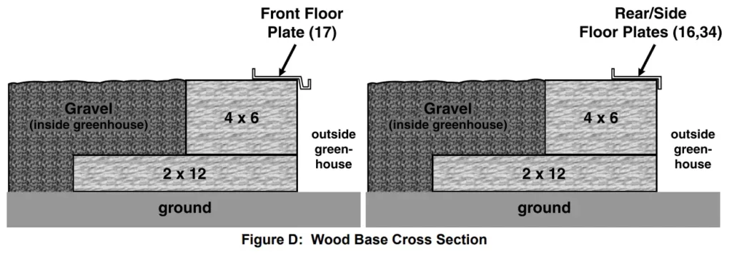
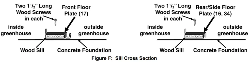
- There are four Floor Plates to position on the foundation; the Front Floor Plate (17), the Rear Floor Plate (16), and two Side Floor Plates (34). (See Figure G on page 8.)
- Match the length of each of the four Floor Plates (16, 17, 34) with the appropriate length of each edge of the base. Place the Front Floor Plate (17) on the side that the door will face.
NOTE: Position the four Floor Plates (16, 17, 34) with their outer edges overhanging the outer edges of the frame, as shown below. Do not secure the Floor Plates to the Frame at this time.
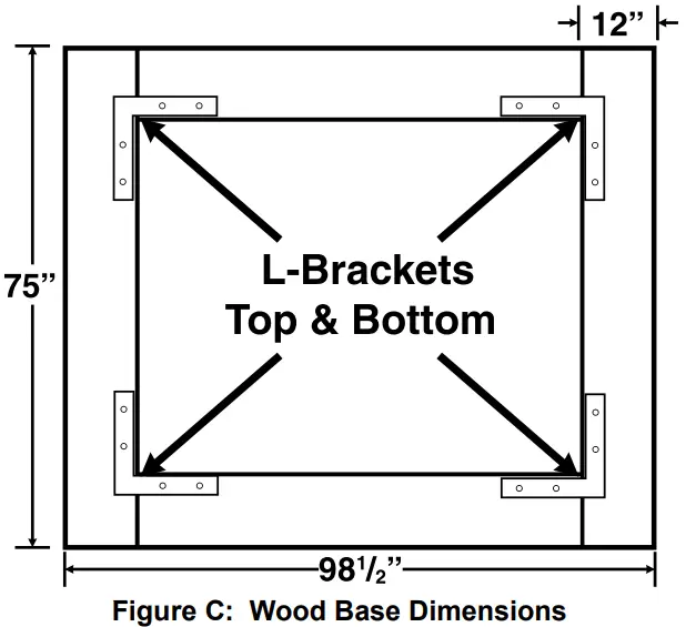
Treated Wood Base Foundation
- The wood base will be assembled out of 4 x 6 and 2 x 12 treated lumber, hardware (including galvanized lag bolts/deck screws), and fill material, such as gravel (none provided).
- Assemble the 2 x 12 pieces in the dimensions shown in the diagram below. The wood will need to be trimmed to fit. Make certain that the assembly is square and level. The diagonal dimensions, from outside corner to outside corner, should be 123 3 /4″ each. Also, use a level to ensure that the base is even. If needed, fill under sections of the base to make sure it is level.
- Assemble the 4 x 6 pieces on top of the base you just assembled, as shown in the cross-section below. Fill the base with the fill material up to the top of the 4 x 6’s.
- There are four Floor Plates to position on the foundation; the Front Floor Plate (17), the Rear Floor Plate (16), and two Side Floor Plates (34). (See Figure G on page 8.)
- Match the length of each of the four Floor Plates (16, 17, 34) with the appropriate length of each edge of the base. Place the Front Floor Plate (17) on the side that the door will face.
NOTE: Position the four Floor Plates (16, 17, 34) with their outer edges overhanging the outer edges of the base, as shown below. Do not secure the Floor Plates to the Base at this time.
Concrete Slab Foundation
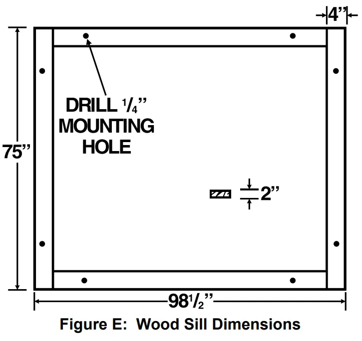
Constructing a Wooden Sill
- The greenhouse must be attached to a wood sill, and not directly to a concrete slab. Use four 4″ wide by 2″ thick wooden boards (not provided) to construct a sill.
- Cut the four boards to the proper dimensions shown.
- Place the four boards to form a rectangle on a level floor surface.
- Exact dimensions may vary slightly. Lay the base components out together, square them, then take actual measurements. Both diagonal measurements, from outer corner
to outer corner, should be 123 3/4″ each. - Secure the boards together at the corners using wood screws (not provided).
Attaching the Sill to the Concrete Slab
- A concrete slab foundation upon which The greenhouse will be positioned will help to ensure stability. The slab can be slightly oversize.
- Drill two ¼″ holes through each of the four boards.
- Next, use the two predrilled holes in each board as a template to mark the points where eight anchor holes will be drilled in the concrete floor. Then, temporarily remove the sill.
- Where previously marked on the concrete floor, drill all eight¼″ diameter, minimum ¼″ deep, anchor holes. Blow the concrete dust out from the drilled holes.
- Move the four boards back to the concrete floor surface, and align all eight predrilled holes in the four boards with the eight previously drilled anchor holes. If necessary, level the boards by inserting stainless steel shims (sold separately) between the boards and the concrete floor. Do not exceed ½″ shim thickness.
- Secure the four boards to the concrete floor, using eight ¼″ diameter anchor bolts of appropriate length, eight washers, and eight nuts (not provided).
Positioning the Floor Plates on the Sill
- There are four Floor Plates to attach to the sill; the Front Floor Plate (17), the Rear Floor Plate (16), and two Side Floor Plates (34). (See Figure G on page 8.)
- Match the length of each of the four Floor Plates (16, 17, 34) with the appropriate length of each of the four foundation boards. Place the Front Floor Plate (17) on the side that the door will face.
NOTE: Position the four Floor Plates (16, 17, 34) with their outer edges overhanging the outer edges of the sill, as shown below. Do not secure the Floor Plates to the Sill at this time.
Frame Assembly
![]() Read the ENTIRE IMPORTANT SAFETY INFORMATION section at the beginning of this document including all text under subheadings therein before set up or use of this product.
Read the ENTIRE IMPORTANT SAFETY INFORMATION section at the beginning of this document including all text under subheadings therein before set up or use of this product.
- Unless noted otherwise, attach all frame parts using the Bolts (43) and Nuts (52) provided. Tighten nuts only about ¼ ” turn past finger tight; be careful not to overtighten.
- Layout all parts by number prior to assembly.
- Use an assistant or appropriate support (not included) to keep the partially assembled parts upright during assembly. Use two assistants to assemble the Crown pieces to the rest of the frame.
- Assemble on a clear, calm day. Wind will damage the Greenhouse and make assembly difficult.
Assembling the Frame Edges
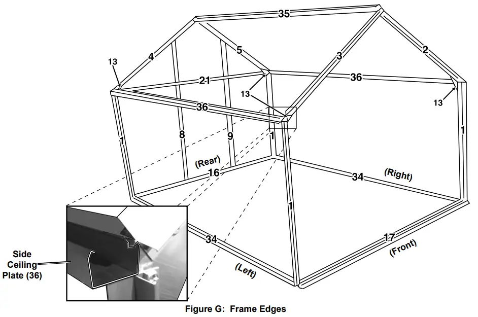
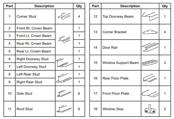
- There are four Corner Studs (1) to be attached to the four Floor Plates (16, 17, 34). Attach one Corner Stud (1) on the outside of each corner. Attach an End Cap (47) to the top outer corner of each Corner Stud (1).
- Once the four Corner Studs (1) are connected to the Floor Plates (16, 17, 34), drill three pilot holes 1 ½″ through each Floor Plate and into the underlying wood sill or base. Make sure not to drill into any of the hardware used earlier. Then, secure the Floor Plates to the foundation, using three 1 ½″ long wood screws (sold separately) for each Floor Plate.
- Attach a Side Ceiling Plate (36) flat against the inside of two Corner Studs (1). Make sure that the gutter on the Side Ceiling Plate is oriented correctly, see Figure G inset. At this point, the completed section of the frame will likely need support.
- Attach the Rear Ceiling Plate (21) to the inside of the two Corner Studs (1) that are over the Rear Floor Plate (16). Point the Rear Ceiling Plate’s flange inward. (See Figure G.)
- Attach the Left and Right Rear Studs (8,9) to the outside of the Rear Floor Plate (16) and Rear Ceiling Plate (21). Orient them so that the ends slope upwards toward the middle of the greenhouse. (See Figure G.)
Note: The heads of the Bolts (43) fit into the slot on the back of the Stud, holding the Bolts in place during assembly.
- Attach the remaining Side Ceiling Plate (36) along the other side, flat against the inside of the Corner Studs (1), with the gutter oriented properly.
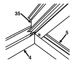
- At the side of the Greenhouse: Attach the Rear Right and Rear Left Crown Beams (4,5) to the outside of the Crown (35) with the angled edges towards the top. See diagram below, viewed from under the Crown, facing back.
- Attach the Front Crown Beams (2,3) to the Crown (35) in the same fashion as the Rear Crown Beams.
- Attach an End Cap (47) onto the outer end of each Crown Beam (2-5). Cover the gaps between the Crown Beams (between 2-3 & 4-5) with a Peak Cap (54) in each.
- Attach a Corner Bracket (13) at the top of each Corner Stud (1) so that the bracket faces upwards, see diagram below. At the Studs that the Rear Ceiling Plate (21) is connected to, the Bolt (43) holding the Ceiling Plate will need to be removed temporarily while the Bracket is installed between the Rear Ceiling Plate and the Corner Stud.
- With two assistants, lift the Crown Assembly and place the Crown Beams (2-5) on top of the Corner Brackets (13).
- Attach the remaining Side Ceiling Plate (36) flat against the inside of two Corner Studs (1). Once again, verify that the gutter on the Side Ceiling Plate is oriented correctly, see Figure C inset. At this point, the unit should be more stable.
- Place the Gutter Caps (48) onto the ends of the Side Ceiling Plates (36) oriented with a gap in the bottom to allow water to drain out of the gutters.
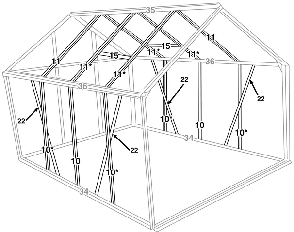
Assembling the Side and Roof Frames
IMPORTANT: Assemble all parts marked with an asterisk (*) above with an extra Bolt (43) in the slot.
Figure H: Stud and Brace Locations
- Attach three Side Vertical Studs (10) to a Side Floor Plate (34) and a Side Ceiling Plate (36). Make sure that they are assembled vertically, there are extra holes for the diagonals. Also, include extra Bolts in the Studs noted above with asterisks. Repeat this step for the remaining Side Floor Plate and Side Ceiling Plate. (See Figure H.)
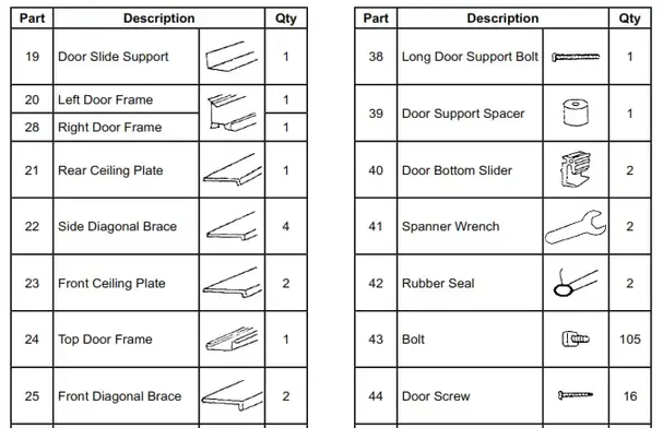
- Attach two Side Diagonal Braces (22) to a Side Floor Plate (34) and a Side Ceiling Plate (36) with the flange facing inward. Use the extra Bolt (43), noted in the caption above, to secure the center portion of each Diagonal Brace (22). Repeat this step for the remaining Side Floor Plate and Side Ceiling Plate. (See Figure H.)
- Attach the six Roof Studs (11) between the Crown (35) and the two Side Ceiling Plates (36). Include extra Bolts in the four Studs noted with an asterisk above. (See Figure H.)
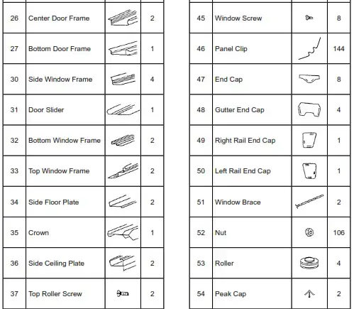
- Slide the Window Support Beams (15) onto the four Roof Studs (11) that you included extra bolts in, with the predrilled holes on the underside and the flat side facing the Crown (35). Use the extra Bolts (43), to secure the Beam loosely in place. It will need adjustment when installing the window.
- Using two Window Screws (45), attach each Window Stop (18) to the Window Support Beam (15) with its tab pointing towards the Crown (35). Both should be on the underside of their Window Support Beam, inside the greenhouse.
Assembling the Front Frame
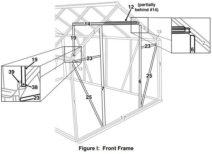
- Attach the Right and Left Doorway Studs (6,7) to the Front Right and Left Crown Beams (2,3) and the Front Floor Plate (17) as shown above. The cutoff corners on the Studs should be at the top and should face away from the center of the greenhouse. (See Figure I and right inset.)
- Attach the Front Diagonal Stud (25) to the lower Bolt on the Corner Bracket (13) and bottom of the Front Floor Plate (17). The flange should face inside. (See Figure I.)
- Attach the other Front Diagonal Stud (25) in the same way on the opposite side.
- Attach a Front Ceiling Plate (23) to the Bolt (43) on the Corner Bracket (13) that is right above the Diagonal-Bracket connection. Connect the other end to the Left Doorway Stud (7). Attach the remaining Front Ceiling Plate (23) between the Corner Bracket (13) and Right Doorway Stud (6). (See Figure I.)
- Attach the Top Doorway Beam (12) between the Front Right and Left Crown Beams (2,3). Turn it so that the nicked corners are facing up and the two remaining holes are facing the outside to allow the Door Rail (14) to be attached.
- Attach the Vertical Extender (19) to the Front Left Crown Beam (3) using the Long Door Support Bolt (38) and Nut (52), with the Door Support Spacer (39) between the Extender and the Stud. (See Figure I, left inset.)
- Place three Bolts (43) in the Slot at the back of the Door Rail (14). Attach the Rail to the Top Doorway Beam (12) and the free end of the Vertical Extender (19), with the rounded side up. (See Figure I.)
Assembling/Installing the Door
The door is assembled using the Door Screws (44). The Screws thread directly into the rounded portions of the parts in the center of the door.
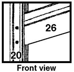
- Place the Left Door Frame (20) with the Rubber Seal (42) side down. Attach the Center Door Frames (26) to the Left Door Frame (20). Assemble them with the rounded portion facing the front, as shown to the right. These parts are also marked with an arrow that needs to point towards the top of the door.
- Attach the Right Door Frame (28) to the Center Door Frames (26) in the same way.
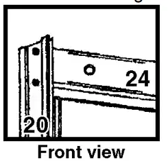
- Attach the Door Top Frame (24) to the Left and Right Door Frames (20 and 28). Turn them so that the rounded portion faces the front and that the flange where the pane will sit faces the center of the door, see the diagram to the right.
- Using two Bolts (43) and two Nuts (52), attach the Door Slider (31) to the Door Top Frame (24) with the rollers on the top of the door.
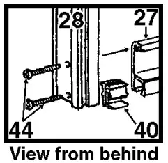
- Insert a Door Bottom Slider (40) into each end of the Bottom Door Frame (27). Install the Sliders correctly, with the gap facing the back of the door, see diagram to the right. Attach the Bottom Door The frame (27) to the Left and Right Door Frames (20,28) using two Screws (44) on each side – the top one into the Bottom Door Frame (27) and the bottom one into the Door Bottom Slider (40).
- Raise the assembled Door up and insert the first roller of its Door Slider (31) onto the Door Rail (14). Carefully align the first Bottom Door Slider (40) over the edge
of the Front Floor Plate (17), see illustration to the right. Carefully slide the door over and align the other top Roller and bottom Slider as was done earlier. - Once the door is installed, install a Bolt (43) and Nut (52) into the hole on each side of the Door Rail (14) to prevent the door from sliding off its rail. Attach the Right and Left Rail End Caps (49,50) onto the ends of the Door Rail.
Assembling/Installing the Windows
Follow the steps below for each of the two windows.
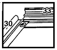
- Attach the Side Window Frames (30) to the Top Window Frame (33), as shown to the right.
- Insert Bolts (43) into the holes at the bottom of the Side Window Frames (30), so that the threads stick out the bottom of the window.
- Remove the protective film from both sides of the Window Pane (5A). Slide the Window Pane (5A) into the three-sided frame.
- Slide the Bottom Window Frame (32) onto the two bolts (43) and the Window Pane (5A). Secure it in place with Nuts (52). If needed, apply some pressure to the heads of the Bolts through the Window Pane to allow the Nuts to thread on properly.
- Attach the Window Brace (51) to the Bottom Window Frame (32) using two Window Screws (45). The holes on the Window Brace (51) should face away from the window.
- Slide the top edge of the Top Window Frame (33) into the slot at the top of the Crown (35), see illustration to the right. The window should
be aligned with the Window Brace (51) on the bottom. Slide the window into place over one Window Support Beam (15). Gradually lower it into place. - Loosen the nuts (52) holding the Window Support Beam (15) in place and slide the Window Support Beam (15) up to touch the window. Secure it into place.
Limited 90 Day Warranty
Harbor Freight Tools Co. makes every effort to assure that its products meet high quality and durability standards, and warrants to the original purchaser that this product is free from defects in materials and workmanship for the period of 90 days from the date of purchase. This warranty does not apply to damage due directly or indirectly, to misuse, abuse, negligence or accidents, repairs or alterations outside our facilities, criminal activity, improper installation, normal wear, and tear, or lack of maintenance. We shall in no event be liable for death, injuries to persons or property, or for incidental, contingent, special or consequential damages arising from the use of our product. Some states do not allow the exclusion or limitation of incidental or consequential damages, so the above limitation or exclusion may not apply to you. THIS WARRANTY IS EXPRESSLY IN LIEU OF ALL OTHER WARRANTIES, EXPRESS OR IMPLIED, INCLUDING THE WARRANTIES OF MERCHANTABILITY AND FITNESS.
To take advantage of this warranty, the product or part must be returned to us with transportation charges prepaid. Proof of purchase date and an explanation of the complaint must accompany the merchandise. If our inspection verifies the defect, we will either repair or replace the product at our election or we may elect to refund the purchase price if we cannot readily and quickly provide you with a replacement. We will return repaired products at our expense, but if we determine there is no defect, or that the defect resulted from causes not within the scope of our warranty, then you must bear the cost of returning the product. This warranty gives you specific legal rights and you may also have other rights which vary from state to state.
PLEASE READ THE FOLLOWING CAREFULLY
THE MANUFACTURER AND/OR DISTRIBUTOR HAS PROVIDED THE PARTS LISTS IN THIS DOCUMENT AS A REFERENCE TOOL ONLY. NEITHER THE MANUFACTURER NOR DISTRIBUTOR MAKES ANY REPRESENTATION OR WARRANTY OF ANY KIND TO THE BUYER THAT HE OR SHE IS QUALIFIED TO MAKE ANY REPAIRS TO THE PRODUCT, OR THAT HE OR SHE IS QUALIFIED TO REPLACE ANY PARTS OF THE PRODUCT. IN FACT, THE MANUFACTURER AND/OR DISTRIBUTOR EXPRESSLY STATES THAT ALL REPAIRS AND PARTS REPLACEMENTS SHOULD BE UNDERTAKEN BY CERTIFIED AND LICENSED TECHNICIANS, AND NOT BY THE BUYER. THE BUYER ASSUMES ALL RISK AND LIABILITY ARISING OUT OF HIS OR HER REPAIRS TO THE ORIGINAL PRODUCT OR REPLACEMENT PARTS THERETO OR ARISING OUT OF HIS OR HER INSTALLATION OF REPLACEMENT PARTS THERETO.
Parts Lists
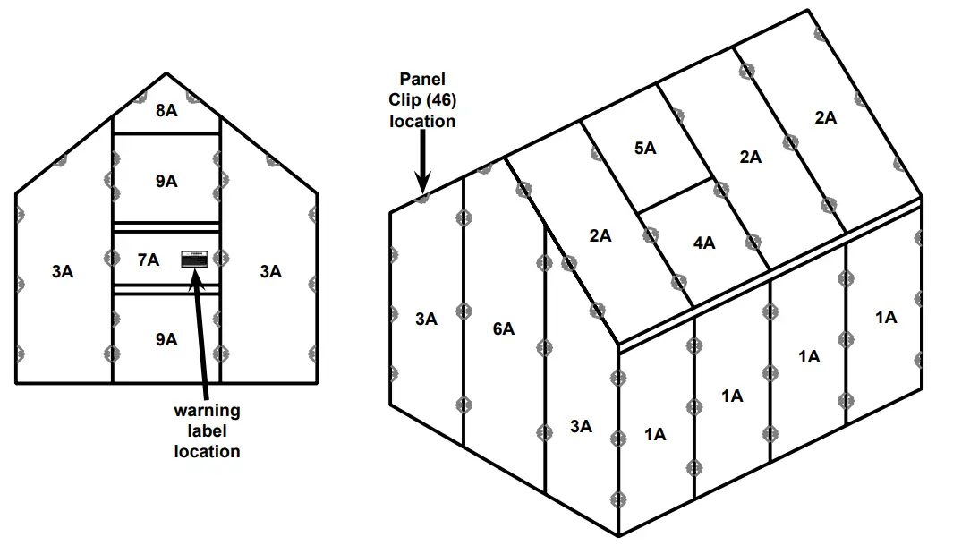

Parts List A- Panels
| Part | Description | Size | Qty |
| 1A | Side Panel | 23.81″ x 47.63″ | 8 |
| 2A | Roof Panel | 23.81″ x 44.48″ | 6 |
| 3A | Front/Rear Panel | 23.81″ x 65.35″ | 4 |
| 4A | Roof Window Pane | 23.81″ x 23.22″ | 2 |
| 5A | Window Pane | 23.62″ x 21.45″ | 2 |
| 6A | Rear Center Panel |
23.81″ x 73.70″ | 1 |
| 7A | Door Center Panel |
23.81″ x 9.44″ | 1 |
| 8A | Top Center Panel |
24.21″ x 9.13″ | 1 |
| 9A | Door Panel | 23.81″ x 23.70″ | 2 |

Record Serial Number Here:
Note: If a product has no serial number, record the month and year of purchase instead.
Note: Some parts are listed and shown for illustration purposes only, and are not available individually as replacement parts. Specify UPC 792363477123 when ordering parts.
![]()
26541 Agoura Road • Calabasas, CA 91302 • 1-888-866-5797
21d
For technical questions, please call 1-888-866-5797.
Item 47712