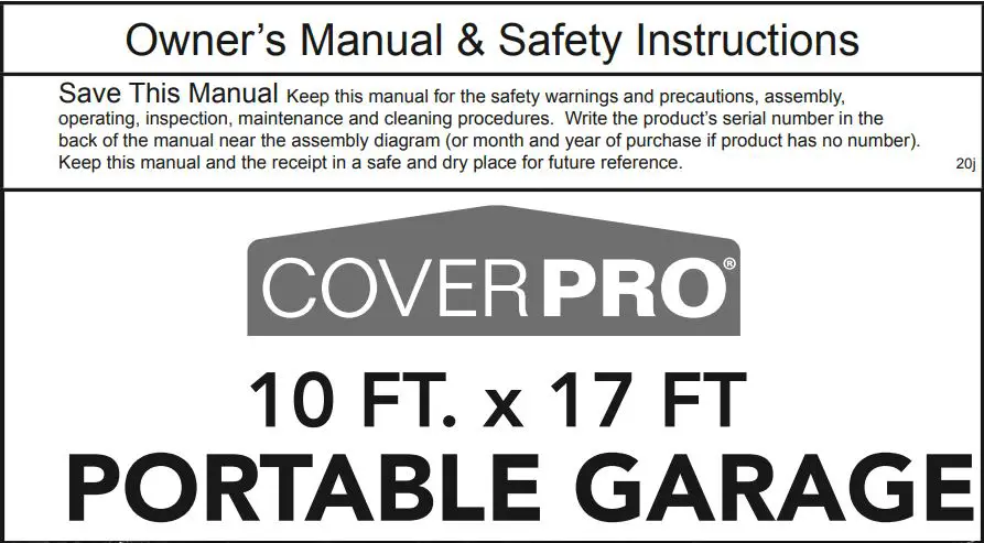
Harbor Freight COVER PRO 10FTx17FT Portable
Garage 62860 Owner's Manual
http://www.harborfreight.com
[email protected]
SAFETY
IMPORTANT SAFETY INFORMATION
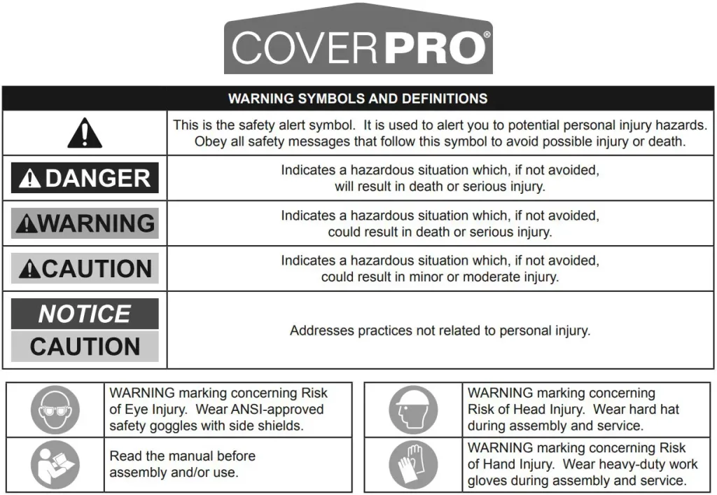
![]() WARNING
WARNING
Read all safety warnings and instructions. Failure to follow the warnings and instructions may result in serious injury. Save all warnings and instructions for future reference. The warnings, precautions, and instructions discussed in this instruction manual cannot cover all possible conditions and situations that may occur. It must be understood by the operator that common sense and caution are factors which cannot be built into this product, but must be supplied by the operator.
Assembly Precautions
- Do not assemble in windy conditions.
- Assemble and install only on flat, level, hard surface.
- Assemble and anchor only according to these instructions. Improper assembly or inadequate anchoring can create hazards.
- Check for utility lines, tree branches and other structures before assembling.
- Verify that installation surface has no hidden utility lines before anchoring.
- Wear ANSI-approved safety goggles, heavy-duty work gloves and hard hat during assembly and service.
- Keep assembly area clean and well lit.
- Keep bystanders out of the area during assembly.
- Do not assemble when tired or when under the influence of drugs or medication.
- Product capabilities apply to properly and completely assembled product only.
Use Precautions
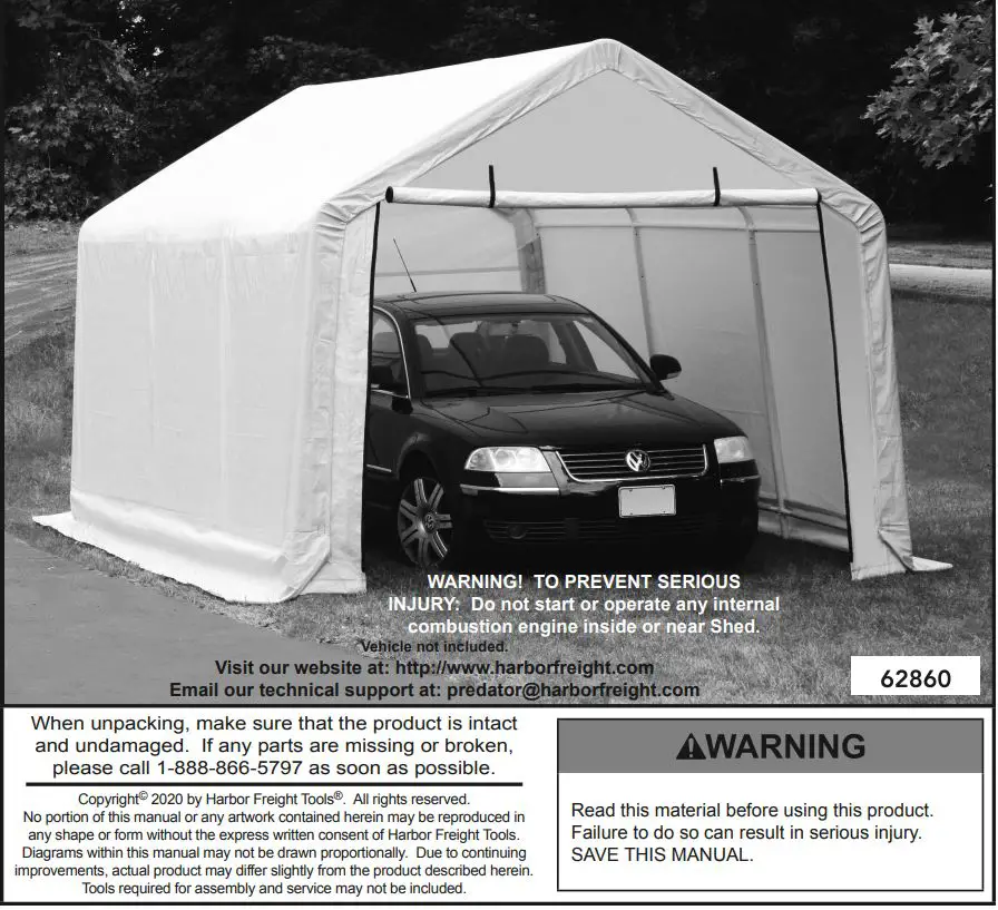
 CARBON MONOXIDE HAZARD Using an engine inside Shed CAN KILL YOU IN MINUTES. Engine exhaust contains carbon monoxide. This is a poison you cannot see or smell. NEVER use an engine inside Shed, EVEN IF cover is open. Only use an engine OUTSIDE and far away from Shed.
- DO NOT USE IN HIGH WIND. Remove cover if harsh weather or heavy rain threatens.
- For temporary use only. Do not use for long-term shelter.
- Do not use as tent. Does not meet tent flammability standards. Do not use grill, heater, or ignition sources inside or near cover.
- Do not allow snow, rainwater or debris to accumulate or pool on cover.
- Do not hang objects from any part of the Garage.
- This product is not a toy. Do not allow children to play with or near this item.
- Use as intended only.
- Inspect regularly, tighten all loose hardware and loose ropes, and secure all loosened anchors. If any parts are damaged, bent, or stretched, they must be replaced. Hardware may loosen during normal operation stresses. Loose hardware or damaged/altered parts will compromise the structural integrity of this product.
- Maintain product labels and nameplates. These carry important safety information. If unreadable or missing, contact Harbor Freight Tools for a replacement.
![]() SAVE THESE INSTRUCTIONS.
SAVE THESE INSTRUCTIONS.
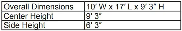
Specifications
Assembly
![]() Read the ENTIRE IMPORTANT SAFETY INFORMATION section at the beginning of this manual including all text under subheadings therein before set up or use of this product.
Read the ENTIRE IMPORTANT SAFETY INFORMATION section at the beginning of this manual including all text under subheadings therein before set up or use of this product.
Note: For additional information regarding the parts listed in the following pages, refer to Parts List and Diagram on page 14.
![]() WARNING
WARNING
TO PREVENT SERIOUS INJURY: Do not leave this product partially assembled. Assemble this product completely at one time.
At least 3 workers are required for assembly. Before starting assembly, review the instructions and make sure there is enough time and the proper tools available to properly assemble. Finger tighten all connections until assembly is done. Assemble on a flat, level surface.

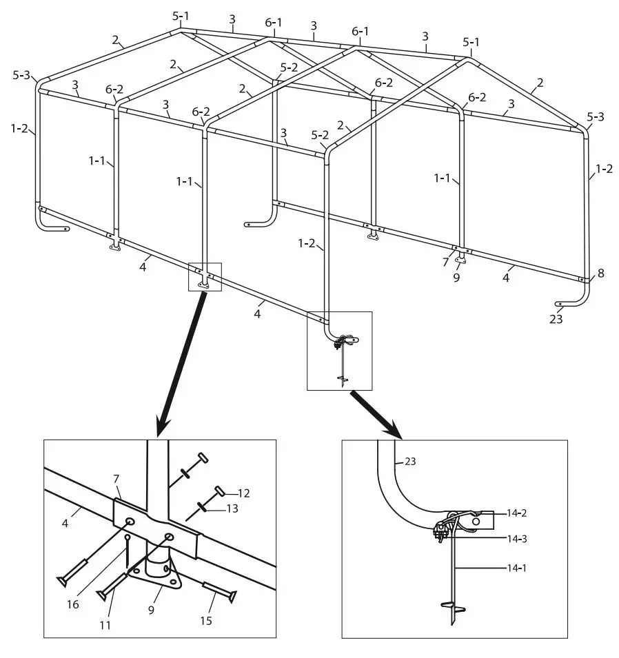
Frame Assembly Overview
Roof Frame Assembly
Much of this product’s assembly is done using slip fit construction. Make sure all parts seat completely and securely. A rubber mallet (sold separately) can be used to gently tap parts in place to ensure a tight fit.
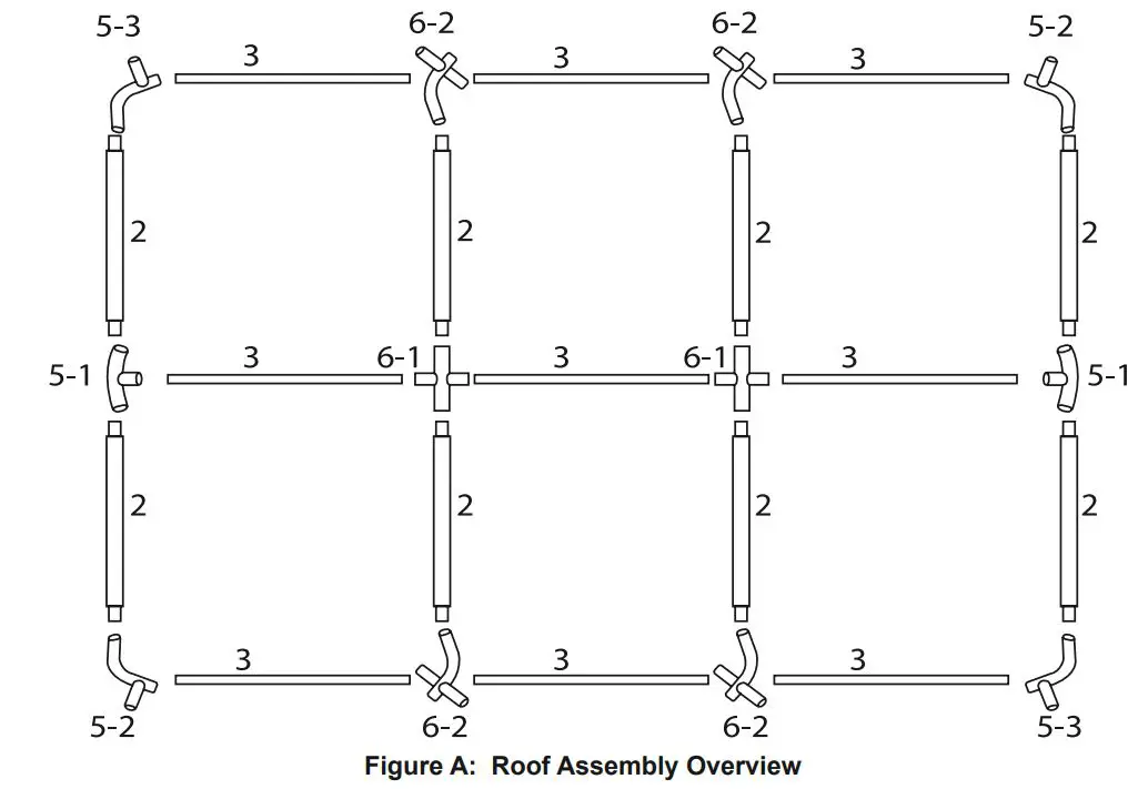
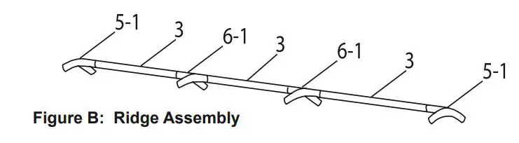
- Assemble ridge using three Rails (3) with 4-Way Ridge Connectors (6-1) between them, and a 3-Way Ridge Connector (5-1) on each end. The Rails connect to the straight ends of the Connectors and the curved, free ends of the Connectors are angled down, as shown.
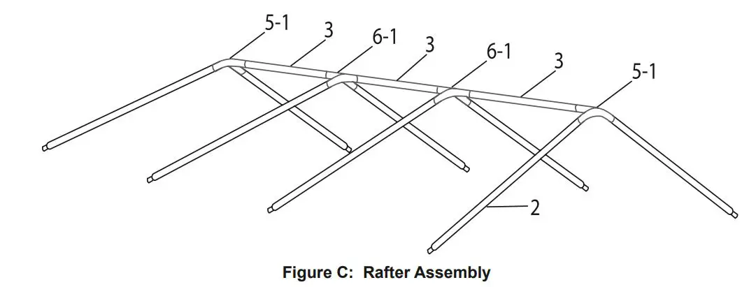
- Connect a Rafter (2) to each free end of every Connector (6-1, 5-1), as shown.
- Assemble a roof side rail using a 3-Way Side Connector B (5-3), then three Rails (3) with 4-Way Side Connectors (6-2) between them, and then a 3-Way Side Connector A (5-2) on the far end. The Rails connect to the straight ends of the Connectors, and the curved ends of all Connectors must face up angled the same direction, as shown. If that is not the case, incorrect connectors were used, or they were assembled backwards.
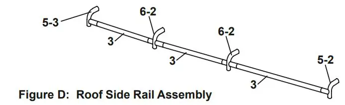
- Assemble a second identical roof side rail by repeating the instructions in step #3.
- Connect the roof side rail assemblies to the ends of the Rafters (2), as shown below.
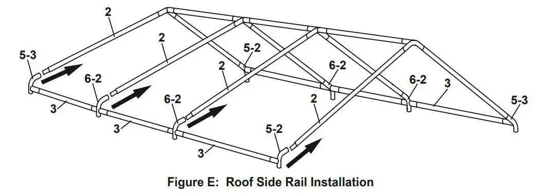
- Make sure all parts assembled up to this point are firmly joined together. Tap parts together gently with a rubber mallet (sold separately) if needed.
Stud, Foot, and Leg Assembly
- Assemble a Foot (9) to the bottom of each Center Stud (1-1):
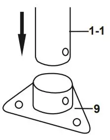
a. Place a Foot (9) onto the bottom of the Center Stud (1-1).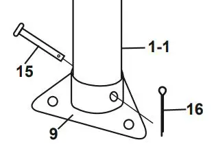
b. Align the holes and insert a Pin (15) through them.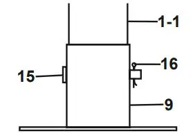
c. Insert a Cotter Pin (16) through the Pin, and spread end open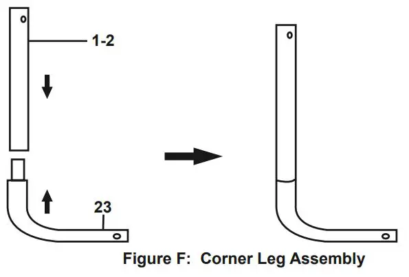
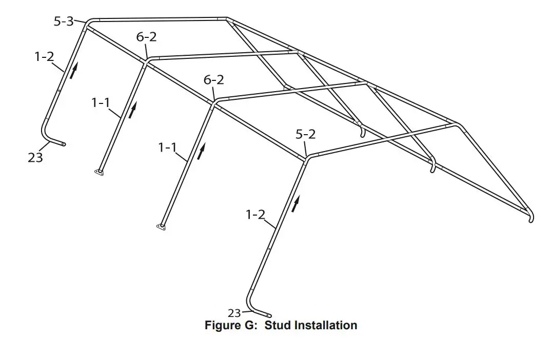
- Assemble a Corner Leg (23) to the bottom of each Corner Stud (1-2) as shown in Figure F.
Stud Installation - Have assistants raise one side of the roof assembly.
- Install the Center Studs (1-1) into the 4-Way Side Connectors (6-2), and the Corner Studs (1-2) into the 3-Way Side Connector A/B (5-2, 5-3) with the Corner Legs (23) facing inward.
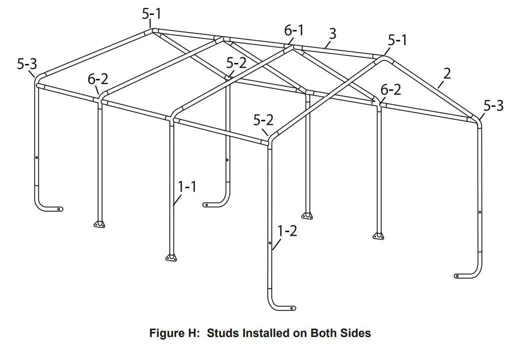
- After all four Studs (1-1, 1-2) are in place, rest that side of the assembly on the ground, and raise the other side.
- Install four Studs (1-1, 1-2) on the other side of the roof, as explained in step #2, above.
- Make sure all parts assembled up to this point are firmly joined together. Tap parts together gently with a rubber mallet (sold separately) if needed.
Anchoring Frame
![]() WARNING
WARNING
TO PREVENT SERIOUS INJURY: Contact local utility companies to ensure that the installation area is free of pipes, cables, and other hazards BEFORE installing anchors or choosing installation area.
- Position the frame in the desired installation location.
The location must be flat, level, and stable with good locations for the Anchors (14-1). - Level the frame end-to-end and side-to-side.
- Measure the width of the frame at front and back, it should be 10 2 wide. The distance diagonally in one direction should be equal to the distance diagonally in the other direction. If any measurements do not match, adjust the frame and retake measurements until they are equal within a reasonable tolerance.
Note: If measurements cannot be made correct, then parts may not be seated together properly.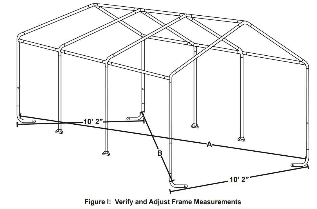
- Once the frame is positioned, levelled, and squared, anchor the four Corner Legs (23) as follows:
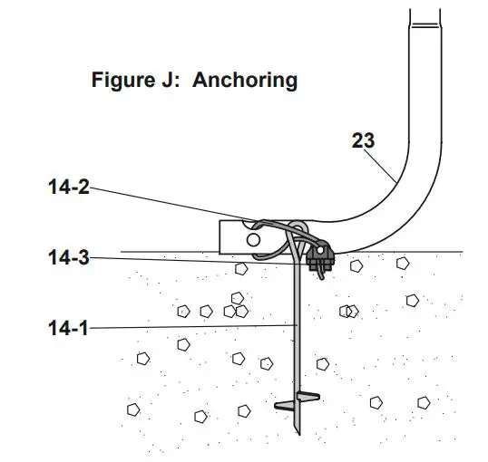
- a. Thread the Anchor (14-1) into the ground near the Corner Leg (23) until the top of the Anchor only extends about 3 above the ground.
Note: Verify that there are no utility lines nearby before driving anchors. If there are rocks or other obstacles, holes may need to be drilled first to allow proper anchoring. - b. Insert a Cable (14-2) through the anchor and through the Corner Leg (23), as shown.
- c. Pull the Cable (14-2) tight and secure it using a Cable Clamp (14-3). Tighten the two nuts on the Cable Clamp (14-3) evenly to secure the Cable (14-2).
- d. Repeat for all four Anchors (14-1) and Corner Legs (23).
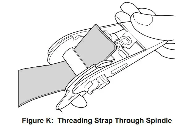
Securing Ratchet Tie-downs
Note: Use these instructions when installing Door, Back, and Roof cover.
- Thread the strap through the spindle of the Ratchet (22) as far as it will go.
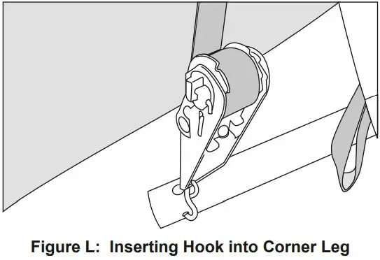
- Insert the S-hook of the Ratchet into the hole in the Corner Leg (23).
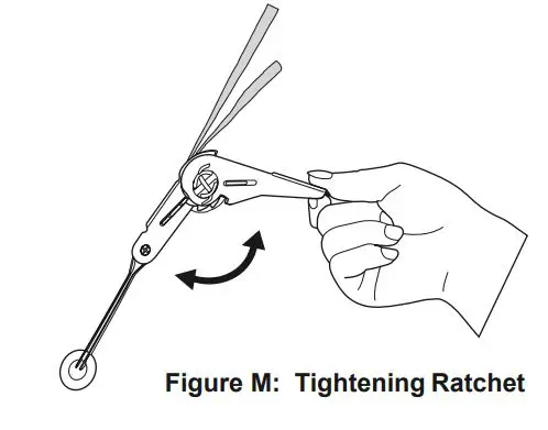
- Lift and lower the Ratchet’s handle to wind and tighten the strap onto the spindle.
Excessive tightening will damage straps, Covers, and Corner Legs.
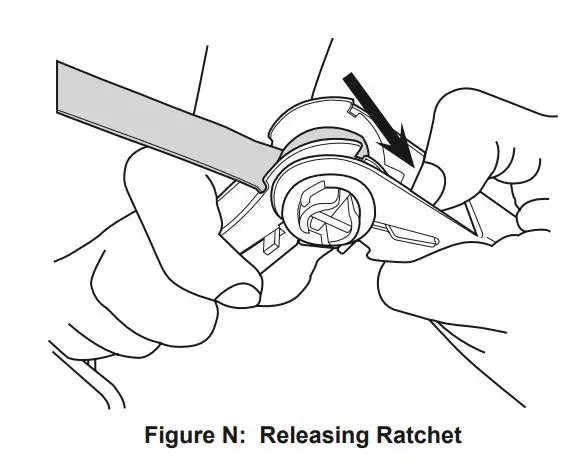
Releasing Ratchet Tie-downs
- Depress the spring-loaded bar on the handle.
- Open ratchet handle completely.
- Unwind the strap.
Door and Back Cover Installation
Note: When installing Door and Back cover, ensure that pre-installed straps are not pulled out of the Hem.
- Position the Door Cover (19) near where you want the front of the Portable Garage, and turn it so that the zipper faces the outside of the Portable Garage, and the warning tag faces inside.
- From the inside, disconnect the Rail (3) from the 3-Way Ridge Connector (5-1), and place the gap at the top center of the Door Cover around the Ridge Connector, as shown. Note that the Door Cover’s flaps wrap around the Rafters (2), and the strap is positioned inside the frame. DO NOT ATTEMPT TO INSERT ANY FRAMEWORK TUBING INTO THE HEM ON THE COVER FLAPS.
- Reconnect the Rail (3) securely to the 3-Way Ridge Connector (5-1).
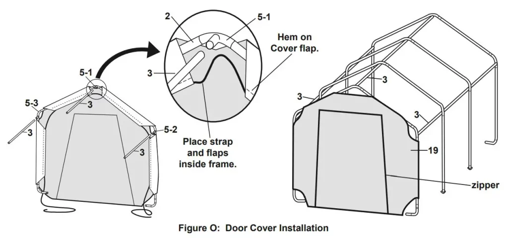
- Repeat step #2 for the 3-Way Side Connectors A/B (5-2, 5-3) so that the Door Cover (19) looks as shown in the illustrations above.
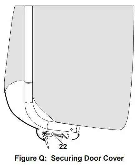
- Use Ratchet Tie-downs (22) to attach the Cover to the Corner Legs (23). Refer to Securing Ratchet Tie-downs on page 10 and Figure Q above.
- Repeat steps #1 4 above to install the Back Cover (20) to the other end of the Portable Garage.
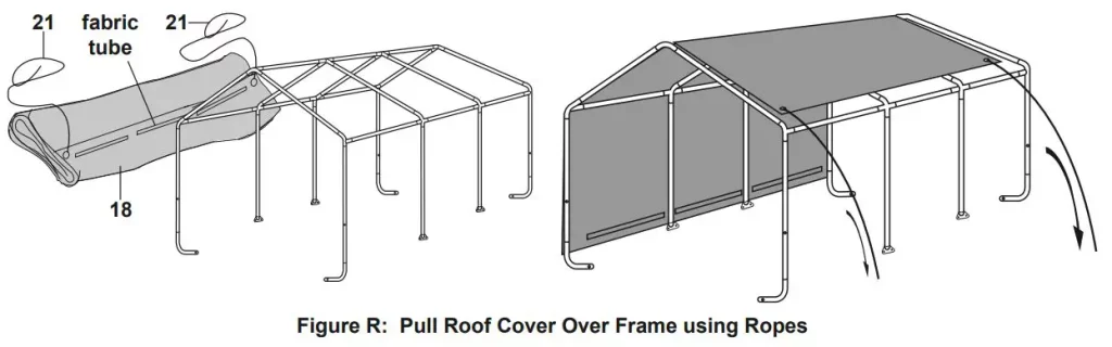
Roof Cover Installation
Note: Door and Back Covers (19, 20) not shown on illustrations to provide a clear view of installation.
- Lay the Roof Cover (18) on the ground next to the frame. Make sure that the edges with black straps are alongside the Door/Back Covers (19,20) and one set of the fabric tubes is facing upwards, see Figure R.
- Tie each Rope (21) through an eyelet at the corner of the Roof Cover.
- Throw the other ends of the Ropes (21) over the frame.
- Move to the other side of the frame and pull the Cover over the frame. Make sure that the Roof Cover is centred on the frame. If small adjustment is needed, two people should pull together from the same end of the Portable Garage so that the Roof Cover does not become twisted.
- Insert the Bottom Rails (4) into the fabric tubes on each side of the Roof Cover. Make sure the Bottom Rails are level and horizontal.
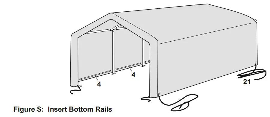
- Attach the Bottom Rails (4) to the Corner Studs (1-2) using 3-Way Rail Clamps (8), Bolts, Nuts and Washers (11, 12, 13), and to the Center Studs (1-1) with 4-Way Rail Clamps (7), as shown in Figure T.
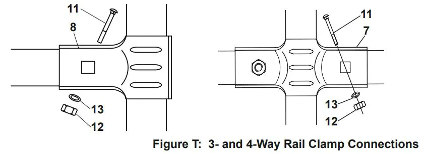
- Make sure that all the bottom cross rails are of the same height from the ground, then tighten all Nuts (12).
- Secure the four corners to the Corner Legs (23) using Ratchet Tie-downs (22); see Securing Ratchet Tie-downs on page 10.
Maintenance
![]() Procedures not specifically explained in this manual must be performed only by a qualified technician.
Procedures not specifically explained in this manual must be performed only by a qualified technician.
![]() WARNING
WARNING
TO PREVENT SERIOUS INJURY FROM PRODUCT FAILURE: Do not use damaged products. If damage is noted, have the problem corrected before further use.
Inspection
MONTHLY, inspect the general condition of the Portable Garage. Check for:
- loose ratchet tie downs, anchors, tube connections, and rail clamps (tighten as needed),
- torn or frayed covers, ropes, or cables,
- cracked, bent, or broken parts, and
- any other condition that may affect its safe operation.
Cleaning
- Immediately remove any accumulated debris from the cover with a broom, mop, or other soft-sided instrument from the outside. DO NOT use sharp instruments.
- PERIODICALLY, clean cover with mild soap and water. DO NOT use bleach or harsh abrasive products.
PLEASE READ THE FOLLOWING CAREFULLY
THE MANUFACTURER AND/OR DISTRIBUTOR HAS PROVIDED THE PARTS LIST AND ASSEMBLY DIAGRAM IN THIS MANUAL AS A REFERENCE TOOL ONLY. NEITHER THE MANUFACTURER OR DISTRIBUTOR MAKES ANY REPRESENTATION OR WARRANTY OF ANY KIND TO THE BUYER THAT HE OR SHE IS QUALIFIED TO MAKE ANY REPAIRS TO THE PRODUCT, OR THAT HE OR SHE IS QUALIFIED TO REPLACE ANY PARTS OF THE PRODUCT. IN FACT, THE MANUFACTURER AND/OR DISTRIBUTOR EXPRESSLY STATES THAT ALL REPAIRS AND PARTS REPLACEMENTS SHOULD BE UNDERTAKEN BY CERTIFIED AND LICENSED TECHNICIANS, AND NOT BY THE BUYER. THE BUYER ASSUMES ALL RISK AND LIABILITY ARISING OUT OF HIS OR HER REPAIRS TO THE ORIGINAL PRODUCT OR REPLACEMENT PARTS THERETO, OR ARISING OUT OF HIS OR HER INSTALLATION OF REPLACEMENT PARTS THERETO.
Record Product’s Serial Number Here:_________________
If product has no serial number, record month and year of purchase instead.
Some parts are listed and shown for illustration purposes only, and are not available individually as replacement parts.
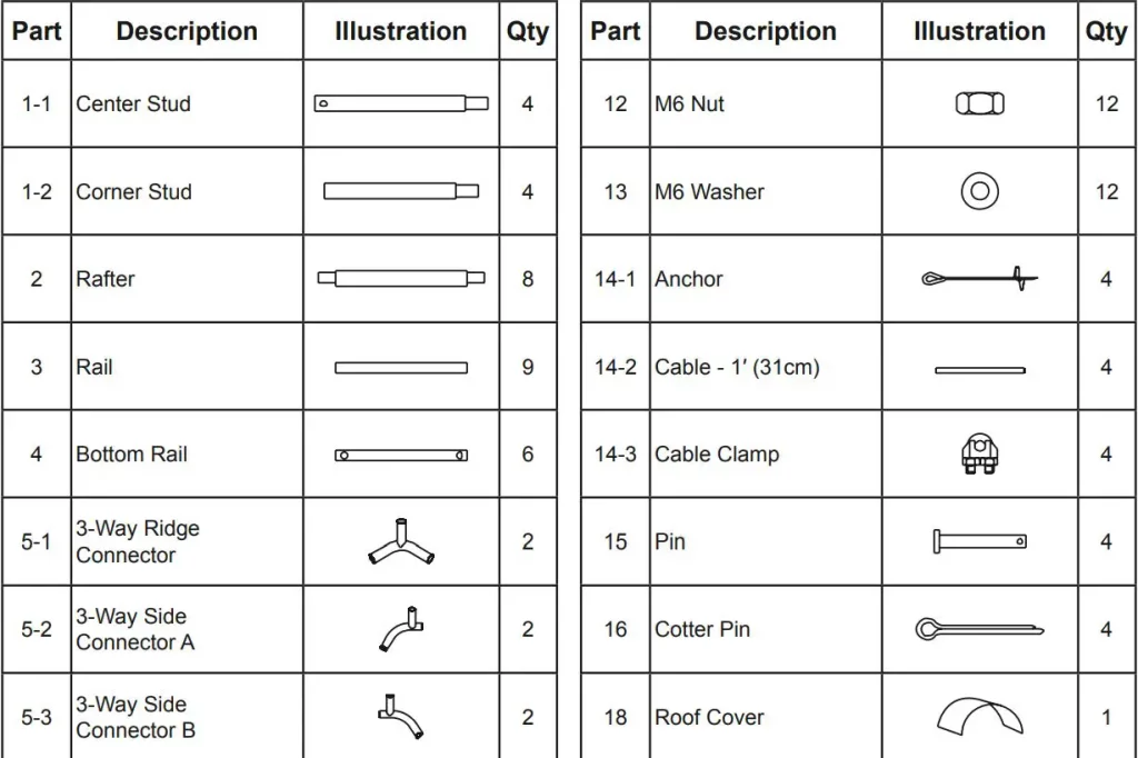
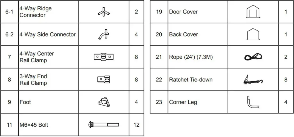
Parts List and Diagram
Parts List
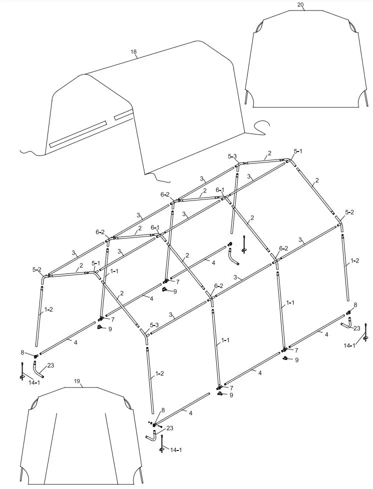
Assembly Diagram
Limited 90 Day Warranty
Harbor Freight Tools Co. makes every effort to assure that its products meet high quality and durability standards, and warrants to the original purchaser that this product is free from defects in materials and workmanship for the period of 90 days from the date of purchase. This warranty does not apply to damage due directly or indirectly, to misuse, abuse, negligence or accidents, repairs or alterations outside our facilities, criminal activity, improper installation, normal wear and tear, or to lack of maintenance. We shall in no event be liable for death, injuries to persons or property, or for incidental, contingent, special or consequential damages arising from the use of our product. Some states do not allow the exclusion or limitation of incidental or consequential damages, so the above limitation of exclusion may not apply to you. THIS WARRANTY IS EXPRESSLY IN LIEU OF ALL OTHER WARRANTIES, EXPRESS OR IMPLIED, INCLUDING THE WARRANTIES OF MERCHANTABILITY AND FITNESS.
To take advantage of this warranty, the product or part must be returned to us with transportation charges prepaid. Proof of purchase date and an explanation of the complaint must accompany the merchandise. If our inspection verifies the defect, we will either repair or replace the product at our election or we may elect to refund the purchase price if we cannot readily and quickly provide you with a replacement. We will return repaired products at our expense, but if we determine there is no defect, or that the defect resulted from causes not within the scope of our warranty, then you must bear the cost of returning the product. This warranty gives you specific legal rights and you may also have other rights which vary from state to state.
26541 Agoura Road · Calabasas, CA 91302 · 1-888-866-5797