Harbor Freight DAYTONA 3 Ton Super Duty Floor Jack DJ3000

IMPORTANT SAFETY INFORMATION
- Study, understand, and follow all instructions before operating this device.
- Do not exceed rated capacity.
- Use only on hard, level surfaces.
- Lifting device only. Immediately after lifting, support the vehicle with appropriate means.
- Do not move or dolly the vehicle while on the jack.
- Failure to heed these markings may result in personal injury and/or property damage.
- Lift only areas of the vehicle as specified by the vehicle manufacturer.
- No alterations shall be made to this product.
- Never work on, under or around a load supported only by this device.
- Do not adjust safety valve.
- Wear ANSI-approved safety goggles and heavy-duty work gloves during use.
- Keep clear of load while lifting and lowering.
- Lower load slowly
- Apply parking brake and chock tires before lifting vehicle.
- Lift vehicle only at manufacturer recommended locations.
- Inspect before every use; do not use if parts are loose or damaged, or if leaking hydraulic fluid
- Do not use for aircraft purposes.
- Do not use any objects (such as blocks of wood) in between Saddle Pad or Saddle and lifting point. Objects placed on the Saddle will reduce the stability of the Jack, and could allow the vehicle to slip off the Saddle and fall.
- The warnings, precautions, and instructions discussed in this manual cannot cover all possible conditions and situations that may occur. The operator must understand that common sense and caution are factors, which cannot be built into this product, but must be supplied by the operator
- The Handle socket may be held down by a clip under tension. Wear ANSI-approved safety goggles before freeing Handle socket. Remove clip carefully
- People with pacemakers should consult their physician(s) before use. Electromagnetic fields in close proximity to heart pacemaker could cause pacemaker interference or pacemaker failure.
 SAVE THESE INSTRUCTIONS.
IMPORTANT! Before first use:
Check hydraulic oil level and fill to 1/4″ below the Fill Plug hole as needed as stated on page 6. Thoroughly test the Jack for proper operation. If it does not work properly, bleed air from its hydraulic system as stated on page 6.
Specifications
| Weight Capacity | 3 Tons |
| Weight Capacity (lb.) | 6,000 |
| Maximum Height (in.) | 23.125 |
| Minimum Height (in.) | 3.75 |
| Handle Length (in.) | 50.25 |
| Front Wheel Diameter (in.) | 3.5 |
| Front Wheel Width (in.) | 2.0 |
| Rear Caster Diameter (in.) | 2.5 |
| Rear Caster Width (in.) | 1.375 |
| Saddle Pad Size (in.) | 5 x 5 sq. |
| Hydraulic Oil | non-detergent 22 weight |
| Weight (lb.) | 104 |
| Meets 2019 ANSI/ASME PASE standards | |
WARNING SYMBOLS AND DEFINITIONS |
|
|
This is the safety alert symbol. It is used to alert you to potential personal injury hazards. Obey all safety messages that follow this symbol to avoid possible injury or death. |
 |
Indicates a hazardous situation which, if not avoided, will result in death or serious injury |
 |
Indicates a hazardous situation which, if not avoided, could result in death or serious injury. |
 |
Indicates a hazardous situation which, if not avoided, could result in death or serious injury. |
 |
Addresses practices not related to personal injury. |
Features and Benefits
The Daytona [DJ3000] 3 Ton Professional Super Duty Jack was engineered for automotive professionals. The Model [DJ3000] features Advanced Rapid Pump® technology for fast lift times and exceptionally long life.
Long-Life Advanced Rapid Pump® Hydraulics
The hydraulic power unit is designed to provide over 5000 lift cycles with minimal wear.
An Integrated Magnetic Filtration (IMF) System prevents contaminants from damaging pump pistons and other high pressure components. Precision-engineered high performance seals along with a sealed non-vented reservoir ensure longer fluid life with no leaks.
Rapid Pump technology delivers twice the lift force with each stroke to lift heavy loads in half the time of conventional hydraulic systems. The pistons are continuously force-loaded to keep the pump handle in ready position during use. Load limiters with a bypass valve protect the pump if an overweight load is attempted.
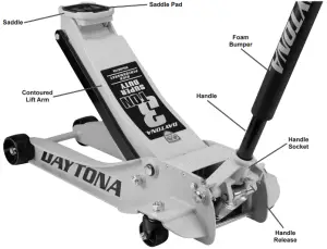
Low-Profile/High Lift Saddle
The Low Profile design gives you a minimum height of just 3.75 for working with low-clearance vehicles. The extended lift arm provides High Lift for a maximum height of 23.125 for plenty of working space when properly supported. The big 5 x 5 saddle supports lift points solidly without danger of slipping. The saddle can be removed to install lifting accessories (sold separately.)
Super Duty Strength and Durability
The Daytona Super Duty Professional Jack chassis is constructed from all-welded steel plate with I-beam reinforcement for extraordinary strength and reliability. Contoured steel wheels and casters roll smoothly with less surface area contact for exceptional mobility. Fully lubricated with dual bearings and easy access grease fittings.
Effortless Operation
Get easy leverage and positioning with the extra long foam-protected lift handle. All moving components are factory lubed for smooth action with easily serviceable grease fittings in the lift mechanism. A locking spring mechanism keeps the handle in place during use.
The Rapid Pump® system gives you easy-twist universal joint hydraulic release for precise, controlled lowering.
Feature Summary:
- Integrated Magnetic Filtration (IMF) System extends pump life by eliminating contaminants
- Rapid Pump® technology to reach working height with the fewest strokes
- Low Profile with a lowered height of 3.75 for low clearance vehicles
- High Lift for a maximum height of 23.125
- Super Duty all-welded steel I-beam construction
- Contoured lift arm for ample rocker panel side clearance
- Pumps and ram pistons with long-life precision milled premium seals
- Big 5 x 5 saddle with rubber cushioned pad and option for accessories
- Easy access grease fittings in lift arm pivot, handle socket and front wheels
- All-steel contoured wheels for easy mobility
- Knurled long-reach lift handle locks in place, foam guard to protect vehicle finish
- Powder coated finish for durability
Overview
Set Up
Read the IMPORTANT SAFETY INFORMATION section at the beginning of this manual including all text under subheadings therein before set up or use of this product.
Removing Shipping Clip
The Handle socket may be held down by a clip under tension. Wear ANSIapproved safety goggles before freeing Handle socket. Remove clip carefully.
A wire clip holds the Handle Socket in position during shipment. This helps prevents shipping damage. To remove it:
- Press down on the Handle Socket to relieve tension on the wire clip.
- Slowly raise the Handle Socket until tension is released
- Disconnect the wire clip legs from the bar
- Remove the wire clip.
Attaching the Handle
- Slide the Upper Handle into the Lower Handle. Line the Button on the Lower Handle up with the hole in the Upper Handle until it clicks into place
- Pull on the Handle Release and insert the grooved end of the Handle into the Handle Socket
- Let go of the Handle Release. Gently pull up on the Handle to make sure that it is secure.
Bleeding Trapped Air
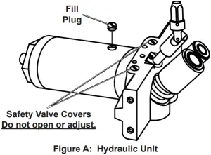
- With the Jack fully lowered, remove both Screws on the end of the Cover Plate that is closer to the Saddle. Swing the Cover Plate open. See Figure A.
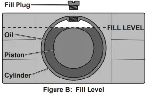
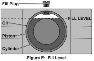
- Remove the Fill Plug on top of the Cylinder. Check that the oil level inside the Cylinder is at the top of the Piston. See Figure B.
- Insert the Handle into the Handle Socket to operate the Release Valve.
- Turn the Handle counterclockwise to open the valve.
- Pump the Handle up and down quickly 10-15 times to force air from the system.
- Replace the Fill Plug, close the Cover Plate, and reinstall the Screws.
Adding Oil
NOTICE: To prevent damage and premature wear, use only 22 viscosity, non-detergent hydraulic jack oil.
- With the Jack fully lowered, remove both Screws on the end of the Cover Plate that is closer to the Saddle. Swing the Cover Plate open.
- Remove the Fill Plug on top of the Cylinder.
- Add non-detergent 22 weight hydraulic jack oil into the Fill Plug hole slowly until the oil level just reaches the top of the Piston inside the Cylinder.
- Replace the Fill Plug, close the Cover Plate, and reinstall the Screws.
Operation
Read the ENTIRE IMPORTANT SAFETY INFORMATION section at the beginning of this manual including all text under subheadings therein before set up or use of this product.
Lifting
Park vehicle on a flat, level, solid, surface safely away from oncoming traffic. Turn off the vehicle’s engine. Place the vehicle’s transmission in “PARK” (if automatic) or in its lowest gear (if manual). Set the vehicle’s emergency brake. Then, chock the wheels that are not being lifted.
- Turn the Handle counterclockwise to lower the Jack. Once the Jack is fully lowered, turn the Handle firmly clockwise to close it.
- Carefully position the Saddle of the Jack under the vehicle manufacturer’s recommended lifting point. (See vehicle manufacturer’s owner’s manual for location of frame lifting point.)
- Pump the Handle until the top of the Jack’s Saddle has nearly reached the vehicle lifting point. Position the Saddle directly under the vehicle’s lifting point.
- To lift the vehicle, pump the Handle of the Jack. Use smooth, full strokes.
- Once the vehicle is raised, slide a jack stand of appropriate capacity (not included) under a proper lifting point referred to in the vehicle owner’s manual. Always use two jack stands, position them at the same point on each side of the vehicle.
WARNING! The rated capacity of jack stands is per pair, not the individual capacities combined unless specifically noted on the product by the jack stand manufacturer. Do not exceed rated jack stand capacity. Ensure that the vehicle support points are fully seated in the saddle of both jack stands. Use a matched pair of jack stands per vehicle to support one end only. Failure to do so may result in the load suddenly falling, which may cause personal serious injury and/or property damage. - Center the vehicle’s lifting point(s) on the saddle of the jack stand(s). Set the jack stand(s) to the same height according to the manufacturer’s instructions, making sure that they lock securely into position.
- Slowly turn the Handle counterclockwise to lower the vehicle onto the saddle(s) of the jack stand(s). Then, turn the Handle firmly clockwise to close it.
Lowering
- Carefully remove all tools, parts, etc. from under the vehicle.
- Position the Saddle under the lifting point. Turn the Handle firmly clockwise and raise load high enough to clear the jack stands, then carefully remove jack stands
- Slowly turn the Handle counterclockwise (never more than 1/2 full turn) to lower the vehicle onto the ground.
- Lower the Jack completely. Then, store in a safe, dry location out of reach of children.
- To prevent accidents, turn off the tool and disconnect its power supply after use. Clean, then store the tool indoors out of children’s reach.
Maintenance and Servicing
Procedures not specifically explained in this manual must be performed only by a qualified technician.
TO PREVENT SERIOUS INJURY FROM TOOL FAILURE: Do not use damaged equipment. If abnormal noise or vibration occurs, have the problem corrected before further use.
1. BEFORE EACH USE, inspect the general condition of the tool. Check for:
● leaking hydraulic fluid,
● loose hardware obr parts,
● misalignment or binding of moving parts,
● cracked, bent or broken parts, and
● any other condition that may affect its safe operation.
ALSO, BEFORE EACH USE, thoroughly test the Jack for proper operation prior to actual use. If the Jack’s motion seems spongy or the Saddle does not lift completely, follow Bleeding instructions on page 6.
2. AFTER USE, wipe dry with a clean cloth. Then, store the Jack in a safe, dry location out of reach of children and other non-authorized people.
NOTICE: Storing the Jack in a humid area or exposing it to corrosive vapor voids the warranty.
3. Weekly – Jack Lubrication:
a. Lubricate according to the below steps using only general purpose lithium grease.
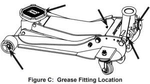
b. Inject grease into each of the 5 grease fittings.
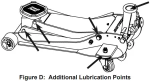
c. Lubricate the linkages and pivot points lightly.
Note: Improper or inadequate lubrication voids the warranty.
4. Change the hydraulic oil at least once every three years:
a. With the Jack fully lowered, remove both Screws on the end of the Cover Plate that is closer to the Saddle. Swing the Cover Plate open.
b. Remove the Fill Plug on the top of the Cylinder.
c. Tip the Jack to allow the old hydraulic oil to drain out of the Housing completely, and dispose of the old hydraulic oil in accordance with local regulations.
d. Turn the Jack upright. Add non-detergent 22 weight hydraulic jack oil into the Fill Plug hole slowly until the oil level just reaches the top of the Piston inside the Cylinder.
e. Replace the Fill Plug, close the Cover Plate, and reinstall the Screws.
f. Follow instructions for Bleeding Trapped Air on page 6.
Troubleshooting
TO PREVENT SERIOUS INJURY: Use caution when troubleshooting a malfunctioning jack. Stay well clear of the supported load. Completely resolve all problems before use. If the solutions presented in the Troubleshooting guide do not solve the problem, have a qualified technician inspect and repair the jack before use. After the jack is repaired: Test it carefully without a load by raising and lowering it fully, checking for proper operation, BEFORE RETURNING THE JACK TO OPERATION.
DO NOT USE A DAMAGED OR MALFUNCTIONING JACK!
| POSSIBLE SYMPTOMS | PROBABLE SOLUTION
(Jack must not be supporting a load while attempting a solution.) |
||||
| Jack will not lift at capacity | Saddle lowers under load | Pump stroke feels spongy or Saddle does not lift all the way | Handle moves up when Jack under load | Fill Plug leaking oil or Jack will not lower without a load | |
| ✖ | ✖ | Check that Release Valve is fully closed. Bleed trapped air from the hydraulics. |
|||
| ✖ | ✖ | ✖ | Valves may be blocked and may not close fully. To flush the valves:
|
||
| ✖ | ✖ | Jack may be low on oil. Check the oil level and fill if needed. See step 4 on facing page. | |||
| Jack may have air trapped in the hydraulics. Follow instructions for Bleeding Trapped Air on page 6. | |||||
| ✖ | Jack may have too much hydraulic oil inside, check fluid level and adjust if needed.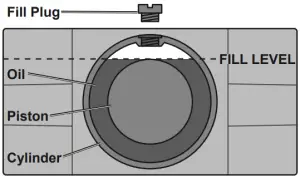 |
||||
Parts List
| Part | Description | Qty. |
| 1 | Saddle Pad | 1 |
| 2 | Saddle Screw | 1 |
| 3 | Saddle | 1 |
| 4 | Lift Arm | 1 |
| 5 | Retaining Ring 16 | 2 |
| 6 | Front Wheel | 2 |
| 7 | Front Wheel Washer | 2 |
| 8 | Lock Nut M16 | 2 |
| 9 | Grease Fitting | 5 |
| 10 | Jack Frame | 1 |
| 11 | Support Bar Bolt | 2 |
| 12 | Retaining Ring 30 | 2 |
| 13 | Nut M16 | 4 |
| 14 | Screw M5X12 | 4 |
| 15 | Washer 16 | 4 |
| 16 | Washer 12 | 4 |
| 17 | Screw M12X22 | 4 |
| 18 | Rear Caster Assembly | 2 |
| 19 | Screw M8X20 | 4 |
| 20 | Washer 8 | 4 |
| 21 | Left Handle Socket Bolt | 1 |
| 22 | Washer 18 | 1 |
| 23 | Retaining Ring 25 | 2 |
| 24 | Return Spring | 2 |
| 25 | Hydraulic Pump Unit | 1 |
| 26 | Lower Handle | 1 |
| 27 | Foam Bumper | 1 |
| 28 | Handle Lock Clip | 1 |
| 29 | Upper Handle | 1 |
| 30 | U-Joint | 1 |
| 31 | Handle Release | 1 |
| 32 | Roller Pin | 1 |
| 33 | Roller | 1 |
| 34 | Retaining Ring 14 | 1 |
| 35 | Handle Socket | 1 |
| 36 | Split Pin 4X55 | 1 |
| 37 | Hydraulic Pump Block | 1 |
| 38 | Lower Tie Rod | 1 |
| 39 | Upper Tie Rod | 1 |
| 40 | Retaining Ring 18 | 1 |
| 41 | Right Handle Socket Bolt | 1 |
| 42 | Cover Plate | 1 |
| 43 | Support Bar | 2 |
| 44 | Fill Plug | 1 |
PLEASE READ THE FOLLOWING CAREFULLY
THE MANUFACTURER AND/OR DISTRIBUTOR HAS PROVIDED THE PARTS LIST AND ASSEMBLY DIAGRAM IN THIS MANUAL AS A REFERENCE TOOL ONLY. NEITHER THE MANUFACTURER OR DISTRIBUTOR MAKES ANY REPRESENTATION OR WARRANTY OF ANY KIND TO THE BUYER THAT HE OR SHE IS QUALIFIED TO MAKE ANY REPAIRS TO THE PRODUCT, OR THAT HE OR SHE IS QUALIFIED TO REPLACE ANY PARTS OF THE PRODUCT. IN FACT, THE MANUFACTURER AND/OR DISTRIBUTOR EXPRESSLY STATES THAT ALL REPAIRS AND PARTS REPLACEMENTS SHOULD BE UNDERTAKEN BY CERTIFIED AND LICENSED TECHNICIANS, AND NOT BY THE BUYER. THE BUYER ASSUMES ALL RISK AND LIABILITY ARISING OUT OF HIS OR HER REPAIRS TO THE ORIGINAL PRODUCT OR REPLACEMENT PARTS THERETO, OR ARISING OUT OF HIS OR HER INSTALLATION OF REPLACEMENT PARTS THERETO.
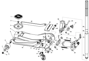
Assembly Diagram
Record Product’s Serial Number Here:
Note: If product has no serial number, record month and year of purchase instead.
Note: Some parts are listed and shown for illustration purposes only, and are not available individually as replacement parts. Specify UPC 57590 when ordering parts. Specify UPC 193175418524 when ordering parts.
Limited 3 Year Warranty
Harbor Freight Tools Co. makes every effort to assure that its products meet high quality and durability standards, and warrants to the original purchaser that this product is free from defects in materials and workmanship for the period of 3 years from the date of purchase. This warranty does not apply to damage due directly or indirectly, to misuse, abuse, negligence or accidents, repairs or alterations outside our facilities, criminal activity, improper installation, normal wear and tear, or to lack of maintenance. We shall in no event be liable for death, injuries to persons or property, or for incidental, contingent, special or consequential damages arising from the use of our product. Some states do not allow the exclusion or limitation of incidental or consequential damages, so the above limitation of exclusion may not apply to you. THIS WARRANTY IS EXPRESSLY IN LIEU OF ALL OTHER WARRANTIES, EXPRESS OR IMPLIED, INCLUDING THE WARRANTIES OF MERCHANTABILITY AND FITNESS. This warranty gives you specific legal rights and you may also have other rights which vary from state to state.
26541 Agoura Road · Calabasas, CA 91302 · 1-888-866-5797