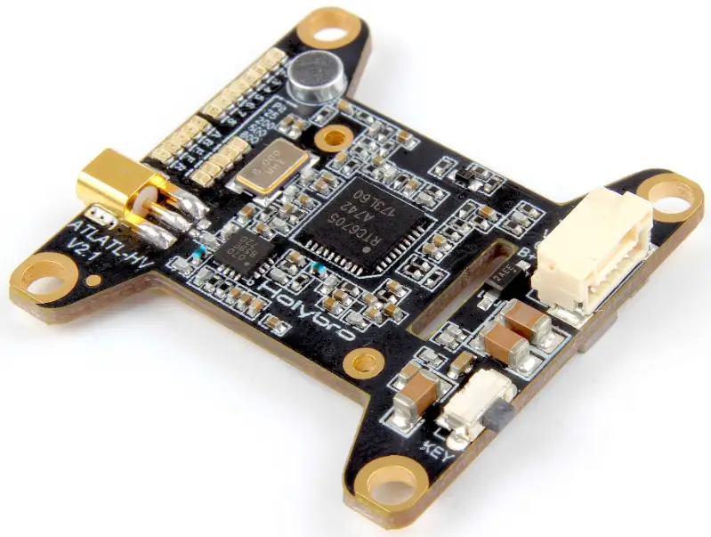

Atlatl HV V2
5.8G FPV Video Transmitter![]()
User Manual & Installation Guide

Overview
Features
- Compatible with all major FPV receivers from vendors such as Fatshark, ImmersionRC, etc.
- Supports the standard 40-channel set: band A, B, E, Fatshark, and Raceband.
- SmartAudio input allows remote control by the flight controller. Change channel, transmit power, and more from Betaflight OSD, flight controller USB port, Taranis Lua Script, and more.
- All parameters are controllable via push-button on the side of the unit, for cases where SmartAudio is not used.
- MMCX connector is durable and easy to use. Rated for 100’s of mating cycles. Easy and quick antenna changes. No more ripped-off UFL connectors.
- LED indicators for channel, band, and power. Allows easy check of VTX parameters simply by glancing at the quad.
- Variable transmit power from 25 mW to 800 mW. Use 25 mW for a race and then easily switch to 800 mW for freestyle.
- 0.5 mW True Pit Mode allows you to power up safely without the risk of knocking other pilots out of the air.
- Built-in microphone, so you can listen to your motors while you fly, no matter how far away you fly.
- Standard 36mm form factor allows you to mount the Atlatl directly on your flight controller stack.
Specifications
- Output Power: 0.5 mW (pit mode), 25 mW, 200 mW, 500 mW, 800 mW
- Audio: 6.5 MHz Mono
- Antenna Connector: MMCX
- Input Voltage: 7 to 28 volts (2-6S LiPo) with absolute maximum of 42 volts
- Dimensions: 35x25x7mm (Includes USB height)
- Mounting Holes: Standard 30.5mm square to the center of holes
- Weight: 9.3g
Warranty and Return Policy
If you believe that your Atlatl is defective, please contact us. If we determine that the product is defective, it will be repaired or replaced at no charge to you. We may ask you to send your Atlatl to our service center for examination or repair. Shipping costs are your responsibility. Returned items should include the original packaging and all accessories. If the product is damaged or defective, we will repair or replace it. Refunds are only given when a product is lost by the shipping company. The refund amount is limited to the price of the product. Shipping costs are never refundable.
Contact us at:
• Email: [email protected]
• Facebook Page: Holybro
Pinout Diagram and Channel Table
| Pin | Color | Function |
| B+ | Red | Input Voltage (7-42 volts) |
| G | Black | Ground |
| VI | Yellow | Video In (from a camera) |
| T | Blue | SmartAudio Input |
| 1 | 2 | 3 | 4 | 5 | 6 | 7 | 8 | ||
| A | Band A | 5865 | 5845 | 5825 | 5805 | 5785 | 5765 | 5745 | 5725 |
| 13 | Band B | 5733 | 5752 | 5771 | 5790 | 5809 | 5828 | 5847 | 5866 |
| E | Band E | 5705 | 5685 | 5665 | 5645 | 5885 | 5905 | 5925 | 5945 |
| F | IRC/FS | 5740 | 5760 | 5780 | 5800 | 5820 | 5840 | 5860 | 5880 |
| C | RaceBand | 5658 | 5695 | 5732 | 5769 | 5806 | 5843 | 5880 | 5917 |
Installation Guide
The Atlatl is designed to be installed in your flight controller stack. It can be installed above or below your FC using the same type of M3 nylon standoffs that are used to mount the FC itself. Wiring up the Atlatl is not complicated.
- Insert the JST-GH connector into the receptacle on the Atlatl.
- Solder the red wire to the voltage source for the Atlatl. The Atlatl can run off of battery voltage directly (7 to 28 volts, 2S to 6S). There is no need to run the Atlatl off of a voltage regulator and in fact, this sometimes produces worse video quality. We recommend powering the Atlatl directly from battery voltage and only try regulator or filtered supply if you have video noise.
- Solder the black wire to a ground pad. Video noise will be minimized if you solder your Atlatl ground wire and your FPV camera’s ground wire to the same pad. Twist them together and tin them before soldering them both to the same pad.
- Connect the Atlatl’s yellow wire to the video signal wire of your FPV camera. The camera’s video wire will usually be yellow as well. You can directly solder the two wires together, or you might have a PDB or FC with a “Video In” and “Video Out” pad. In that case, solder the camera’s video wire to “Video In” and Atlatl’s video wire to “Video Out”.
- The Atlatl can be remote-controlled using the SmartAudio protocol. This is the recommended use of the Atlatl. To use this feature, solder the Atlatl’s blue wire to the TX pad of the UART on your flight controller that will be used for this feature. See your FC’s documentation for help deciding which UART to use.
- In Betaflight or Cleanflight, go to the Ports tab. Enable SmartPort protocol on the UART that you are using to remote-control the Atlatl (the UART whose TX pad you soldered the blue wire to). Do not enable any other function on this UART. Each UART must have only one function active at a time.
![]()
Using The OSD
If you are using a Betaflight Flight Controller with Betaflight OSD, you can manage Atlatl’s transmit power and channel from within the OSD.
![]()
The graphics above show the stick command to bring up the OSD menu. The stick command is throttle centered, yaw left, pitch forward. The exact stick command, therefore, depends on which mode your transmitter sticks are in.
In the OSD menu, use pitch up/down to move the cursor between menu items. When a menu option has a > symbol to the right of it, this indicates that it contains a sub-menu. Rollright will enter the sub-menu. For example, in the screen to the right, moving the cursor to “Features” and then moving the roll stick to the right will enter the “Features” sub-menu.
![]()
To manage the Atlatl, enter the “Features” menu. From there, enter “VTX SA”
![]() The screen to the right shows the current vTX settings. From here, you can change the frequency band, channel, and power level of the video transmitter. After making the changes, move the cursor to “Set” and press roll-right to confirm the settings.
The screen to the right shows the current vTX settings. From here, you can change the frequency band, channel, and power level of the video transmitter. After making the changes, move the cursor to “Set” and press roll-right to confirm the settings.
Functions
Channel-Change Button
The Atlatl can be configured via either SmartAudio or the channel change button. If you have SmartAudio enabled in Betaflight, then the button cannot be used. If you prefer to use the button, you must disable SmartAudio in Betaflight.
Here is how to use the button:
- To change the channel, hold down the button for 2 seconds until the Channel LED blinks. You are now in channel select mode. Press the button one time to advance the channel.
- To change the band, first, go into channel select mode. From channel select mode, hold down the button for 2 seconds until the Band LED blinks. You are now in band select mode. Press the button one time to advance through the bands.
- To change power, first, go into band select mode. From band select mode, hold down the button for 2 seconds until the Power LED blinks. You are now in power select mode. Press the button one time to advance through the power options.
- From power select mode, hold down the button for 2 seconds to exit configuration and return to normal operation.
Pit Mode
Have you ever powered up your copter, only to have one of your friends start shouting and crash? Your video transmitter was on the same channel he was on, or even a nearby channel, and your signal were so loud that it overpowered his own. This is commonly referred to as being “stomped on”, and it’s a big problem any time more than one person is flying together. Even if you are not on the same channel as somebody else, you can stomp on them if you are too close to them Pit Mode helps to prevent you from stomping on other pilots. When the transmitter is in Pit Mode, it will only transmit at very low power. Within a short distance, you will be able to see your own copter’s transmission, but other pilots who are further away, won’t be affected.
To put the Atlatl into Pit Mode, hold down the button while you plug in your battery. This will cause the Atlatl to power up in Pit Mode. If you’re flying with friends, it’s a good idea to make a habit of this, to ensure that you don’t stomp on any of them when you power up.
When the Atlatl is in Pit Mode, you can change the channel, band, and power settings. These will take effect when you power cycles the board. This allows you to configure the Atlatl without stomping on other pilots who are already in the air.
Always follow best practices for frequency assignment when flying with other pilots. Never power up near other pilots, even if you think the channel is clear. Neverland your copter near to other pilots either. Always power up, take off, and land, at least 20-30 feet away from pilots who are flying.