![]()
VENTILATION BATH FAN
MODEL 7107-03HW
Homewerks.com
 Questions, problems, missing parts? Before returning to the store, call our customer service department at 1-877-319-3757, 7:30 a.m. – 4:30 p.m., CST, Monday – Friday.
READ AND SAVE THESE INSTRUCTIONS
UL COMPLIANCE
Ventilation Fan Motor Wheel Assembly B is combined into Ventilation Fan Motor Housing B-1 which is mounted into the ceiling opening.
These components comply with UL File 507: section 10.6, section 62.2.3, section 62.4.1, and section 64A.9.
LIMITED 3-YEAR WARRANTY
If the fan fails due to a defect in materials or workmanship at any time during the first THREE years of ownership, the manufacturer will replace it free of charge, postage-paid at their option. This warranty does not cover products that have been abused, altered, damaged, misused, cut or worn. This warranty does not cover use in commercial applications. Use only manufacturer-supplied genuine warranty repair replacement parts to repair this fan. Use of non-genuine repair parts will void your warranty. The manufacturer DISCLAIMS all other implied or expresses warranties including all warranties of merchantability and/or fitness for a particular purpose. As some states do not allow exclusions or limitations on an implied warranty, the above exclusions and limitations may not apply. This warranty gives you specific legal rights, and you may have
other rights that vary from state to state. This warranty is limited to the replacement of defective parts only. Labor charges and/or damage incurred during installation, repair, replacement as well as incidental and consequential damages connected with the above are excluded. Any damage to this product as a result of neglect, misuse, accident, improper installation or use other than the purpose SHALL VOID THIS WARRANTY. Shipping costs for return products as part of a claim on the warranty must be paid for by the customer. Inquiries regarding warranty claims can be directed to 1-877-319-3757, 7:30 a.m. – 4:30 p.m., CST, Monday – Friday.
PRODUCT SPECIFICATIONS
| Airflow: 110 CFM |
| 120V, 60Hz |
| Duct diameter: 4 in. |
| Sound output: 1.0 sone |
| Motor power consumption: 30W |
| Weight: 14.14 lbs. |
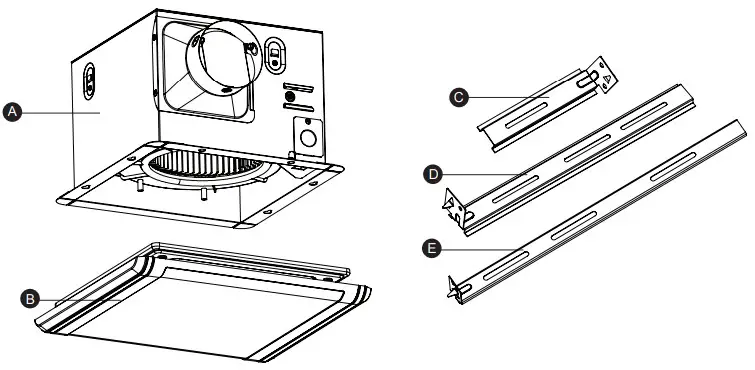
PACKAGE CONTENTS
| PART | DESCRIPTION | 1 |
| A | Fan Housing | 1 |
| B | Grille | 1 |
| C | Suspension Bracket | 1 |
| D | Suspension Bracket | 1 |
| E | Suspension Bracket | 1 |
HARDWARE INCLUDED (not actual size)
Please read and understand this entire manual before attempting to assemble, operate or install the product.
- Always disconnect the power supply prior to servicing the fan, motor or junction box.
- Follow all local building, safety, and electrical codes as well as NEC (National Electrical Code) and OSHA (Occupational Safety and Health Act).
- Electric Service supply must be 120 volts, 60 hertz.
- This product must properly connect to the grounding conductor of the supply circuit.
- Do not bend or kink the power wires.
- Do not use this fan with any solid-state control device, such as a remote control, dimmer switch, or certain timers. Mechanical timers are not solid state devices.
- Do not install in a ceiling with insulation greater than R40.
- Ductwork should be installed in a straight line with minimal bends.
- Ductwork size must be the same size as the discharge and should not be reduced. Reducing the duct size may increase fan noise.
 CAUTION
- For general ventilating use only. Do not use to exhaust hazardous or explosive materials and vapors.
- Not for use in kitchens.
- To reduce the risk of injury to persons, install the fan at least 7 feet (2.1m) above the floor.
WARNING: To reduce the risk of fire, electric shock, or injury to persons, observe the following:
- Use this unit in the manner intended by the manufacturer. If you have any questions, please call customer service.
- Before servicing or cleaning the unit, switch the power off at the service panel and lock the service disconnecting means to prevent the power from being switched on accidentally. When the service disconnecting means cannot be locked, securely fasten a prominent warning device, such as a tag, to the service panel.
- Installation work and electrical wiring must be done by a qualified person(s) in accordance with all applicable codes and standards, including fire-rated construction.
- Sufficient air is needed for proper combustion and exhausting of gases through the flue (chimney) of fuel-burning equipment to prevent back-drafting. Follow the heating equipment manufacturer´s guidelines and safety standards such as those published by the National Fire Protection Association (NFPA), and the American Society for Heating, Refrigeration and Air Conditioning Engineers (ASHRAE), and local code authorities.
- When cutting or drilling into the wall or ceiling, do not damage electrical wiring and other hidden utilities.
- Ducted fans must always be vented to the outdoors.
- If this unit is to be installed over a tub or shower, it must be marked as appropriate for the application and be connected to a GFCI (Ground Fault Circuit Interrupter)-protected branch circuit.
- This ventilation fan is intended to be installed at least 3 ft. 3-1/4 in. (1 m) from the showerhead when installing over a bathtub or shower. Installation within a shower stall is not recommended for this unit unless the 3 ft. 3-1/4 in. (1 m) distance can be met.
CAUTION: Installation of this unit requires the power to be OFF until installation is complete. If you encounter issues with the unit not powering up, please review the troubleshooting section of the instruction manual.
If you require additional assistance, please call 1-877-319-3757, 7:30 a.m. – 4:30 p.m., CST, Monday – Friday. DO NOT RETURN TO THE STORE.
PREPARATION
Before beginning the assembly of the product, make sure all parts are present. Compare parts with package contents list and hardware contents. If any part is missing or damaged, do not attempt to assemble, install or operate the product. Contact customer service for replacement parts at 1-877-319-3757, 7:30 a.m. – 4:30 p.m., CST, Monday – Friday.
Tools Required for Assembly (not included): Hammer, Flathead Screwdriver, Wire Connectors, Nails, Duct Tape, Phillips Screwdriver, and Utility Knife or Drywall Saw.
Helpful Tools (not included): Electric Drill, Drill Bits
WARNING: RISK OF ELECTRIC SHOCK. Ensure the electricity to the wires you are working on is shut off. Either remove the fuse or turn off the circuit breaker before removing the existing bath fan or installing the new one.
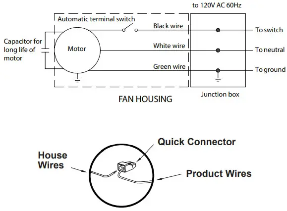
Before removing your current ventilation fan, verify the wall switch box has the required wires necessary for this installation. These supply wires are power (black) and neutral (white), as shown in the wiring diagram below. If you do not see both of these wires, consult a licensed electrician.
Check the area above installation location to be sure that wiring can run to the planned location and that ductwork can be run and the area is sufficient for proper ventilation.
Inspect ductwork and wiring before proceeding with the installation.
Before installation, provide inspection and future maintenance access at a location that will not interfere with installation work.
You may need the help of a second person to install this fan; one person on the attic side and one on the room side.
Installation may vary depending on how the previous bath fan was installed. Supplies necessary for the installation of your bath fan are not all included; however, most are available at your local home improvement or hardware store.
DIMENSIONS
| Ceiling Opening (L) | Ceiling Opening (W) | Ceiling Opening (H) |
| 10-13/16 in. | 10-1/2 in. | 8-1/2 in. |
| 10-1/4 in. | 10-1/4 in. | 8 in. |
WIRING
All wiring must be connected for full functionality.
WARNING: Wiring must comply with all applicable electrical codes. Turn off power before removing or installing connectors.
WARNING: COPPER TO COPPER ONLY. Do not use aluminum wire.
![]() CAUTION: The accessory part (quick connector) should meet the installation instructions below.
CAUTION: The accessory part (quick connector) should meet the installation instructions below.
 NOTE: The connector is reusable on solid wires of the same wire gauge or smaller. Do not reuse the connector on stranded wires.
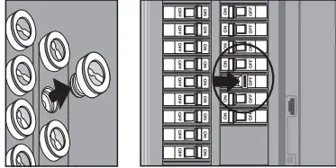
- Strip wires 3/8 in. – 1/2 in.
- Grip the wire firmly and push the stripped end of the wire into the open port of the connector. Use only one conductor per port.
- Verify the stripped end of the wires is fully inserted to the back of the connector.
CAUTION: Wiring maximum temperature rating 221˚F (105˚C). 600V maximum for building wiring and 1,000V maximum for signs and light fixtures. The acceptable wire range is 18-16 AWG Sol. Cu.
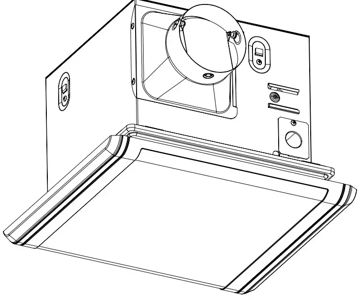
TYPICAL INSTALLATION
The ducting from this fan to the outside of the building has a strong effect on the airflow, noise, and energy use of the fan. Use the shortest, straightest duct routing possible for best performance, and avoid installing the fan with smaller ducts than recommended. Insulation around the ducts can reduce energy loss and inhibit mold growth. Fans installed with existing ducts may not achieve their rated airflow.
INSTALLATION INSTRUCTIONS
BEFORE INSTALLATION
WARNING: RISK OF ELECTRIC SHOCK! Ensure the electricity to the wires you are working on is shut off. Either remove the fuse or turn off the circuit breaker before removing the existing bath fan or installing the new one.
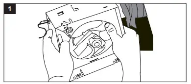
- Remove the existing fan.
If you are not replacing an existing fan, skip stepping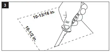
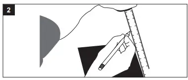
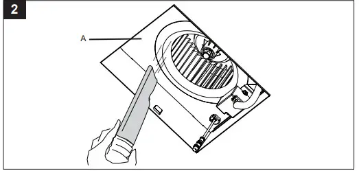
- Measure the opening to ensure it is large enough to accommodate the 10-1/4 in. x 10-1/4 in. dimensions of the new fan housing (A).
- If this fan is not replacing an old fan, cut a 10-13/16 in. x 10-1/2 in. opening for the fan housing (A).
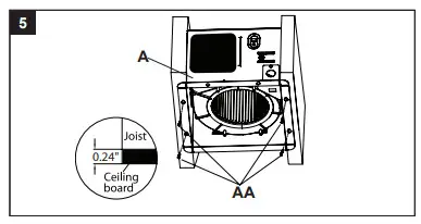
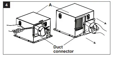
- Remove the screws that attach the duct connector to the fan housing (A), setting the screws aside to use again later. Then remove the duct connector from the fan housing (A).
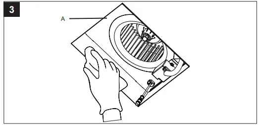
Insert the fan housing (A) into the opening cut in the drywall.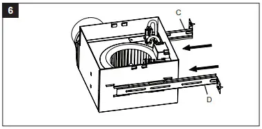 For spacing of 12 inches between ceiling joists:
- Attach the fan housing (A) to the ceiling joists using 4 long wood screws (AA). Skip to Step 12.
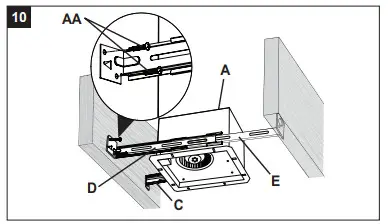
 For spacing of more than 12 inches to less than 21-1/4 inches between ceiling joists:
 - Insert suspension bracket (C) into the tabs on the duct side of the fan housing (A). Insert suspension bracket (D) into the tabs on the opposite side of the fan housing (A).
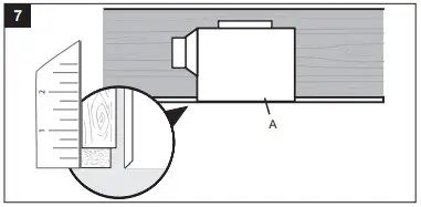
- Place the fan housing (A) next to a ceiling joist. The fan housing (A) should be level and perpendicular to the joist. Allow for thickness of ceiling board used in your application.Position the fan housing (A) so the bottom edge of the fan housing (A) is flush with the ceiling board. Do not flush mount the fan housing (A) to the bottom of the joist.
- Attach the end of a suspension bracket (C) and suspension bracket (D) to the ceiling joist using wood screws (AA). Skip to Step 12.
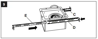
 For spacing of more than 21 inches to 24 inches between joists:
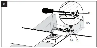
 - Insert suspension bracket (C) into the tabs on the duct side of the fan housing (A). Insert suspension bracket (D) into the tabs on the opposite side of the fan housing (A) and then slide suspension bracket (E) into the suspension bracket (D).
- Position the fan housing (A) so the bottom edge of the fan housing (A) is flush with the ceiling board. Do not flush mount the fan housing (A) to the joist.Attach the end of each of the suspension brackets (C, D, E) to the ceiling joists using wood screws (AA).
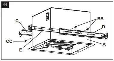
- Secure suspension brackets (D, E) to the fan housing (A) using machine screws (BB) and suspension brackets (C) to the fan housing (A) using a machine screw (CC).
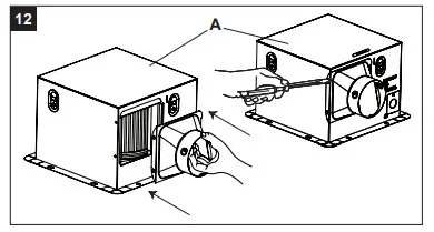
- Reattach the duct connector to the fan housing (A) with the screws that were set aside when the duct connector was removed earlier.
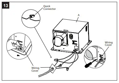
- Remove the wiring box cover from the fan housing (A). Pull the house wires through the hole in the wiring box cover. Using the quick connectors, connect the house wiring from the wall switch to the fan housing (A). 14 AWG is the smallest conductor that should be used for branch circuit wiring. Please refer to the wiring diagram on page 5 to ensure proper wire connections are made. Carefully push the wire connections into the wiring box and reattach the wiring box cover.
 CAUTION: If the house electrical wires do not match the colors from the fan wiring diagram on page 5, you must determine what each house wire represents before connecting. You may need to consult an electrical contractor to determine safety.
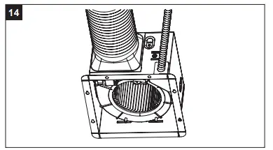
 - Connect a 4 in. circular duct to the fan housing (A), securing it with duct tape or a clamp. Vent the duct to the outside.
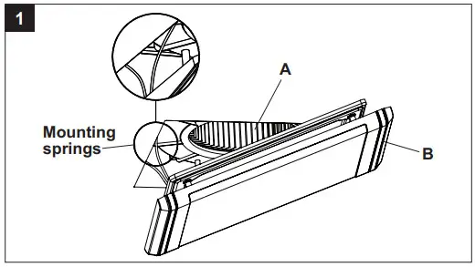
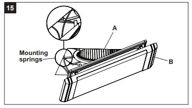
- Attach the grille (B) by pinching the mounting springs and inserting them into the narrow rectangular slots in the fan housing (A).Turn on the power source. Check the fan for any abnormal sounds or vibrations.
CARE AND CLEANING
![]() CAUTION: Before attempting to clean the fixture, disconnect the power to the fixture by turning the breaker off or removing the fuse from the fuse box.
CAUTION: Before attempting to clean the fixture, disconnect the power to the fixture by turning the breaker off or removing the fuse from the fuse box.
- See safety information before proceeding. Routine maintenance should be done at least once a year.
- Never use solvents, thinner or harsh chemicals for cleaning the fan.
- Do not allow water to enter the motor.
- Do not immerse metal parts in water.
- Do not immerse resin parts in water over 140 degrees Fahrenheit.
WARNING: RISK OF ELECTRIC SHOCK! Ensure the electricity is shut off. Either remove the fuse or turn off the circuit breaker before cleaning.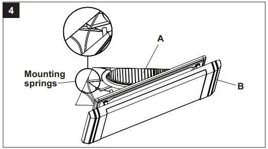
- Squeeze the mounting springs and pull the grille (B) down from the fan housing (A). Wipe grille (B) with a damp cloth.

- Remove dust and dirt from the fan housing (A) with a vacuum cleaner.
 3. Wipe the fan housing (A) with a damp cloth and wipe dry.
 4. Attach the grille (B) by pinching the mounting springs and inserting them into the narrow rectangular slots in the fan housing (A).Turn on the power source. Test the unit.
TROUBLESHOOTING
| PROBLEM | POSSIBLE CAUSE | SOLUTION |
| The fan seems louder than it
should. |
The CFM is too great for the space. | Be sure the CFM rating on the fan matches the square footage of your room. |
| The damper is damaged or not working properly. | Check the damper to ensure it is opening and closing properly. If the damper has become damaged, please call Customer Service. | |
| The bend in the duct is too close to the fan discharge. | Be sure you do not have any sharp bends in the duct within 18 in. of the fan discharge. | |
| The fan discharge is reduced to fit a smaller duct. | Use the recommended size ducting to reduce fan
noise. |
|
| The fan body is not attached securely. | Be sure the fan is securely attached to the ceilingjoists. | |
| The fan is not clearing
humidity from the room. |
There is insufficient airflow intake in the room. | Be sure a door or window is slightly ajar or open to allow airflow. The fan is not able to draw air out of the room without enough airflow. |
| There is insufficient CFM.
NOTE: Using a tissue is not the correct method for determining if the fan is perating properly. If the fan clears steam from the room within approximately 15 minutes of completing your shower, then the fan is operating properly. |
Be sure the CFM rating of the fan matches thesquare footage of your room. |