![]() HZ322 TrueZONE®
HZ322 TrueZONE®
Zone Panel Professional Installation Guide

SPECIFICATIONS
Input Ratings:
Voltage: 18 VAC – 30 VAC 50 Hz/60 Hz transformer of 40 VA or more.
Current Draw:
Zone Panel: 7.5 VA max.
THM4000R Wireless Adapter: 2 VA max.
All VA specifications at 24 VAC.
Wiring:
18- or 20-gauge solid (not stranded) wire.
Humidity Ratings:
5% to 90% RH non-condensing.
Temperature Ratings:
Shipping: -20°F to 150°F (-29°C to 66°C)
Operating: -40°F to 165°F (-40°C to 74°C)
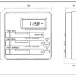
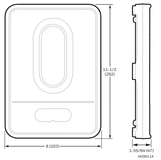
Dimensions:
See Fig. 1.
Emissions:
Complies with FCC Class B, part 15 requirements.
Need Help?
For assistance with this product please visit customer.resideo.com and/or call Zoning Hotline toll-free at 1-800-828-8367
Read before installing.
U.S. Registered Trademark. US Pat D562,261; D563,325; 7,558,648; 7,645,158; 7,693,591; 7,693,583; 7,766,246; 7,819,331; 7,904,830; 7,913,180; 7,957,839; 9,310,091 and other patents pending. Copyright © 2020 Resideo Technologies, Inc. All rights reserved.
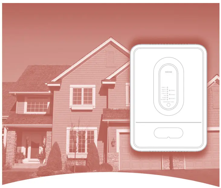
APPLICATION
The HZ322 TrueZONE® panel controls:
- Conventional gas, oil, or electric forced-air systems up to 2 stages heat and cool;
- Heat pump systems with single-stage compressor and auxiliary heat, and two-stage heat pumps with no auxiliary heat.
- 2 or 3 forced-air zones with wired thermostats, or wireless thermostats using THM4000R wireless adapter.
Please refer to TrueZONE Panel Frequently Asked Questions form 50-9694 for operating details.
customer.resideo.com
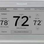
Table 1. Recommended Thermostats.
| System | Thermostat |
| Single-stage | TH1110D2009 (non-programmable) TH4110U2005 (Programmable) |
| 2H/1C conventional |
TH6220U2000 (Programmable) TH6220WF2006 (Programmable, Wi-Fi) |
| 2H/2C conventional |
TH6220U2000 (Programmable) TH6220WF2006 (Programmable, Wi-Fi) |
| 2H/1C heat pump | TH4210U2002 (Programmable) TH6210U2001 (Programmable) |
| All the above | TH6220U2000 (Programmable) TH6220WF2006 (Programmable, Wi-Fi) TH6320WF2003 (Programmable, Wi-Fi) TH8321WF1001 (Programmable, Wi-Fi) THX321WFS2001W (Programmable, Wi-Fi) |
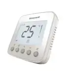
| Wireless * | TH5320R1002 TH6320R1004 TH8320R1003 |
- For RedLINK™ wireless devices, a THM4000 is required.
Table 2. Recommended Dampers.
| Type | Damper | Round | Rectangular |
| Zone | Spring-open/power-closed | ARD (8 VA) | ZD (8 VA) |
| Power-open/power-closed | MARD/RRD (2 VA) | — | |
| Bypass | Constant pressure regulating damper | CPRD (0 VA spring actuator) | — |
| Modulating automatic round damper | MARD (2 VA) | — |
Table 3. Recommended Commercial Dampers.
| Type | Actuation | Round |
| Zone | Power-open/power-closed | MARD |
| Bypass | Power-open/power-closed | MARD with SPC |
Table 4. Maximum Dampers.*
| Ambient Temp. | Maximum Damper VA per Zone |
| 100°F (38°C) | 28.8 |
| 160°F (71°C) | 16.8 |
- Use an SDCR (Slave Damper Control Relay) for additional dampers.
Maximum dampers per panel are limited by transformer size.
Ensure the transformer is large enough to power the panel (7.5 VA) and dampers.
Table 5. Accessories.
| Accessory | Description |
| 40 VA transformer* | AT140A1042* |
| 75 VA transformer | AT175A1008 |
| Discharge Air
Temperature Sensor * |
DATS C7735A1000* |
| SDCR** | Slave Damper Control
Relay |
| Wireless Adapter*** | THM4000R1000 |
| Wireless Outdoor Air Temperature Sensor*** | C7089R1013 |
| Portable Comfort Control*** | REM5000R1001 |
| RedLINK Internet
Gateway*** |
THM6000R7001 |
* Included in HZ322K kit.
** Use an SDCR (Slave Damper Control Relay) to add additional dampers to a zone to surpass the maximum Damper VA rating per Zone.
*** For RedLINK™ wireless devices, a THM4000 is required.
MOUNTING
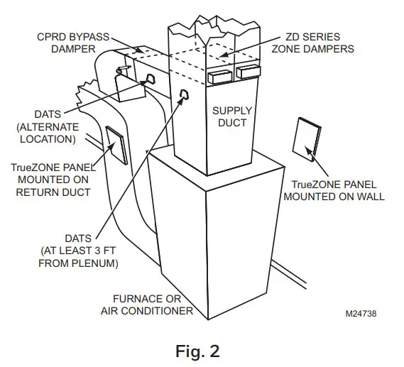
- Mount the HZ322 TrueZONE panel near the HVAC equipment; locate it on a wall, stud, roof truss, or cold air return.
NOTE: The HZ322 TrueZONE panel can be mounted in any orientation; level it for appearance only.
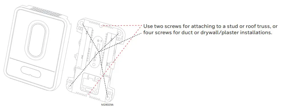
- Separate the zone panel cover from the base, and use the base as a template to drill mounting holes.
Attach the base to the wall, stud, roof truss, or duct with appropriate screws (not included).
CAUTION: Voltage Hazard.
Can cause electrical shock or equipment damage. Disconnect power before beginning installation.
Wire the entire panel before applying transformer power.
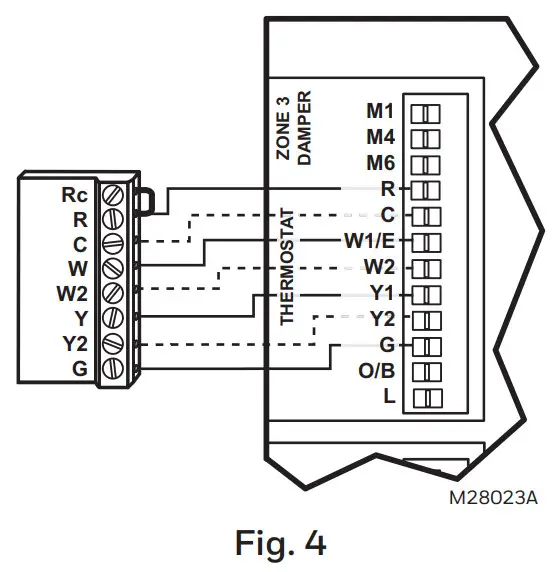
Follow these steps for wiring all systems. However, the wiring will vary depending on the equipment. For conventional systems, refer to page 5. For heat pump systems, see page 6. Wiring must comply with applicable codes, ordinances, and regulations. Use the following wiring diagrams to wire the zone panel to the thermostats and dampers. - Install thermostats using instructions provided with thermostats.
Connect thermostat to zone panel. To connect the wire to the panel, strip approximately 1/4 in. of insulation and push wire into the terminal. To release wire, press the button on to-p of the terminal. In retrofit applications, trim end of wire if not straight.
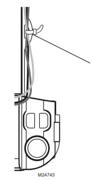 The HZ322 offers many innovations for wire management and organization: wires can be run behind the panel, through wire channels on its sides, and must be attached to a wiring anchor with a cable tie.
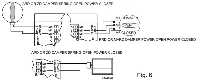
 - Install dampers using instructions provided with dampers. Connect dampers to zone panel.
NOTE: Multiple dampers can be wired in parallel.
 WIRING
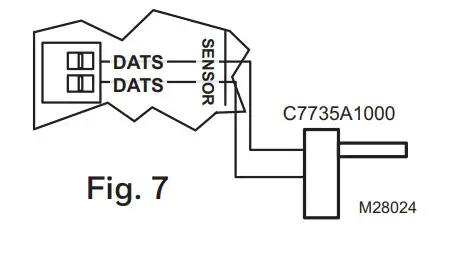
 - Connect DATS as shown. See high and low limit settings in Table 5 “Advanced Configuration” on page 8.
For the placement of DATS in the supply duct and troubleshooting assistance with the DATS, see the Discharge Air Temperature Installation InstructionsForm Number 69-1521.
- Connect the equipment as shown here and on pages 5 and 6.
For oil heat with a separate transformer for cooling, remove this jumper. For other systems leave the jumper in place and wire to the HVAC R terminal with 18 gauge solid wire.
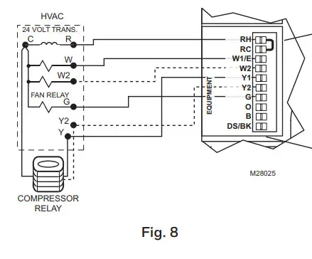 The DS/BK terminal is used with a variable-speed fan. If the HVAC equipment has a DS, BK, ODD, or DHUM terminal, wire that terminal to the HZ322 DS/BK terminal. When 2 or 3 zones are calling for cooling this terminal will be energized which will run the blower fan at the normal speed. When only 1 zone is calling for cooling the fan runs at a reduced speed which will require less air to be bypassed. Refer to HVAC equipment manufacturer instructions.
 - When a wireless thermostat, Portable Comfort Control, wireless outdoor air temperature sensor, or other RedLINK™ wireless device is used, wire the THM4000 Wireless Adapter Module to the ABCD terminals on the zone panel.
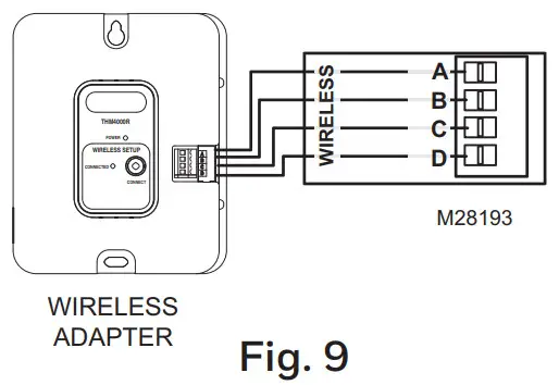 CAUTION: Only the THM4000R can be wired to the A-B-C-D terminals on the HZ322. Do not wire the A-B-C-D terminals of the THM5320R or THM5421R Equipment Interface Module to the A-B-C-D terminals on the HZ322 zone control panel. Doing so will damage the components.
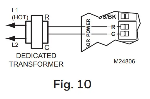
 - Connect a dedicated transformer as shown.
CONVENTIONAL
The following diagram is an overall view of wiring for a conventional system as depicted in steps 3–8.
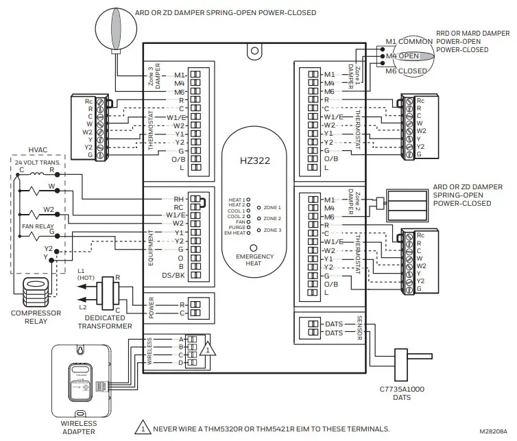
Fig. 11. Zone panel wiring—conventional.
HEAT PUMP
Use the following diagram for wiring a heat pump with electric auxiliary heat.
NOTE: You can use a conventional thermostat for a heat pump system; however, em heat can only be controlled by heat pump thermostats. The diagram below shows a heat pump thermostat used with a heat pump system.
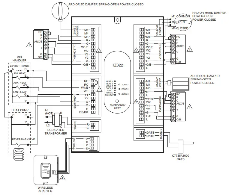
Fig. 12. Zone panel wiring—heat pump with electric auxiliary heat.
- ADD A JUMPER FROM W1/E TO W2 AT EACH ZONE.
- FOR THERMOSTATS WITH SEPARATE 0 AND B TERMINALS, ATTACH 0 FOR COOL CHANGEOVER OR ATTACH B FOR HEAT CHANGEOVER.
- IF HVAC EQUIPMENT USES THE SAME SOURCE OF HEAT FOR AUXILIARY AND EMERGENCY HEAT, JUMPER W1/E AND W2.
- ABCD TERMINALS FOR THE THM4000R WIRELESS ADAPTOR ONLY. NEVER WIRE A THM532OR OR THM5421R EIM TO THESE TERMINALS.
CONFIGURATION
To enter Configuration:
- Press the Mode button (the Config LED will light up).
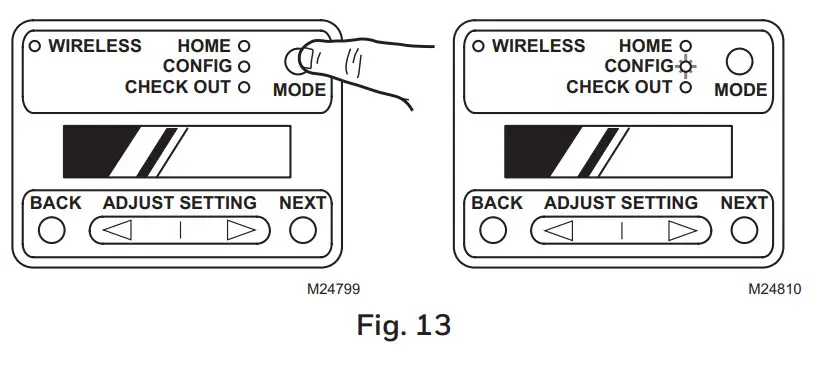
- Use the Back and Next buttons to navigate through the configuration settings. Scroll through the selection choices by using the “Adjust Setting” Left and Right arrow buttons. Pressing Next enters the selected option for that menu item and advances to the next menu.
- The flow chart below illustrates basic zone panel configuration. For additional configuration, see Advanced Configuration on page 8. The label on the inside cover of the HZ322 Zone Panel also contains configuration information.
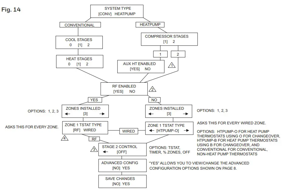 1. PANEL WILL NOT ASK IF YOU HAVE AUX HEAT WHEN 2 COMPRESSOR STAGES ARE SELECTED. THE HZ432 IS REQUIRED FOR A 3H/2C HEAT PUMP.
2. SET TO “YES” IF WIRELESS (RADIO FREQUENCY) THERMOSTATS AND THM4000R ADAPTER ARE USED.
3. SHOWN IF COMPRESSOR STAGES OR HEAT STAGES IS SET TO 2, OR AUX HT ENABLED IS SET TO “YES”
CONNECT WIRELESS DEVICES - RF MEANS “WIRELESS THERMOSTAT”
Press the Mode button until the Wireless LED lights up. The TrueZONE must be configured for wireless devices to select Wireless mode.
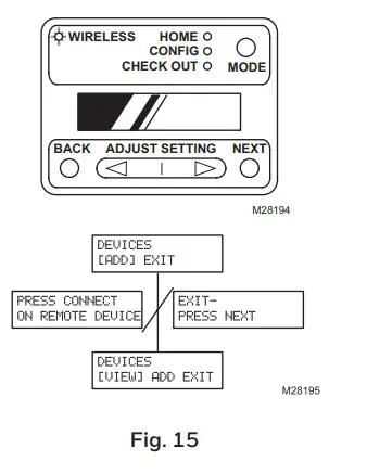 Press Next to add devices.
While the display alternates the Press Connect and Exit screens, push the Connect button(s) on the wireless device(s).
-OR
Follow the instructions that came with the wireless device(s). Press Next to exit.
ADVANCED CONFIGURATION
Use the Adjust Setting, Next, and Back buttons to configure the zone panel. See the Configuration section on page 7 for instructions on using these buttons.
Table 6. Advanced Configuration.
| Menu Name | Menu Title (LCD top line) | Menu Options (LCD bottom line; defaults in bold) | Menu option description | Notes: |
| Heat Fan | HEAT FAN
CONTROL |
[HVAC] PANEL | Fan control by HVAC | In heat mode, fan controlled by HVAC or
turned on by panel in call for heat. |
| HVAC [PANEL] | Fan control by Panel | |||
| Stage 2 Timer | STAGE 2 TIMER | [5 MIN] > – < [60 MIN]
[5 MIN] > |
5 minutes–60 minutes | A number of minutes to delay before engaging second stage. |
| Purge Timer | PURGE TIME | [2] 3.5 5 MIN | 2.0 minutes | A number of minutes panel will purge the following call for heat or cool. |
| 2 [3.5] 5 MIN | 3.5 minutes | |||
| 2 3.5 [5] MIN | 5.0 minutes | |||
| Purge Fan | FAN IN PURGE | [HVAC] PANEL | Fan control by HVAC | Fan controlled by HVAC or panel during the purge. |
| HVAC [PANEL] | Fan control by Panel | |||
| Purge Dampers | PURGE DAMPERS | [UNCHANGD] OPEN | Dampers Unchanged | Damper position unchanged or all dampers open during the purge. |
| UNCHANGED [OPEN] | Dampers All Open | |||
| Auto Changeover Delay | CHANGEOVER DELAY | [15] 20 30 MIN | 15 minutes auto changeover timer | A number of minutes to delay auto changeover when one zone is calling for heat and another is calling for cooling. |
| 15 [20] 30 MIN | 20 minutes auto changeover timer | |||
| 15 20 [30] MIN | 30 minutes auto changeover timer | |||
| DATS Enabled | DISCHARGE SENSOR | [NO] YES | Disabled | Enables or disables DATS. If Disabled, the Multistage DATS Inhibit setting is Disabled. |
| NO [YES] | Enabled | |||
| DATS High Limit | DAT HIGH LIMIT | [110 F] > – < [180 F] < [160 F] > |
110 deg F–180 deg F | For furnace systems, high limit should be set approximately 15 degrees below the furnace high limit setting. |
| DATS Low Limit | DAT LOW LIMIT | [30 F] > – < [60 F]
< [40 F] > |
30 deg F–60 deg F | Low-temperature limit. |
| OT Temp Enabled* | OT SENSOR | [NO] YES | Disabled | Enables or disables wireless outdoor temperature sensors. If Disabled, the Multistage OT Temp Lockout setting is Disabled. |
| NO [YES] | Enabled | |||
| OT Trip Point for | OUR LOCKOUT | [0 F] > – < [50 F] | 0 deg F–50 deg F | Above this temperature 2nd stage heat is |
| Multistage Lockout | TEMP | < [50 F] > | locked out. | |
| Multistage DATS Inhibit | DAT MSTG INHIBIT | NO [YES] | Enabled | Allow panel to downstage multistage equip- ment when near DATS high or low limit. |
| [NO] YES | Disabled | |||
| LCD Contrast Adjust | LCD CONTRAST | [1] > – < [10] < [5]> |
Contrast value 1–10 | Sets LCD display contrast for ease of viewing. The lowest contrast is 1, highest contrast is 10. |
| Save Changes | SAVE CHANGES? | [NO] YES | Disabled | Saves or rejects the configuration settings. |
| NO [YES] | Enabled |
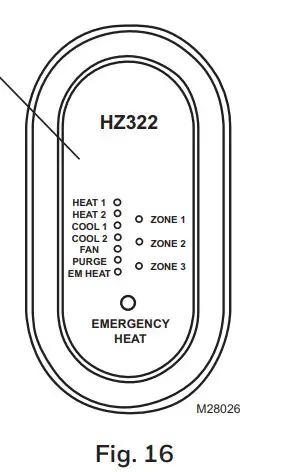
OPERATION
The HZ322 TrueZONE panel contains an LED display that communicates system and zone status. The LEDs indicate the following information.
 Much of this information, as well as configuration information, is listed on the label on the inside of the HZ322 cover. For users who prefer French or Spanish labels, they are provided in form 69-2199FS. Cut them out and attach them to the inside of the HZ322 cover.
Table 7. LED Operation.
| LED | Description |
| HEAT 1 | Solid when in heat stage 1. Blinking when DATS high limit mode has been reached. |
| HEAT 2 | Solid when in heat stage 2. Blinking when stage 2 is locked out due to DATS or OT. |
| COOL 1 | Solid when in cool stage 1. Blinking when DATS low limit mode has been reached. |
| COOL 2 | Solid when in cool stage 2. Blinking when stage 2 locked out due to DATS. |
| PURGE | Solid when in the purge (at power-up and after a call for heat or cool). Blinking when the DATS sensor has failed, or the wires are shorted or open. Will blink for 3 minutes at power-up if DATS is not present. |
| FAN | Solid with a call for the fan. |
| EM HEAT | Solid when in emergency heat mode. This light does not indicate a call for heat. Emergency heat will only run when both HEAT and EM HEAT are lit. |
| ZONE 1, 2, 3 | Solid green when open or opening. Solid red when closed or closing. Blinking amber when the damper VA exceeds the specified zone VA or there is a damper or thermostat short circuit (circuit breaker trip). |
CHECKOUT
To enter Checkout, with the zone panel cover off, press the Mode button until the Check out LED lights up. Use the Adjust Setting and Next buttons to work through the checkout menu as listed below. See the Configuration section on page 7 for instructions on using these buttons.
Steps 3–10 cycle through heating and cooling stages and open and close dampers to verify proper operation of the equipment and dampers. These steps energize the equipment and damper terminals.
Steps 11–14 verify thermostat operation and correct wiring. This is done by making the thermostats call for heat or cool and viewing the active wires as displayed on the LCD screen. This is a useful way to troubleshoot which thermostat terminals are actually energized on each zone.
Table 8. Checkout.
| Checkout Step | Line 1 display | Line 2 Display | Notes: | |
| 1. | The display shows OT* | OUR SENSOR VAL | current OT temp (dynamic) | All zone dampers open, all other relays OFF. |
| 2. | The display shows DATS** | DAT SENSOR VAL | current DATS (dynamic) | |
| 3. | Heat stages test | TEST HEAT | [OFF] 1 2 | Heat turns on (fan also turns on if configured for the fan on in heat). |
| 4. | EM Heat stages test | TEST EMERG HEAT | [OFF] 1 2 | Emergency heat turns on (fan also turns on). |
| 5. | Cool stages test | TEST COOL | [OFF] 1 2 | Cooling turns on (fan also turns on). |
| 6. | Fan Test | TEST FAN | [OFF] ON | Fan cycles on and off. |
| 7. | Damper 1 test | TEST Z1 DAMPER | [OPEN] CLOSED | Cycles damper position with the fan on. |
| 8. | Damper 2 test | TEST Z2 DAMPER | [OPEN] CLOSED | Cycles damper position with the fan on. |
| 9. | Damper 3 test | TEST Z3 DAMPER | [OPEN] CLOSED | Cycles damper position with the fan on. |
| 10. | View Tstat1 inputs | ZONE1 STAT INPTS | Displays active Tstat1 terminals or displays wireless thermostat operation | Tests thermostat wiring with HVAC off. |
| 11. | View Tstat2 inputs | ZONE2 STAT INPTS | Displays active Tstat2 terminals or displays wireless thermostat operation | Tests thermostat wiring with HVAC off. |
| 12. | View Tstat3 inputs | ZONE3 STAT INPTS | Displays active Tstat3 terminals or displays wire-less thermostat operation | Tests thermostat wiring with HVAC off. |
| 13. | Exit checkout mode? | EXIT CHECKOUT? | (NEXT = EXIT) | |
* Wireless outdoor Sensor C7089R and Wireless Adapter THM4000R required for OT Temperature.
**Discharge Air Temperature Sensor C7735A required to display Discharge Air Temperature.
WARRANTY
Resideo warrants this product, excluding battery, to be free from defects in workmanship or materials, under normal use and service, for a period of five (5) years from the date of first purchase by the original purchaser. If at any time during the warranty period the product is determined to be defective due to workmanship or materials, Resideo shall repair or replace it (at Resideo’s option).
If the product is defective,
- return it, with a bill of sale or other dated proof of purchase, to the place from which you purchased it; or
- call Resideo Customer Care at 1-800-828-8367. Customer Care will make the determination whether the product should be returned to the following address:
Resideo Return Goods, 1985 Douglas Dr. N., Golden Valley, MN 55422, or whether a replacement product can be sent to you.
This warranty does not cover removal or reinstallation costs. This warranty shall not apply if it is shown by Resideo that the defect was caused by damage that occurred while the product was in the possession of a consumer.
Resideo’s sole responsibility shall be to repair or replace the product within the terms stated above. RESIDE SHALL NOT BE LIABLE FOR ANY LOSS OR DAMAGE OF ANY KIND, INCLUDING ANY INCIDENTAL OR CONSEQUENTIAL DAMAGES RESULTING, DIRECTLY OR INDIRECTLY, FROM ANY BREACH OF ANY WARRANTY,
EXPRESS OR IMPLIED, OR ANY OTHER FAILURE OF THIS PRODUCT.
Some states do not allow the exclusion or limitation of incidental or consequential damages, so this limitation may not apply to you.
THIS WARRANTY IS THE ONLY EXPRESS WARRANTY RESIDE MAKES ON THIS PRODUCT. THE DURATION OF ANY IMPLIED WARRANTIES, INCLUDING THE WARRANTIES OF MERCHANTABILITY AND FITNESS FOR A PARTICULAR PURPOSE, IS HEREBY LIMITED TO THE FIVE-YEAR DURATION OF THIS WARRANTY. Some states do not allow limitations on how long an implied warranty lasts, so the above limitation may not apply to you.
This warranty gives you specific legal rights, and you may have other rights which vary from state to state. If you have any questions concerning this warranty, please write Resideo Customer Care, 1985 Douglas Dr, Golden Valley, MN 55422 or call 1- 800-828-8367.
![]() www.resideo.com
www.resideo.com
Resideo Technologies, Inc.
1985 Douglas Drive North, Golden Valley, MN 55422 1-800-633-3991
69-2199—11 M.S. Rev. 03-20 | Printed in the United States
© 2020 Resideo Technologies, Inc. All rights reserved.
The Honeywell Home trademark is used under license from Honeywell International, Inc.
This product is manufactured by Resideo Technologies, Inc. and its affiliates.