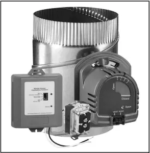
Honeywell Home W8150 Control Y8150 Fresh Air Ventilation System
FEATURES
- Designed to help meet local ventilation codes and standards, including ASHRAE 62.2-2010 standard, “Ventilation and Acceptable Indoor Air Quality in Low-Rise Residential Buildings.”
- Microcontroller optimizes the air delivery schedule to make efficient use of normal HVAC run times.
- Easy-to-use input dials allow customized ventilation for each installation.
- Test mode that includes immediate feedback to installer to confirm that air delivery requirements of selected ventilation standard are being met.
- Economical supply-only ventilation; works with forced air system.
- Can be used with other equipment, such as an HRV/ERV, for balanced ventilation.
IMPORTANT Please read these instructions and keep them in your records.
APPLICATION
The Y8150 Fresh Air Ventilation System, W8150 Fresh Air Ventilation Control provide fresh air to a home. The control operates a fresh air intake damper and, when necessary, activates the main HVAC blower to efficiently meet ASHRAE ventilation rates.
SPECIFICATIONS
Y8150 includes:
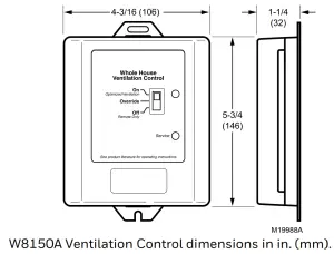
W8150A Fresh Air Ventilation Control.
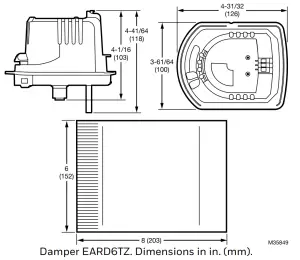
EARD6TZ Fresh Air Damper.
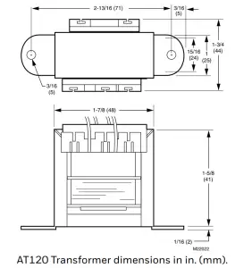
AT120 Transformer. Mounting hardware for control.
Homeowner information label.
W8150 includes:
W8150 Fresh Air Ventilation Control.
Mounting hardware for control.
Homeowner information label.
Control (W8150A):
Power Supply: 20-30 Vac, 60 Hz.
Power Consumption: 3.5 VA at 24 Vac.
Thermostat Fan Load: 10 mA resistive at 24 Vac.
Thermostat Heat Load: 10 mA resistive at 24 Vac.
Remote Terminals: 10 mA resistive at 24 Vac.
Relay Contacts: Fan:
1.5A full load, 7.5A locked rotor at 24 Vac.
Damper: 0.6A inductive, 3.1A locked rotor at 24 Vac.
Auxiliary: 0.5A inductive, 2.5A locked rotor at 24 Vac.
Damper (EARD6TZ): 24 Vac, 12 VA, 60 Hz.
Operation: Power-open, spring-closed.
Diameter: 6 in.
Transformer (AT120):
Input: 120 Vac.
Output: 27 Vac open circuit, 24 Vac full load at 20 VA.
Mounting: Foot mounted.
Temperature: -20 °F to 160 °F (-29 °C to 71 °C).
Humidity: 5 to 90% RH, noncondensing.
Input Setting Ranges:
Bedrooms: 2-5.
Area: 1000-4600 sq ft.
Vent Airflow: 40-160 cfm.
Composite Setting Resolution: +/- 12% of ASHRAE 62.2-2010, recommended ventilation for single-system setup.
AT120 Approvals: UL Component Recognized: Class 2, File No. E14881.
Location: Device can be installed in unconditioned space.
Multiple devices can be installed when operating multiple HVAC systems.
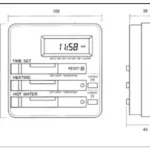
Dimensions: See device dimension diagrams.
DIMENSIONS
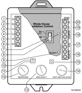
W8150 QUICK GUIDE
| No. | Name | Description | Function |
| 1 | GF | Equipment fan | Allows W8150 to pass thermostat calls and, when necessary, turn on system fan for ventilation. This should be the only connection to G on the HVAC equipment. |
| 2 | RC | 24 Vac cooling system power | Provides power to GF terminal to operate system fan, when necessary. |
| 3 | CC | 24 Vac cooling system common | Allows W8150 to monitor when system fan is energized. |
| 4 | CH | 24 Vac heating system common | Allows W8150 to monitor thermostat heat calls when W is energized. |
| 5 | W | Heating | Allows W8150 to monitor when heating is energized. |
| 6 | GT | Thermostat (or other control) fan terminal | Allows W8150 to monitor when GT is energized. All external equipment that controls the system fan should be wired to this terminal. |
| 7 | Switch | On (optimal ventilation) Override
Off (Remote Only) |
On (optimal ventilation) – W8150 ventilates, based on control settings. Override – W8150 runs ventilation continuously.
Off (Remote Only) – W8150 supplies ventilation only when there is a remote call. |
| 8 | Light | Green | Indicates device is powered and operating normally. Used in Test Mode to signal if dial settings meet chosen standard. |
| 9 | Light | Red | Indicates the device is not operating normally. Used in Test Mode to signal if dial settings do not meet chosen standard. |
| 10 | DIP1 | Ventilation limit | Choose between 60% (default) and 100% maximum fan run time allowed by W8150 for ventilation. |
| 11 | DIP2 | Ventilation standard | Choose between ASHRAE 62.2 (default) and 62-1999 ventilation standards. |
| 12 | BEDROOMS | Number of bedrooms | Used to calculate amount of ventilation necessary. |
| 13 | AREA (SQ FT) | Square footage of conditioned space | Used to calculate amount of ventilation necessary. |
| 14 | VENT AIRFLOW (CFM) | Air delivery rate through fresh air duct. | Used to calculate amount of ventilation necessary. |
| 15 | Test | Test button | W8150 checks dial and switch settings, activates ventilation for up to three minutes and provides feedback to validate if chosen standard can be met. |
| 16 | REMOTE | Remote switch (two terminals) | 24 Vac powered contacts allow a remote switch closure to call for ventilation. |
| 17 | AUX | Auxiliary (two terminals) | 24 Vac dry contacts allow W8150 to control an auxiliary device, such as exhaust fan or HRV/ERV, with a call for ventilation. |
| 18 | DAMPER | Damper (two terminals) | 24 Vac powered contacts control fresh air damper. |
| 19 | XFMR C | 24 Vac ventilation control common | Supplies power to W8150 and damper from transformer provided. |
| 20 | XFMR R | 24 Vac ventilation control power | Supplies power to W8150 and damper from transformer provided. |
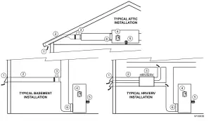
INSTALLATION
A fresh air duct and damper must be installed between the outdoors and the return side of the HVAC equipment. The W8150 control will be mounted near the HVAC system and wired between the thermostat and the fan control.
You will need…
- W8150 Fresh Air Ventilation Control.
- damper. · transformer.
- insulated ductwork.
- outdoor weather hood.
- starting collar.
- access to 120 Vac power.
- airflow measuring tool.
TIPS:
- To meet ASHRAE 62.2-2010, system must have at least a MERV 6 filter installed.
- In cold climates, balanced ventilation is recommended.
An exhaust fan or heat recovery ventilator can be used. - Humid climates may require additional dehumidification equipment.
Choosing a location…
When choosing locations for equipment, duct connections, and fresh air intake, be sure to consult local code requirements.
| Device Number | Component | Location |
| 1 | Fresh air intake | Install away from known sources of pollutants such as auto exhaust, dryer vent exhaust or chimney smoke. |
| 2 | Fresh air duct | Install between weather hood and upstream of equipment filter and downstream of any duct-mounted sensor. |
| 3 | Damper | Install damper in fresh air duct, where convenient. Optionally, install heat recovery ventilator. |
| 4 | Control | Locate the control for convenient access and for easy wire routing. |
| 5 | Transformer | Locate where convenient for line voltage connection. |
| 6 | Filter | Locate filter downstream of fresh air intake. |
Installing fresh air damper, ducting, and control…
- 1. Disconnect power from HVAC system.
- Install the weather hood, ducting, and damper following local practices. Be sure all duct and insulation seams are tightly sealed.
- Mount the transformer and control.
TIPS:
- In general, larger ducting allows higher airflow, minimizes additional fan run time and may be needed for larger homes.
- Installing a damper directly to the return duct may be convenient to support the damper and reduce ducting.
- Fresh air connection should be downstream of sensors (such as a humidistat) in return air plenum.
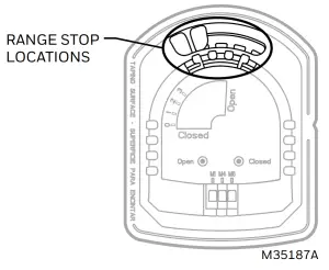
- The EARD6TZ end stops can be used to reduce the amount of airflow in the duct. To prevent complete opening, move the red tab to the desired range stop location.
Wiring the control…
 CAUTION
Electrical Hazard. Can cause personal injury or equipment damage. Disconnect power to all systems before beginning installation.
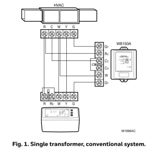
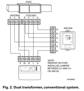
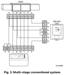
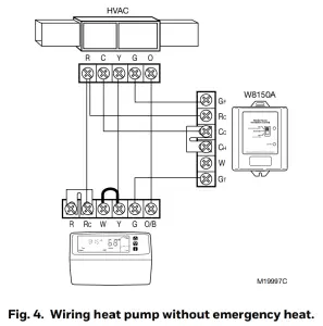
- Wire the control. See wiring diagrams in Fig. 1-10 as listed below. All wiring must comply with local codes, ordinances, and regulations.
- Reapply power to system and control.
TIP:
- Control package allows wire routing through side slots and bottom openings.
| System Hookup Diagrams | Fig. No. | Page No. |
| Single transformer, conventional | 1 | 10 |
| Dual transformer, conventional | 2 | 10 |
| Multi-stage, conventional | 3 | 10 |
| Heat pump without emergency heat | 4 | 10 |
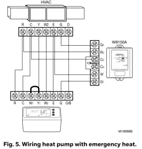
| Heat pump with emergency heat | 5 | 11 |
| Accessory Hookup Diagrams | Fig. No. | Page No. |
| Wiring with a PC8900 Thermostat | 6 | 11 |
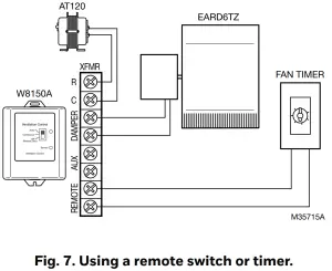
| Wiring with a remote switch/timer | 7 | 11 |
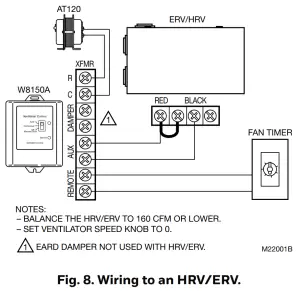
| Wiring to an HRV/ERV | 8 | 11 |
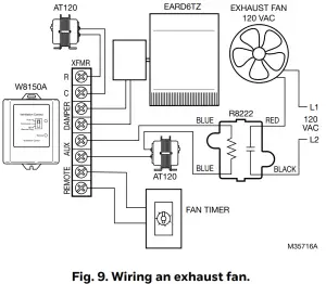
| Wiring an exhaust fan | 9 | 11 |
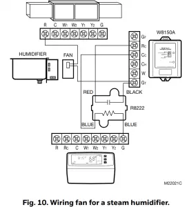
| Wiring a fan for a steam humidifier | 10 | 12 |
Measuring airflow…
- Make sure all HVAC system air filters are clean and installed.
- Push Test button:
• Control opens damper and turns on HVAC fan for three minutes.
• A red or green light is flashing; you can now measure airflow. - Follow instrument instructions for measuring airflow.
TIPS:
- You can exit the test mode at any time by pressing the test button again.
- See Conversion Table (located after wiring diagrams) for quick area and airflow setting conversions.
- For future reference, record the air flow on the inside of the device cover.
- Pitot Tubes and flow measuring stations are commonly used airflow measuring devices.
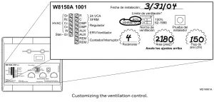
About the control settings…
Dial Settings
These settings allow the installer to customize the control to meet the ventilation requirements for the home.
Ventilation Standard
Building codes are different everywhere. The W8150 Ventilation Control can be configured to operate based on:
- ASHRAE 62.2.
- ASHRAE 62-1999
TIP:
- Clear understanding of local codes and practices is required to make sure the ventilation system is installed and configured correctly. Generally, ASHRAE 62.2 control method is recommended and can meet many existing local codes.
Code/Standard Setting General Ventilation Requirements ASHRAE 62.2 Washington State Energy Code ASHRAE 62.2 Canadian Building Code* ASHRAE 62.2 Minnesota Energy Code 62-1999 2002 International Residential Code 62-1999 *In Canada, interlocking exhaust equipment may be required for balanced ventilation.
Ventilation Limit
This setting determines the maximum amount of time that the fan runs for ventilation.
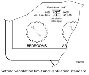
Setting ventilation limit and ventilation standard.
Setting the control…
- Be sure power is turned on.
- Set the Ventilation Standard on the control.
- Set the bedrooms dial.
- Set the area (sq ft) dial.
- Set the airflow (cfm) dial.
- Press the test button and observe the lights:
Green light is flashing.
The dial settings meet the chosen standard.
Red light is flashing.
There is not enough fresh air delivered to meet the requirements of the selected standard. See Troubleshooting section. - Record settings on the label inside the cover as shown in the diagram.
TIPS:
- Ventilation control reads new dial setting only when test button is pushed or power is cycled. To ensure dial settings are read, push test button after any changes are made.
- For single bedroom homes, set the bedrooms dial to 2 (this may result in more ventilation than the minimum required).
- For homes having more than five bedrooms and only a single ventilation system, set the bedrooms dial to 5 (this may result in less ventilation than the minimum required).
- For conditioned square feet, set area (sq ft) dial to the nearest value.
- For airflow, set airflow (cfm) dial to the nearest value. · Vaulted ceilings do not need to be considered when
setting this control. - For homes with multiple systems: Resideo
recommends a ventilation control and fresh air intake for each system. Measure ventilation airflow for each system independently. Refer to Multi-system Setup Example for further details.
CHECKOUT
In this section, make sure the ventilation system is operating correctly.
- On thermostat, set Fan switch to Auto and System switch to Off.
- Set any remote switches throughout the house in the Off position.
- On the W8150, set the control switch to Off (remote only).
- Press Test button for two seconds to enter test mode:
• A light on the control begins flashing.
• The HVAC system fan comes on.
• The damper moves to the Open position. - Press the Test button again to exit test mode:
• No lights on the control are on.
• The HVAC system fan turns off.
• The damper returns to the closed position. - Return the thermostat, ventilation control, and remote switches to the original settings.
- Refer to Troubleshooting section, if needed.
TIP:
- W8150 Ventilation Control automatically exits test mode after three minutes.
TROUBLESHOOTING
| Problem | Possible cause | What to do |
| Flashing red light during test mode (The current settings do not meet the selected ventilation requirement) | Not enough airflow |
|
| Ventilation on-time limit setting |
|
|
| Flashing red light during normal operation | Low voltage |
|
No light on ventilation control when switch set to:
|
No power to control |
|
| Device malfunction |
|
|
| HVAC fan does not come on after pressing Test button. | Wiring |
|
| HVAC system does not have power |
|
|
| HVAC fan is running all the time | Device is set to override |
|
| Remote switch is on |
|
|
| Thermostat Fan switch is in On position |
|
|
| HVAC system is running to satisfy heating or cooling requirements. |
|
|
| Ventilation limit is set to 100% ventilation limit. |
|
|
| Low ventilation air flow. |
|
|
|
Incorrectly wired. |
|
| Transformer output. |
|
|
| Damper actuator motor failure or mechanical failure. |
|
|
| Cooling compressor comes on when there is no cooling call from the thermostat. | Incorrectly wired. |
|
| Not enough airflow | Obstruction or duct size |
NOTE: After any changes to the ductwork, repeat the Measuring Air- flow section. |
WIRING DIAGRAMS
Consult thermostat Installation Instructions for alternate terminal designations.

Multi-System Setup Example
Total square feet and bedrooms should be proportionately split between the ventilation controls based on sq ft served by each system regardless of where the bedrooms are located.
Example: 5,000 sq ft, six bedrooms:
System 1:
- serves 3200 sq ft,
- two bedrooms.
- fresh air intake measured at 127 cfm.
System 2:
- serves 1800 sq ft,
- four bedrooms
- fresh air intake measured at 98 cfm.
Set W8150 for System 1:
- 3100 sq ft,
- four bedrooms
- 130 cfm.
Set W8150 for System 2:
- 1900 sq ft,
- two bedrooms
- 100 cfm.
CONVERSION TABLE
| Area | Airflow | ||
| sq ft | sq m | cfm | lps |
| 1000 | 93 | 40 | 19 |
| 1300 | 121 | 50 | 24 |
| 1600 | 149 | 60 | 28 |
| 1900 | 177 | 70 | 33 |
| 2200 | 204 | 80 | 38 |
| 2500 | 232 | 90 | 42 |
| 2800 | 260 | 100 | 47 |
| 3100 | 288 | 110 | 52 |
| 3400 | 316 | 120 | 57 |
| 3700 | 344 | 130 | 61 |
| 4000 | 372 | 140 | 66 |
| 4300 | 399 | 150 | 71 |
| 4600 | 427 | 160 | 76 |
| Airflow | ||||
| cfm | 6 in. duct (15.2 cm) | 7 in. duct (17.8 cm) | ||
| fpm | ms | fpm | ms | |
| 40 | 204 | 1.0 | 150 | 0.8 |
| 50 | 255 | 1.3 | 187 | 1.0 |
| 60 | 306 | 1.6 | 225 | 1.1 |
| 70 | 357 | 1.8 | 262 | 1.3 |
| 80 | 407 | 2.1 | 299 | 1.5 |
| 90 | 458 | 2.3 | 337 | 1.7 |
| 100 | 509 | 2.6 | 374 | 1.9 |
| 110 | 560 | 2.8 | 412 | 2.1 |
| 120 | 611 | 3.1 | 449 | 2.3 |
| 130 | 662 | 3.4 | 486 | 2.5 |
| 140 | 713 | 3.6 | 524 | 2.7 |
| 150 | 764 | 3.9 | 561 | 2.9 |
| 160 | 815 | 4.1 | 599 | 3.0 |

Resideo Technologies, Inc.
1985 Douglas Drive North, Golden Valley, MN 55422 1-800-468-1502
68-0282–11 M.S. Rev. 04-20 | Printed in United States
© 2020 Resideo Technologies, Inc. All rights reserved.
The Honeywell Home trademark is used under license from Honeywell International, Inc. This product is manufactured by Resideo Technologies, Inc. and its affiliates.