Honeywell W8835 EnviraZone Panel Instruction Manual
APPLICATION
The W8835 EnviraZone Panel controls single-stage, multistage, conventional or heat pump heat/cool equipment. It controls three zones, and is expandable up to nine zones with two additional W8703A Damper Interface Modules (DIM). For Internet access: http://yourhome.honeywell.com. For technical support, call: 1-800-828-8367.
IMPORTANT
Please read these instructions and keep them in your records.
FEATURES
- Controls up to three stages heat and two stages cooling of single-stage, multi-stage, conventional, or heat pump.
- Controls up to three zones and can be expanded up to nine zones with two W8703A DIM.
- Uses VisionPRO® IAQ or FocusPRO communicating thermostats for manual or automatic changeover by zone.
- Supports dehumidification, humidification and ventilator controls.
- Purge timer protects equipment between calls for heat or cool with choice of panel or HVAC equipmentcontrolled fan.
- System and zone damper LEDs indicate system and damper status.
- Individual zone fan control.
- Supports C7835 Discharge Air Temperature Sensor for capacity control with adjustable high and low limits and equipment failure indication.
- Controls duel fuel equipment when used with an external fossil fuel kit.
SPECIFICATIONS
Input Ratings:
Voltage: 20-30 Vac, 50/60 Hz.
Power: 11 VA nominal, Class II.
Output Ratings (dampers and HVAC equipment):
1.5A run, 200,000 cycles (30 Vac) 3.5A inrush.
1.5A run, 100,000 cycles (30 Vac) 7.5A inrush.
Humidity Ratings:
90 percent RH at 95°F, non-condensing.
Temperature Ratings:
Shipping: -20 to 120°F.
Operating: -40 to 150°F.
LED:
SYSTEM mode LEDs (5) used to communicate equipment
status:
Red Heat: Heat mode.
Green Cool: Cool mode.
Yellow Purge: Purge mode.
Green Fan: Fan mode.
Red Em Heat: Emergency Heat mode.
ZONE LEDs (3) used to communicate damper status:
Green: Dampers are open or opening.
No Color: Dampers are closed or closing.
COM LED (1) used to indicate communication status:
Flashing Green: Panel is transmitting or has received data.
No color: Communications are idle.
Dimensions: 12-3/4 in. W x 10-3/4 in. H x 1-7/8 in. D.
See Fig. 1.
Finish: W8835: Taupe cover, olive-gray base.
Mounting: Mounts with four screws (provided) through holes in cabinet back (wall anchors provided).
Wiring: Eighteen-gauge wire for all equipment and system connections.
Wiring Connections:
EnviraCom: Four terminal strips (each with three terminals labeled 1, 2, 3).
Dampers: Three terminal strips labeled M6 (Closed), M4 (Open), M1 (Common).
Transformer 1: R (hot), C (Common).
Transformer 2: T1 (hot), T2 (Common).
Equipment: Rc, Rh, W1/E, W2, W3/Aux, Y1, Y2, G, O/B.
Humidifier: HUM, HUM.
Dehumidifier: DHUM, DHUM.
Ventilator: VENT, VENT.
Thermostats: VisionPRO® IAQ TH9421 or FocusPRO THM5320C Thermostats controls single- or multi-stage conventional and heat pump equipment.
Accessories: For required accessories, see Table 2. Optional accessories include the W8735 Telephone Access Module for telephone dial-in and dial-out capability, and the W8703 Damper Interface Module to control additional zones
ORDERING INFORMATION
When purchasing replacement and modernization products from your TRADELINE® wholesaler or distributor, refer to the TRADELINE® Catalog or price sheets for complete ordering number.
If you have additional questions, need further information, or would like to comment on our products or services, please write or phone:
- Your local Honeywell Automation and Control Products Sales Office (check white pages of your phone directory).
- Honeywell Customer Care 1885 Douglas Drive North Minneapolis, Minnesota 55422-4386
In Canada—Honeywell Limited/Honeywell Limitée, 35 Dynamic Drive, Toronto, Ontario M1V 4Z9. International Sales and Service Offices in all principal cities of the world. Manufacturing in Australia, Canada, Finland, France, Germany, Japan, Mexico, Netherlands, Spain, Taiwan, United Kingdom, U.S.A.
Dampers:
See Table 1 for suggested dampers. Dampers are connected to M1 Common, M4 Open, and M6 Closed (see Fig. 5 through 8 for hookups). Connect no more than five ARD or ZD dampers to an individual zone. Connect no more than five ARD or ZD dampers to the panel when using one 40 VA transformer; connect no more than ten ARD or ZD dampers when using two 40 VA transformers. Use SDCR for additional dampers required. If using RRD dampers, refer to RRD installation instructions for maximum number of dampers.
| Motor Terminal | Damper Action |
| Common/M1 | Common |
| Open/M4 | Power Open |
| Closed/M6 | Power Close |

Fig. 1. W8835 dimensions in in. (mm).
Table 1. Recommended Dampers
| Honeywell Damper Type | Round | Rectangular |
| For systems > 2000 cfm. | MARD or RRD | For recommended dampers, call the Honeywell Zoning Hotline at 1-800-828-8367. |
| For systems <= 2000 cfm. | ARD or RRD | ZD |
Table 2. Required Accessories (Not Supplied with Panel).
|
Accessory |
Description |
Bypass Rating (cfm) |
| 40 VA transformers | AT140A1042a | — |
| High and low limit sensor | C7835A1009a | — |
| Round static pressure regulator damper | SPRD7 | 300 |
| SPRD8 | 400 | |
| SPRD9 | 600 | |
| SPRD10 | 750 | |
| SPRD12 | 1200 | |
| SPRD14 | 1800 | |
| SPRD16 | 2400 | |
| Rectangular static pressure regulator damper | SPRD12x8 | 1000 |
| SPRD12x10 | 1200 | |
| SPRD12x12 | 1400 | |
| SPRD20x8 | 1600 | |
| SPRD20x10 | 2000 | |
| SPRD20x12 | 3000 |
a Supplied in the Y8835 kits.
INSTALLATION
Mounting
 CAUTION
Equipment Damage Hazard. Do not mount W8835 inside HVAC equipment.
Mount only on wall or on cold air return.
- Mount the thermostats in each zone of the living space using the installation instructions provided with each
- Mount the dampers in the ductwork using the installation instructions provided with each
- Mount the W8835 EnviraZone Panel near the HVAC equipment; locate it on a wall or on the cold-air See Fig. 2.
- Level the W8835 for appearance
Fig. 2. W8835 mounting location.
Wiring
CAUTION
Voltage Hazard.
Can cause electrical shock or equipment damage.
Disconnect power before continuing installation. Wiring must comply with applicable codes, ordinances, and regulations.
Wiring Thermostats
Run wire from the Thermostat 1, 2, 3 terminals to the corresponding terminals on any one of the EnviraCom bus terminal sets. More than one thermostat or other communicating device can be connected to a bus terminal. See Fig. 3.
Wiring Equipment
CONVENTIONAL EQUIPMENT
Connect the first stage heat to W1/E, second stage heat to W2, and third stage heat to W3/Aux. Wire first stage cooling to Y1, and second stage cooling to Y2. See Fig. 3.
If separate HVAC equipment transformers are used for the heating and cooling systems, such as for an oil furnace, wire the heating transformer hot wire to Rh and the cooling transformer hot wire to Rc. Locate the Rh/Rc jumper above the equipment terminals and remove the jumper to expose the two pins.
HEAT PUMP EQUIPMENT
Connect the Y1 terminal to the first stage compressor, and the Y2 terminal to the second stage compressor. W3/Aux is the auxiliary heat and W1/E is the emergency heat. If emergency heat and auxiliary heat use the same piece of equipment, place a jumper from W3/Aux to W1/E and wire it to the resistive heat equipment. See Fig. 4 and 5. See Fig. 6 and 7 for two- stage heat pump equipment.

Fig. 3. Conventional equipment wiring diagram.
For dual fuel equipment using heat pump and fossil fuel, configure the panel as a heat pump and use a fossil fuel kit. Do not use the dual fuel functionality of the VisionPRO® IAQ.
Wiring HVAC Equipment
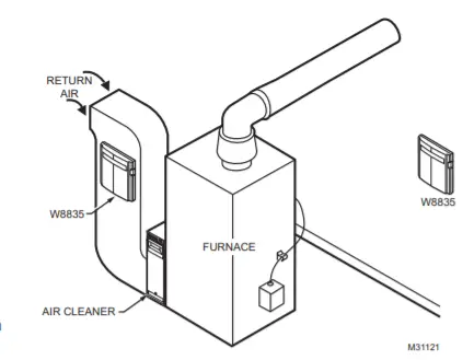
Fig. 4. Wiring single-stage heat pump with separate Auxiliary and Emergency Heat.
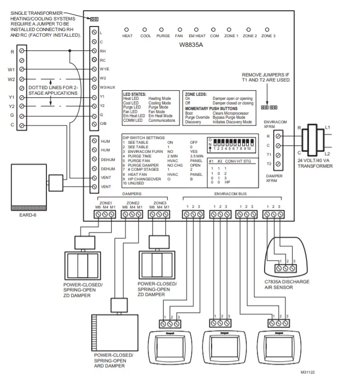
Fig. 5. Wiring single-stage heat pump with Auxiliary Heat.
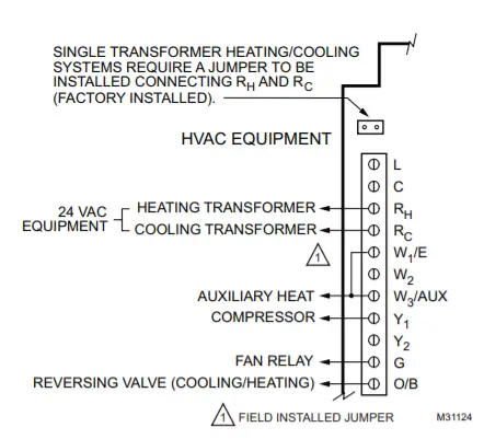
Fig. 6. Wiring two-stage heat pump with separate Auxiliary Heat.
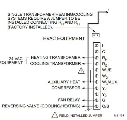
Fig. 7. Wiring two-stage heat pump with Auxiliary Heat.
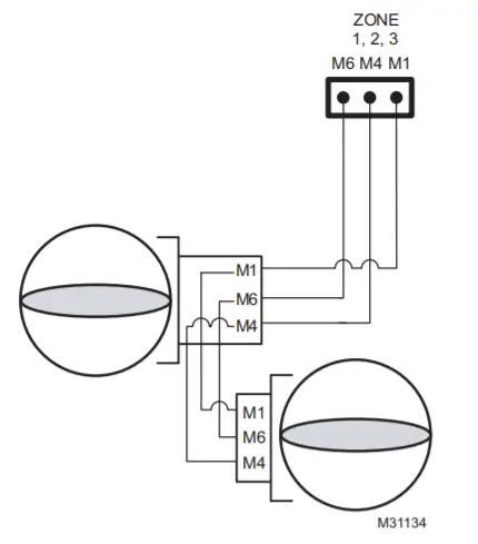
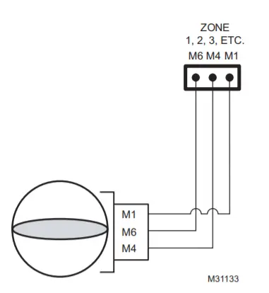
ARD or ZD Dampers
Wire the ARD or ZD Damper to the panel as shown in Fig. 8. Multiple dampers can be wired in parallel. Up to five ARD or ZD dampers can be connected in parallel to one zone. If five to ten dampers are connected to the panel an additional 40VA transformer must be connected to the panel.
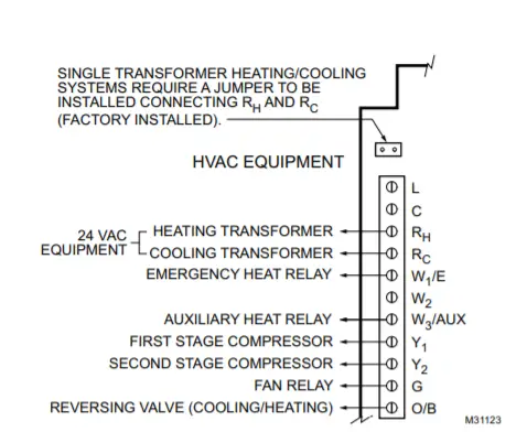
Fig. 8. Wiring ARD or ZD damper to panel.
RRD
Wire the RRD dampers to the panel as shown in Fig. 9. Two or more RRD can be wired in tandem as shown in Fig 10. Up to 12 RRD can be wired to one zone. Power the panel with one 40VA transformer if up to 12 dampers are connected to the panel. Power the panel with two 40VA transformers if up to 26 RRD are connected to the panel.
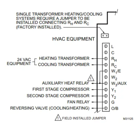
Fig. 9. Wiring RRD damper to panel.
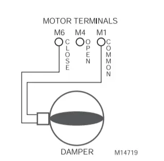
Fig. 10. Wiring two RRD dampers in parallel.
MARD Dampers or Dampers using ML6161 Motor Actuator
Wire the MARD Damper or other damper using the ML6161 Actuator to the panel as shown in Fig. 11. These floating control actuators are controlled as two-position devices on the W8835 panel. The ML6161 motor causes the damper LED to illuminate green constantly. To restore damper position indication, mount end switch 201052B onto the ML6161.
Transformer
Wire the transformers to the panel (see Fig. 12). One 40 VA, 24 Vac transformer is required to operate the panel and up to five ARD or ZD dampers. The transformer is connected to terminals R and C. The auxiliary transformer is required if up to ten dampers are connected to the panel. It is wired to terminals T1 and T2. If more than five ARD or ZD dampers are required for one zone of if more than ten ARD or ZD dampers are required for the W8835, use the Slave Damper Control Relay (SDCR). Locate the XFRM jumper shown in Fig. 12. These jumpers are shipped in the open, disconnected position. This is the correct position when two transformers are used. When using one transformer to power the panel, place the jumpers in the closed position. Do this by removing the jumpers and installing them so they cover both of their respective pins. If preferred, one 75 VA transformer may be used on this panel instead of two 40 VA. If this is done, leave the jumpers in the open, disconnected position and install a jumper between R and T1. Wire the transformer to R and C.
CAUTION
Equipment Damage Hazard. Incorrect transformer wiring can damage panel.
Wire transformers in phase when one transformer is wired to R and C and the auxiliary transformer is wired to T1 and T2.
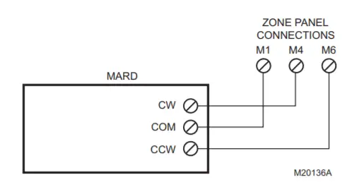
Fig. 12. Wiring transformer(s) to panel.
Wiring C7835 Discharge Air Temperature Sensor
Connect wire terminals 1, 2, and 3 to the corresponding terminals on either the W8835 EnviraZone panel or any other EnviraCom device such as a thermostat. Refer to C7835 Installation Instructions for configuration. Multiple devices can be wired in parallel to the each of the 1, 2, 3 terminals.
STARTUP AND CHECKOUT
- Verify that the equipment, thermostats, transformer, and Discharge Temperature Sensor are wired correctly. If one transformer is powering the panel, install the XFRM If two transformers are powering the panel, leave the XFRM jumper in the open position.
- Power up the W8835. Verify that all LEDs except COM illuminate for five The board should then enter the Purge mode with all dampers open. The damper LEDs are green to indicate the dampers are open. The COM LED begins to blink.
- Press the Purge Override button to terminate the Purge mode.
- On the W8835 Panel, set the DIP switches.
a. Set DIP switches 1, 2, and 7 to assign the appropriate number of heating and cooling stages. See Tables 5 and 6.
b. Configure other DIP switches, as necessary to fit the application. See Table 6. - On each thermostat, enter the Installer Setup procedures using the VisionPRO® IAQ Installation Instructions and assign each thermostat a zone number to correspond with its zone damper.
- Run Discovery by pressing the Discovery button on the
zone control panel. - On each thermostat, enter the Installer Setup procedures using the Installation Instructions and configure other pertinent Installer Setup options. Program the thermostat schedule if the default settings are not desired.
- Run Discovery by pressing the Discovery button on the panel.
- Set Zone one thermostat to heat and raise the setpoint to call for heat.
a. Verify that the heat LED is red
NOTE: The furnace heat may not come on immediately. Allow at least 5 minutes for heat to begin after the thermostat calls for heat.
b. Verify that Zone one LED remains green.
c. Verify that all other zone LEDs are not illuminated.
d. Change thermostat mode from Heat to Off. - Set Zone two thermostat to heat and raise the setpoint to call for heat.
a. Verify that the heat LED is red.
b. Verify that Zone two LED remains green.
c. Verify that all other zone LEDs are not illuminated.
d. Change thermostat mode from Heat to Off. - Alternatively, set a thermostat to Cool, lower the setpoint to call for cooling, wait five minutes, and verify correct operation.
OPERATION
Sequence of Operation
When there is no call for heat, cool or fan, the board is in the idle mode, indicated with no system LEDs illuminated, see Table 3. Damper LEDs are green to indicate open. On a call for heat, cool, or fan, the calling zone damper stays open and the damper LED remains illuminated; the other zone dampers close and corresponding damper LEDs do not illuminate.
The W8835 panel energizes the HVAC equipment and conditioned air is delivered to the calling zone. The heat LED (red), cool LED (green), or fan LED (green) illuminates to indicate equipment operation.
The fan LED illuminates only on a call for fan; it does not illuminate during a call for heat or cool. When the heat/cool call is satisfied, the system enters the Purge mode, indicated by the Purge LED (yellow). Damper positions either remain in the same positions as at the end of the call for heat or cool (default) or open, depending on the position of DIP switch 6. After purge, all dampers return to the Open position.
COM LED Operation
The green COM LED flickers as the W8835 communicates with the other EnviraCom devices:
LED blinks rapidly—indicates device is currently transmitting information on the communications bus.
LED blinks once—indicates device received and acknowledged a message.
LED on constantly— indicates panel failure. Replace panel.
LED off constantly—indicates a wiring problem.
Table 3. LED Indicatorsb
| LED | Color | Illuminated | Not Illuminated |
| Heat | Red | Heat call. | No heat calls. |
| Cool | Green | Cool call. | No cool calls. |
| Purge | Amber | Purge mode. | Not in Purge mode. |
| Fan | Green | Fan only call. | No fan only call. |
| Em Heat | Red | Emergency Heat mode. | Not in Emergency Heat mode. |
| Zone 1, 2, 3 | Green | Damper is open or opening. | Damper is closed or closing. |
b An LED change precedes the corresponding relay change by as much as six seconds.
Purge Mode
At the end of every call for heat or cool, the panel enters a Purge mode. DIP 4 configures the panel to purge for two (default) or three and one-half minutes. DIP switch 5 configures the panel or the HVAC equipment to operate the fan during purge. The Purge LED lights to signal that the system is in the Purge mode. Pressing the purge override button overrides the Purge mode. Unless there is a new call for heat or cool during the Purge mode, all dampers are moved to the Open position at the end of purge. DIP switch 6 is used if it desired to open all dampers during the Purge mode.
Table 4. Purge Configuration
| DIP Switch Number | Status | Purge |
| 4 | Off (Down) | 3.5 minutes purge |
| 4 | On (Up) | 2 minutes purge |
Table 5. Fan Control Configuration
| DIP Switch Number | Status | Fan Control |
| 5 | Off (Down) | Panel control of fan in Purge |
| 5 | On (Up) | HVAC control of fan in Purge |
Table 6. Purge Damper Configuration
| DIP Switch Number |
Status |
Purge Damper |
| 6 | On (Up) | Last zone(s) calling open during Purge |
| 6 | Off (Down) | Open all dampers during Purge |
Individual Zone Fan Control
When all zones are satisfied, the fan switch of each thermostat controls the fan operation for that zone. When the fan setting is “ On”, the fan is energized, the fan LED illuminates and the dampers close to zones where the fan setting is “Auto”. If there is a call for heat or cool during this time, the fan mode ceases, and the heat or cool call is honored. When the zone calling is satisfied, and Purge mode has ended, the fan call resumes.
Single and Multi-Stage Conventional Heat Operation
The panel can control up to three stages of heating and two stages of cooling based on thermostat demand. Set DIP switches 1 and 2 for 1, 2 or 3 stages of heat. Set DIP switch 7 for one or two stages of cooling.
Table 7. Conventional Equipment Configuration
| 1 Stage Cooling | ||
| Equipment Type | DIP 1 | DIP 2 |
| 1 Stage Conventional | On (Up) | On (Up) |
| 2 Stage Conventional | On (Up) | Off (Down) |
| 3 Stage Conventional | Off (Down) | On (Up) |
| 2 Stage Cooling | ||
| Cooling Stage | DIP7 | |
| 1 Stage | On (Up) | |
| 2 Stage | Off (Down) | |
Heat Pump Operation
The panel can control one or two compressor stages plus auxiliary heat. Set DIP switch 1 and 2 to Off; set DIP switch 7 to On for a single-stage compressor and to Off for a two-stage compressor.
Table 8. Heat Pump Equipment Configuration
| Equipment Type | DIP 1 | DIP 2 |
| Heat Pump | Off (Down) | Off (Down |
| Compressor Stages | DIP 7 | |
| 1 Stage | On (Up) | |
| 2 Stage | Off (Down | |
| Heat Pump Changeover | DIP 9 | |
| O (Cool) | On (Up) | |
| B (Heat) | Off (Down | |
Wire the reversing valve to the O/B equipment terminal. DIP switch 9 configures this terminal to operate as an O (cool) or B (heat) changeover terminal.
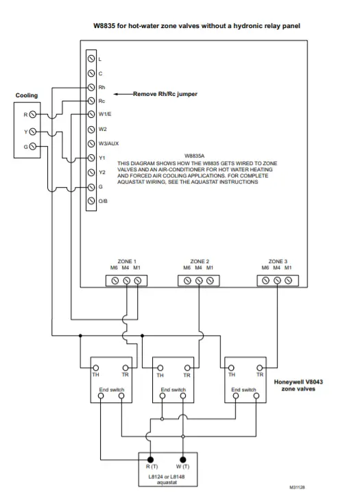
Hydronic Heat Operation
The W8835 is a forced air panel. However, it can be wired to control hydronic valves as shown in figure 13. To control valves or circulators on a hydronic panel, see figure 14.
Thermostat Operation
Dual Fuel Equipment
The W8835 can operate Dual fuel equipment when used with an external fossil fuel kit. Locate the thermostat on the fossil fuel kit instructions and wire the W8835 equipment terminals there.
Emergency Heat Control
Emergency heat is defined as using an auxiliary heat source without using the heat pump. The W8835 energizes the E terminal on a call for emergency heat. The thermostat system switch is set to Em Heat to engage this function. When active, any zone calling for heat uses Emergency Heat, not the compressor. The panel energizes W3 as auxiliary heat with the Y1 and Y2 for compressor control in when not in emergency heat.
Manual and Automatic Changeover Operation
Each of the thermostats can be set for manual or automatic changeover. If one or more thermostats call for cooling while one or more thermostats call for heating, the panel attempts to satisfy the greatest demand first. Then, based on the relative demand for heating and cooling, the panel intelligently switches between heating and cooling. The system attempts to satisfy both the heating and cooling demands, and does not lock out one demand in favor of the other.
Discovery
Discovery is an automatic system configuration program where the panel configures itself to operate with controls connected to the EnviraCom bus. The panel enters Discovery when the Discovery button on the panel is pressed.
Rebooting Microprocessor
To reset the microprocessor, press and release the Boot button. The system reboots and enters the Purge mode.
EnviraCom Furnace
For furnaces with EnviraCom communications built in, configure the panel as shown below. In this case, no conventional equipment wiring is necessary because the W8835 uses the 3-wire EnviraCom bus to control the HVAC equipment. In these installations, the panel is powered from the HVAC equipment via the 1, 2, 3 wires. Because of this, the transformer R and C terminals on the W8835 are not used. Instead, leave the XFMR jumpers in their default disconnected position and wire the transformer to T1 and T2.
Table 9. Furnace Type Configuration
| Type of Equipment | DIP 3 |
| Conventional | On (Up) |
| EnviraCom | Off (Down) |
Humidity, De-humidity and Ventilation Control
The panel can control humidity, de-humidity, and ventilation by receiving messages from the VisionPRO® IAQ thermostat. The thermostat designated as zone 1 will have control of these functions. Configure this thermostat as found in the installation instructions for the thermostat. The humidity, de-humidity, and ventilation terminals are all dry- contact terminals; the relay contacts close when active. So devices that need dry contact control like a ventilator can be wired directly to the VENT terminals, or a steam humidifier can be wired directly to the HUM terminals. Devices that need to be powered like a ventilation damper or some models of evaporative humidifiers are wired using the VENT or HUM terminals wired through the R terminal as shown in Fig. 3.
If using a Honeywell TrueSteam humidifier, configure the zone one VisionPRO IAQ thermostat installer setup #374 to “3”, and wire the TrueSteam GF terminal to the HVAC fan terminal, and wire the TrueSteam GT terminal to the G on the W8835.
NOTE: When controlling a steam humidifier, set all thermo- stats to HEAT. Do not set thermostats to AUTO. This prevents the panel from humidifying on zone 1, when another zone is calling for cooling. Alternatively, set zone 1 thermostat Installer Setup 374 to “2” to allow humidification only during calls for heat.
Discharge Air Temperature Sensor DATS
The C7835A1009 Discharge Air Temperature Sensor (included in the Y8835 kits) is a supply-duct-mounted temperature sensor probe used to control capacity and prevent high plenum temperatures or coil-icing. The sensor is wired to the EnviraCom bus using three wires. When a high or low limit is reached, the panel shuts off the equipment and keeps the fan operating for a minimum of two and one-half minutes. After this time, and any applicable minimum-off times imposed by the HVAC equipment. It re-energizes the equipment when the discharge air has recovered by ten degrees. When the high or low limit is exceeded, the Heat (red) or Cool (green) LED on the DATS flashes. When the DATS is in a limit condition, the Heat, Cool and Purge LEDs on the W8835 panel continue to operate as if the DATS were not turning the equipment off. The high and low limit is set on the DATS. The high temperature limit is set from 110°F to 160°F with a small screwdriver or using fingers and the low limit is set at 40°F or 48°F degrees with a jumper.
Circuit Breaker Protection
A built-in thermal circuit breaker protects the EnviraZone panel against shorts in the damper wiring and EnviraCom bus. It does not protect against shorts in the HVAC equipment wiring into the panel.
When the circuit breaker is tripped, none of the LEDs illuminate and the yellow rectangular component located bottom center on the panel is hot to touch.
- Remove power to the panel for at least five minutes to allow the circuit breaker to cool off and reset.
- To eliminate the short, verify the dampers and transformer wiring.
Fan On In Heat
The system blower can be set to come on with a call for heat as required for hydro-air or electric heat systems. Set the blower function using DIP switch 8. When configured for heat pump, this DIP switch is not used.
Table 10. Fan-in-heat Configuration
| DIP Switch 8 | Fan Control |
| Off (Down) | Fan on in heat by panel. |
| On (Up) | HVAC control of fan. |
Adding Additional Zones
Connect one W8703 to the EnviraCom bus to expand the system up to six zones or connect two W8703 to control up to nine zones:
- Wire the first three zone dampers and thermostats to the W8835 Envirazone Panel.
- Wire the additional dampers to the W8703 Panel.
- Set the DIP switches on the W8703 to correspond to the zones being See W8703 Installation Instructions.
- Wire terminals 1, 2, and 3 from the additional thermostats to terminals 1, 2, and 3 on any of the Panel.
TROUBLESHOOTING
Table 11. Troubleshooting
| Symptom | Possible Cause | Action |
| No LEDs are Illuminated. | No power to the board. | Check for 24 Vac (±10%) across R and C. |
| Transformers out of phase. | If 48 Vac across R and T1, reverse T1 and T2 wires. | |
| Shorted wire. | Check thermal circuit breaker. If hot, a short exists in wiring. | |
| Damper LEDs on, but no other LEDs illuminate on a call for heat, cool, or fan. | Insufficient voltage. | Check for 24 Vac (±10%) across R and C. |
| Incorrect configuration. | Check jumpers and DIP switches for correct configuration. | |
| Heat pump operates incorrectly or not at all. | Incorrect wiring. | Verify equipment terminals wiring. |
| Incorrect configuration. | Verify DIP switches configuration. | |
| No damper LEDs are illuminated. | Incorrect configuration. | Verify that XFRM jumpers are set correctly. |
| Error 35 or 39 message on thermostats. | Incorrect zone numbers. | Verify the thermostat zone numbers are set correctly (1,2,3 etc) |
| Wait is continuously in the thermostat display | Incorrect configuration | Verify dip switch 3 is set to conventional (Up) position. If controlling a heat pump, verify that thermostats are not configured to lockout the compressor based on outdoor temperature. (This feature is not used on zoned applications) |
Table 12. DIP Switches 1 and 2
| Equipment Type | DIP 1 | DIP2 |
| 1 Stage Conventional | On (up) | On (up) |
| 2 Stage Conventional | On (up) | Off (down) |
| 3 Stage conventional | Off (down) | On (up) |
| Heat Pump | Off (down) | Off (down) |
Table 13. DIP Switches 3–10
| DIP Switch | Function | On (Up, Default) | Off (Down) |
| 3 | Type of furnace | Conventional/non-communicating | EnviraCom Communicating |
| 4 | Purge time | Two minutes | 3.5 minutes |
| 5 | Fan control during purge | HVAC controlled | Panel controlled |
| 6 | Damper control during purge | Last zone(s) calling open during purge | Open all dampers during purge |
| 7 | Heat pump compressor stages | One stage | Two stages |
| 8 | Fan control in heat | Fan controlled by panel in cool and HVAC equipment in heat | Fan controlled by panel in heat and cool |
| 9 | Heat pump changeover | O (Cool changeover) | B (heat changeover) |
| 10 | Not used | — | — |
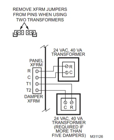
Fig. 13. Wiring reference, Zone Valve or Circulator Relay Panel
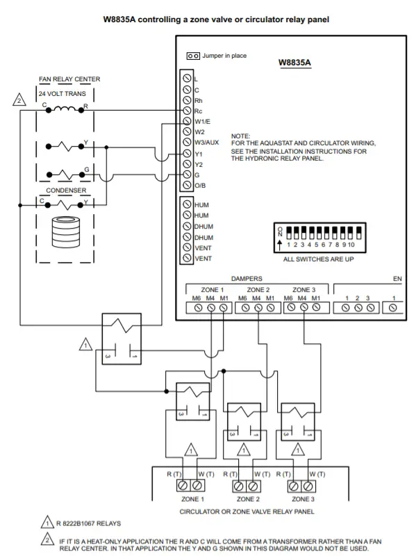
Fig. 14. Wiring Reference Hot Water Zone Valves
Automation and Control Solutions
Honeywell International Inc. Honeywell Limited-Honeywell Limitée
1985 Douglas Drive North 35 Dynamic Drive
Golden Valley, MN 55422 Toronto, Ontario M1V 4Z9
customer.honeywell.com
® U.S. Registered Trademark
© 2009 Honeywell International Inc.
68-0258—04 E.K. Rev. 08-09