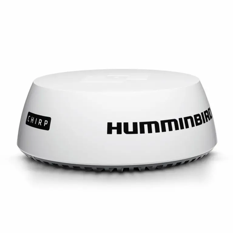
HUMMINBIRD CHIRP Radar Helix User Manual
IMPORTANT INFORMATION
 WARNING! Humminbird recommends certified installation by a Humminbird approved installer. Contact your Humminbird dealer for further details, and refer to the warranty information included with your product.
DANGER: MICROWAVE RADIATION HAZARD! The microwave energy radiated by a radar antenna is harmful to humans, especially to one’s eyes. Do NOT look at the scanner from close range. Never look directly into an open waveguide or into the path of radiation from an enclosed antenna. Make sure personnel are clear of the scanner when it is powered on. Turn off the radar whenever it is necessary to work on the antenna unit or on other equipment in the beam of the radar.
DANGER: MICROWAVE RADIATION HAZARD! Radar and other radio frequency radiation can upset cardiac pacemakers. If someone with a cardiac pacemaker suspects abnormal operation, immediately turn off the equipment and move the person away from the antenna.
HIGH VOLTAGE WARNING! Dangerously high voltages are present within the scanner unit. There are no internal connections or adjustments necessary for installation. Do NOT remove any covers or otherwise attempt to access internal components, unless specifically instructed in the documentation provided. The cover should be removed only by a qualified radar service technician. Technicians must exercise extreme care when working inside the unit.
WARNING! This product must be installed and operated in accordance with the instructions provided. Failure to do so could result in personal injury, damage to your vessel and/or poor product performance.
CAUTION! Installation and radar tuning should only be performed by a qualified radar service technician.
WARNING! How to interpret the radar display is not included in this manual. The captain is responsible for the proper use of radar and the safety of the vessel and its passengers.
WARNING! This device should not be used as a navigational aid to prevent collision, grounding, boat damage, or personal injury. When the boat is moving, water depth may change too quickly to allow time for you to react. Always operate the boat at very slow speeds if you suspect shallow water or submerged objects.
WARNING! The electronic chart in your Humminbird unit is an aid to navigation designed to facilitate the use of authorized government charts, not to replace them. Only official government charts and notices to mariners contain all of the current information needed for the safety of navigation, and the captain is responsible for their prudent use.
WARNING! Humminbird is not responsible for the loss of data files (waypoints, routes, tracks, groups, recordings, etc.) that may occur due to direct or indirect damage to the unit’s hardware or software. It is important to back up your control head’s data files periodically. Data files should also be saved to your PC before restoring the control head defaults or updating the software.
WARNING! Disassembly and repair of this electronic unit should only be performed by authorized service personnel. Any modification of the serial number or attempt to repair the original equipment or accessories by unauthorized individuals will void the warranty.
WARNING! This product contains chemicals known to the State of California to cause cancer and birth defects or other reproductive harm.
 NOTE: The illustrations in this manual may not look the same as your product, but your unit will function in a similar way.
NOTE: The procedures and features described in this manual are subject to change without notice. This manual was written in English and may have been translated to another language. Humminbird is not responsible for incorrect translations or discrepancies between documents.
NOTE: Product specifications and features are subject to change without notice.
NOTE: For installation information, see the installation manual included with your product.
NOTE: This product is specifically designed to be installed on
boats and other means of maritime transport. If your country forms part of the EU, please contact your dealer for advice before attempting to install elsewhere.
ROHS STATEMENT: Product designed and intended as a fixed installation or part of a system in a vessel may be considered beyond the scope of Directive 2002/95/EC of the European Parliament and of the Council of 27 January 2003 on the restriction of the use of certain hazardous substances in electrical and electronic equipment.
ENVIRONMENTAL COMPLIANCE STATEMENT: It is the intention of Johnson Outdoors Marine Electronics, Inc. to be a responsible corporate citizen, operating in compliance with known and applicable environmental regulations, and a good neighbor in the communities where we make or sell our products.
WEEE DIRECTIVE: EU Directive 2002/96/EC “Waste of Electrical and Electronic Equipment Directive (WEEE)” impacts most distributors, sellers, and manufacturers of consumer electronics in the European Union. The WEEE Directive requires the producer of consumer electronics to take responsibility for the management of waste from their products to achieve environmentally responsible disposal during the product life cycle.
WEEE compliance may not be required in your location for electrical & electronic equipment (EEE), nor may it be required for EEE designed and intended as fixed or temporary installation in transportation vehicles such as automobiles, aircraft, and boats. In some European Union member states, these vehicles are considered outside of the scope of the Directive, and EEE for those applications can be considered excluded from the WEEE Directive requirement.
![]() This symbol (WEEE wheelie bin) on product indicates the product must not be disposed of with other household refuse. It must be disposed of and collected for recycling and recovery of waste EEE. Johnson Outdoors Marine Electronics, Inc. will mark all EEE products in accordance with the WEEE Directive. It is our goal to comply in the collection, treatment, recovery, and environmentally sound disposal of those products; however, these requirements do vary within European Union member states. For more information about where you should dispose of your waste equipment for recycling and recovery and/or your European Union member state requirements, please contact your dealer or distributor from which your product was purchased.
This symbol (WEEE wheelie bin) on product indicates the product must not be disposed of with other household refuse. It must be disposed of and collected for recycling and recovery of waste EEE. Johnson Outdoors Marine Electronics, Inc. will mark all EEE products in accordance with the WEEE Directive. It is our goal to comply in the collection, treatment, recovery, and environmentally sound disposal of those products; however, these requirements do vary within European Union member states. For more information about where you should dispose of your waste equipment for recycling and recovery and/or your European Union member state requirements, please contact your dealer or distributor from which your product was purchased.
HELIX®, Humminbird®, and X-Press™ Menu are trademarked by or registered trademarks of Johnson Outdoors Marine Electronics, Inc. Adobe, Acrobat, Adobe PDF, and Reader are either registered trademarks or trademarks of Adobe Systems Incorporated in the United States and/or other countries. Baekmuk Batang, Baekmuk Dotum, Baekmuk Gulim, and Baekmuk Headline are registered trademarks owned by Kim Jeong-Hwan.
© 2017 Johnson Outdoors Marine Electronics, Inc. All rights reserved.
HOW CHIRP RADARWORKS
The word “radar” is an acronym for “Radio Detecting And Ranging.” A radio transmitter sends a quick microwave pulse, and then a receiver listens for that signal’s echo when it is bounced back from something in its path. The returning signal is processed by a computer to determine its relative distance, position, and bearing. This information is graphically displayed on a view for you to see. Other boats or ships, navigational markers, and landmasses are referred to as targets.
By knowing how long it takes for a signal to return, the distance to a target can be determined. As the radar antenna scans through a 360-degree rotation, it can show where the target is relative to your position. By repeated scans, you can see which direction another boat is moving. How a target is displayed on the screen depends on the target’s height and size as well as its material and
shape.
CHIRP Radar uses pulse compression technology, which sends continuous radar pulses to provide more detailed returns and better target separation.
CHIRP Radar provides:
- Improved range resolution and reduced sea clutter.
- Excellent short-range detection and enhanced target detail.
- Better separation quality.
![]() WARNING! How to interpret the radar display is not included in this manual. The captain is responsible for the proper use of radar and the safety of the vessel and its passengers.
WARNING! How to interpret the radar display is not included in this manual. The captain is responsible for the proper use of radar and the safety of the vessel and its passengers.
GETTING STARTED
The procedures in this section describe how to get started with your CHIRP Radar
Update the Control Head Software
It is important to install the latest software update (version 1.350 or later) on your control head to enable CHIRP Radar.
Compatibility: Visit our Web site at humminbird.com for the latest list of compatible models.
Required Equipment: Personal computer with Internet access, and a formatted SD card.
- Save Navigation Data: Before the control head software is updated or restored to system defaults, export your navigation data and copy your screen snapshots to an SD card. See your control head operations manual for instructions.
WARNING! Humminbird is not responsible for the loss of data files (waypoints, routes, tracks, groups, snapshots, recordings, etc.) that may occur due to direct or indirect damage to the unit’s hardware or software. It is important to back up your PC and control head data files periodically. See your control head operations manual for more information. - Install a blank SD card into the PC card slot.
- Go to humminbird.com, and select My Humminbird to sign in to your account.
- Select the My Equipment tab. The available software updates are listed as Downloads under each registered product.
• Under Downloads, click the file name.
• Read the instructions in the dialog box and select Download.
• Follow the on-screen prompts to save the software file to the SD card. - Repeat step 4 to download the software updates posted to each registered product.
- Power on your Humminbird control head. Start Normal mode.
- Insert the SD card (with the software file) into the control head card slot.
- Follow the on-screen prompts to update the control head software. See your control head operations manual for more details.
- When the software update is complete, remove the SD card from the control head card slot and restart the control head.
Power On the Control Head
Follow the instructions below to power on your Humminbird control head.
- Press the
 POWER key.
 - When the Title screen is displayed, press the MENU key.
- Start Normal mode.
OPEN RADAR VIEW
Use the instructions below to open Radar View. You can customize the Radar View by selecting which information to display or hide. See the section Customize the Radar Display Settings.
- Press the VIEW key until the Radar View is displayed.
OR
Press and hold the VIEW key. Select Radar > Radar View.

START/STOP RADAR TRANSMISSION
Use the instructions in this section to start transmission or start a timed transmission.
Start Transmission
- Power On: Turn on the radar power source (breaker or switch).
The radar will warm up for 60 to 90 seconds and then enter Standby mode. - Display a Radar View.
- When the Radar is ready to start transmission, a dialog box will display on-screen.
- Start Radar Transmission: Press the RIGHT Cursor key to select Transmission. Radar Transmission will start immediately.
![]()
Start Timed Transmission
Use Timed Transmission to set timed radar scans. This setting helps save power.
- Main Menu: Press the MENU key twice. Select the Accessories tab.
- Select Radar. Press the RIGHT Cursor key to open the menu.
- Select Timed Transmit. Select On.
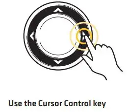
- Use the Cursor Control key to select settings from the menus shown below.
5. Close: Press the EXIT key repeatedly until the menu system is closed.
Stop Transmission
- Open the Radar X-Press Menu: With a Radar View displayed on the screen, press the MENU key.
- Select Radar.
- Press the LEFT Cursor key. A dialog box will display on screen.
- Press the LEFT Cursor key. Radar Transmission will stop, and the radar will enter Standy mode.
- Power Off: Turn off the radar power source from the breaker or switch.
 NOTE: The radar will continue to receive power until it is turned off at the power source (breaker or switch).
CONFIGURE THE RADAR SETTINGS
It is important to configure the radar settings before use on the water. Use the instructions in this section to set the Radar settings.
CAUTION! Installation and radar tuning should only be performed by a qualified radar service technician.
Select the Radar Mode
For optimum radar operation, select the radar mode for your current environment and weather. See the instructions below.
- Radar X-Press Menu: With a Radar View displayed on the screen, press the MENU key.
- Select Mode.
- Press the RIGHT or LEFT Cursor keys to select from the menus shown below.

Set the Transmission Range
The scanner transmission range can be adjusted from the X-Press Menu.
![]() NOTE: The range setting affects all the radar views in the control head. The control head will default to the largest chosen area from all the radar views.
NOTE: The range setting affects all the radar views in the control head. The control head will default to the largest chosen area from all the radar views.
Adjust the Range Using the X-Press Menu
- Radar X-Press Menu: With a Radar View displayed on the screen, press the MENU key.
- Select Range.
- Press the RIGHT or LEFT Cursor keys to adjust the setting.
![]() NOTE: To display the Range Rings, see Customize the Radar Display Settings: Display/ Hide Data in Radar View.
NOTE: To display the Range Rings, see Customize the Radar Display Settings: Display/ Hide Data in Radar View.

Adjust the Heading Line
Use the Adjust Heading Line setting to synchronize the on-screen heading with the actual boat heading so that north is displayed correctly on the view.
- Main Menu: Press the MENU key twice. Select the Accessories tab.
- Select Radar. Press the RIGHT Cursor key to open the menu.
- Select Adjust Heading Line.
- Adjust Heading Angle: Press the RIGHT or LEFT Cursor keys, and a gray line will display on the view. Use the cursor keys to set the angle of the heading line.
- Save: Press the CHECK/INFO key.


Set the Electronic Bearing Range (EBL) and Variable Range Ring (VRM)
Use EBL (Electronic Bearing Range) and VRM (Variable Range Ring) to measure the distance and bearing between any two targets on the Radar View.
The EBL and VRM can be set as a pair or individually. The marker is tied to the center of the boat. As the boat’s position and heading moves, the EBL/VRM also moves. The control head allows you to create two sets of EBL/VRM on the Radar View. You can choose to set the EBL/VRM with the cursor or by opening the X-Press Menu.
Create an EBL/VRM
Set the EBL/VRM individually or as a pair.
- Radar X-Press Menu: With a Radar View displayed on-screen, press the MENU key.
- Select Create EBL/VRM1 or Create EBL/VRM2 (for the second set).
- EBL: A dashed line will display on the Radar View. Press the RIGHT or LEFT Cursor keys to adjust the EBL.
- VRM: A dashed circle will display in the center of the Radar View. Press the UP or DOWN Cursor keys to adjust the VRM.
NOTE: To adjust the VRM without the EBL, skip step 3. To adjust the EBL without the VRM, skip step 4. - Press the ENTER/INFO key to save your settings.


Edit an EBL/VRM Pair
An EBL/VRM must be saved to access this menu option.
- With a Radar View displayed on-screen, press the MENU key.
- Choose Edit EBL/VRM from the X-Press Menu, and press the RIGHT Cursor key. If there is more than one EBL/VRM, use the Cursor Control key to select 1 or 2 from the submenu.
- EBL: Press the RIGHT or LEFT Cursor keys to adjust the EBL.
- VRM: Press the UP or DOWN Cursor keys to adjust the VRM.
 NOTE: To adjust the VRM without the EBL, skip step 3. To adjust the EBL without the VRM, skip step 4.
 - Press the CHECK/INFO key to save your settings.
Delete an EBL/VRM
An EBL/VRM must be saved to access this menu option.
- With a Radar View displayed on-screen, press the MENU key.
- Choose Delete EBL/VRM from the X-Press Menu, and press the RIGHT Cursor key.
If there is more than one EBL/VRM, use the Cursor Control key to select 1 or 2 from the submenu and press the RIGHT Cursor key.
CUSTOMIZE THE RADAR DISPLAY SETTINGS
Use the instructions in this section to set the Radar settings.
Adjust for Gain and Clutter
Use the settings in this section to filter the returns on the display or increase the amount of returns on the display.
Open the Settings Menu
- Radar X-Press Menu: With a Radar View displayed on the screen, press the MENU key.
- Select Settings. Press the RIGHT Cursor key to open the menu.
- Use the Cursor Control key to select settings from the menus shown below.

Adjust the Interference Rejection
Use the Interference Rejection setting to reduce the noise or interference from other transmitting radars in the area.
- Main Menu: Press the MENU key twice. Select the Accessories tab.
- Select Radar. Press the RIGHT Cursor key to open the menu.
- Select Interference Rejection.
- Press the RIGHT or LEFT Cursor keys to select the filter level.
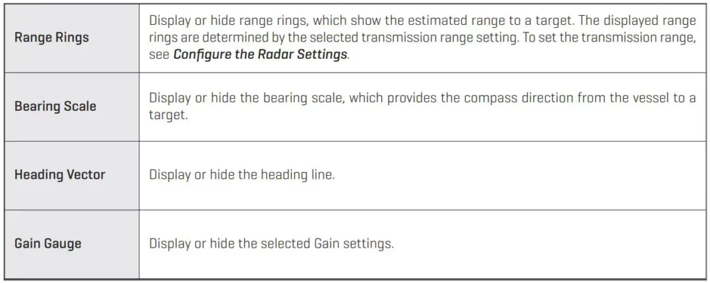
Display/Hide Data in Radar View
Use the instructions in this section to select how much data is displayed on the Radar View.
Open the Presentation Menu
- Radar X-Press Menu: With a Radar View displayed on the screen, press the MENU key.
- Select Presentation.
- Use the Cursor Control key to select On (visible) or Off (hidden) for the menus shown below.

Changing the Radar View Display Settings

Change the Radar View Color Palette
Use the Color Palette menu to select the palette used to display radar returns.
- Radar X-Press Menu: With a Radar View displayed on the screen, press the MENU key.
- Select Presentation. Press the RIGHT Cursor key to open the menu.
- Select Color Palette.
- Press the RIGHT or LEFT Cursor keys to choose a color palette. The colors in each palette are listed weakest return to strongest return.

NAVIGATION IN RADAR VIEW
You can mark waypoints and start navigation from the Radar View. See your control head operations manual for more information about navigation.
Mark a Waypoint
Mark a Waypoint at the Vessel Position
- Press the MARK key.
Mark a Waypoint at the Cursor Position
- Use the Cursor Control key to move the cursor to a position on the view.
- Press the MARK key.
Start Navigation
- Press the GO TO key.
- Select Nav Data. Press the RIGHT Cursor key.
- Use the Cursor Control key to select a saved route or waypoint. Press the RIGHT Cursor key to start navigation.
- Cancel Navigation: Press the MENU key once. Select Cancel Navigation, and press the RIGHT Cursor key.
CONTACT HUMMINBIRD
Contact Humminbird Customer Service in any of the following ways:
Web site:
humminbird.com
E-mail:
[email protected]
Telephone:
1-800-633-1468
Direct Shipping:
Humminbird
Service Department
678 Humminbird Lane
Eufaula, AL 36027 USA
Hours of Operation:
Monday – Friday
8:00 a.m. to 4:30 p.m. (Central Standard Time)
HUMMINBIRD Transom Transducer Installation Guide
![]()
The transom mount installation allows adjustment of both running angle and depth after the
transducer is mounted, which enables you to tune the installation for best results. It is important
to read the instructions completely and understand the mounting guidelines before beginning this installation.
![]() NOTE: Due to the wide variety of hulls, only general instructions are presented in this guide. Each boat hull represents a unique set of requirements that should be evaluated prior to installation. For detailed information about installing transducers on different hull types, download the Transducer Installation Resource Guide from our Web site at humminbird.com.
NOTE: Due to the wide variety of hulls, only general instructions are presented in this guide. Each boat hull represents a unique set of requirements that should be evaluated prior to installation. For detailed information about installing transducers on different hull types, download the Transducer Installation Resource Guide from our Web site at humminbird.com.
![]() NOTE: Your transducer may not look exactly like the transducer shown in the illustrations, but it will mount in exactly the same way.
NOTE: Your transducer may not look exactly like the transducer shown in the illustrations, but it will mount in exactly the same way.
Installation Preparation
Install the control head before you start the transducer installation. See the control head
installation guide.
Review your boat manufacturer’s owner’s manual for recommended transducer installation
locations and cable routing methods, as well as your transom and/or deadrise angle.
Read and understand your boat’s warranty before starting this installation.
Visit our Web site at humminbird.com for additional information and resources for transducer
installations. Also, visit youtube.com/humminbirdtv for informational videos.
Confirm your boat is level for the installation.
Consider your speed requirements.
Traveling over 65 mph with the transducer in the water is not recommended with the transom mount transducer, as damage may occur. If speed above 65 mph is critical, see the FAQ (Frequently Asked Questions) section of our Web site at humminbird.com.
Supplies: In addition to the hardware supplied with your transducer, you will need a powered
hand drill and various drill bits, various hand tools, including a ruler or straightedge, a level,
marker or pencil, Phillips-head screwdriver, flat head screw driver, a socket/nut driver, a 1/2″
(13 mm) wrench and torque wrench, safety glasses and dust mask, marine-grade silicone
sealant, and dielectric grease (optional). You may also need extension cables and hardware for
routing the cable to the control head.
Installation Overview
New Installation: Review Turbulence-Free Mounting Guidelines and proceed to section 1. Mount the Transom Bracket to the Boat.
Previously-installed Transducer: If you have a previously-installed XHS transducer on the transom, the bracket in this installation kit can be installed in the same location using the following instructions:
- Line up the metal bracket with the previously-used mounting holes to confirm that the two slot holes match the previous installation. Fill any unused holes with marine-grade silicone sealant.
- Make sure the boat is level on the trailer (from port to starboard and from bow to stern).
- Proceed to section 2. Install the Transducer.
Turbulence-Free Mounting Guidelines
It is very important to locate the transducer in an area that is relatively free of turbulent water.
Consider the following to find the best location with the least amount of turbulence:
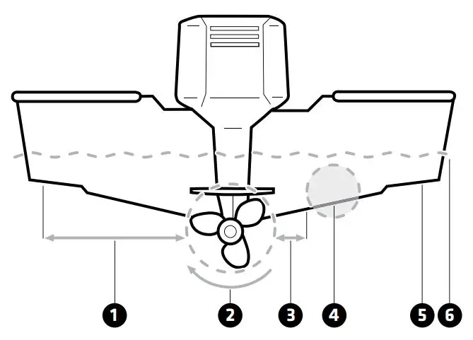
- Avoid areas where there is turbulent water flow. Turbulent water is normally confined to areas immediately aft of ribs, strakes, or rivets on the bottom of the boat, and in the immediate area of the propeller(s). The best way to locate turbulence-free water is to view the transom while the boat is moving.
- Observe your propeller’s direction of rotation (in forward, as you’re facing the stern of the boat from behind). Clockwise propellers create more turbulence on the port side. Counterclockwise propellers create more on the starboard side.
- Ensure there is adequate distance from the propeller(s). On outboard or inboard/outboard
boats, it is best to locate the transducer at least 15″ (38.1 cm) to the side of the propeller(s). - The ideal mounting location (right of the propeller[s]). It is important to note that if you plan to trailer your boat, do not mount the transducer too close to trailer bunks or rollers to avoid moving or damaging the transducer during loading and unloading of the boat.
- For boats with stepped hulls, it may be possible to mount the transducer on the step. Do not mount the transducer on the transom behind a step to avoid popping the transducer out of the water at higher speeds.
- The transducer must be mounted so that it is parallel with the waterline, but fully submerged in the water during operation.
- If you have a Side Imaging® transducer, the transducer must NOT have anything obstructing the ‘view’ of the side looking beams. For example, nothing can be in the line of sight of these beams (not a hull, motor, or other transducer, etc.)
![]() NOTE: You may need to tilt the motor up and out of the way when using the side looking beams.
NOTE: You may need to tilt the motor up and out of the way when using the side looking beams.
Deadrise: The hydrodynamic shape of your transducer allows the sonar beams to point down
without deadrise adjustment.
Unobstructed View: This jack plate installation gives the transducer safe distance from the motor and turbulence. The Side Imaging has a clear view side-to-side.
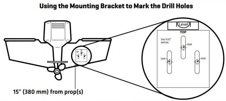
1 | Mount the Transom Bracket to the Boat
- Confirm the boat is level on the trailer (both from port to starboard and from bow to stern).
- Hold the mounting bracket against the transom of the boat in the location you have selected. Align the bracket horizontally, using the level. Make sure that the lower corner of the bracket does not protrude past the bottom of the hull.
If your propeller moves clockwise as the boat moves forward (as you’re facing the stern of
the boat from behind), mount the transducer on the starboard side. If your propeller moves
counterclockwise as the boat moves forward (as you’re facing the stern of the boat from
behind), mount the transducer on the port side.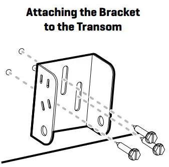
- Continue to hold the bracket on the transom of the boat, and use a pencil or marker to mark where to drill the three mounting holes. Mark the drill holes near the top of each slot, making sure that your mark is centered in the slot.
- Make sure the drill bit is perpendicular to the actual surface of the transom, NOT parallel to
the ground, before you drill.
Using a 5/32″ (4.0 mm) bit, drill the three holes to a depth of approximately 1″ (25 mm).
 NOTE: On fiberglass hulls, it is best to use progressively larger drill bits to reduce the chance of chipping or flaking the outer coating.
 - Use a marine-grade silicone sealant to fill the drilled holes.
- Align the transom bracket with the mounting holes. The center slot should be above the two outer slots. Confirm the bracket is level.
- Using a hand socket/nut driver, install the three #10-1″ (25 mm) screws into the drilled holes, but do not tighten completely.
NOTE: Make sure the mounting screws are snug, but do not fully tighten the mounting screws at this time to allow the transducer assembly to slide for adjustment purposes.
2 | Install the Transducer
The transom bracket allows you to adjust the height, and the pivot bolts allow you to adjust the
angle of the transducer. These adjustments help reduce cavitation and air bubbles around the
transducer during operation.
- Align the transducer bracket with the holes on top of the transducer.
- Use a Phillips-head screwdriver to install a 7/16″ (11 mm) screw and #8 split ring lock washer into each bracket hole (6 holes total). Hand tighten each screw until each split ring lock washer flattens. Hand tighten only.
- Align the holes on the transducer bracket with the holes on the transom bracket
![]()
4. Install the pivot bolt, 2 washers, and lock nut into the first hole as shown in the illustration
Installing the Transducer Bracket. Repeat for the second hole.
5. Use a 1/2″ (13 mm) wrench to tighten the assembly, but do not fully tighten the hardware at
this time (so you can make adjustments if needed after testing the installation).
![]()
![]()
3 | Confirm the Mounting Angle
You will need to adjust the initial angle of the transducer both vertically and horizontally to confirm the transducer mounting angle.
- Confirm the height of the transducer is high enough on the transom so it is out of the jet stream when the boat is on plane and that it will be submerged in the water during trolling speeds.
To adjust the height, loosen the screws slightly in the transom bracket, and slide the bracket up or down using the slots. If you cannot access the screws, you may need to uninstall the transducer, adjust the height, and repeat the installation instructions in sections 1 and 2. - Adjust the angle of the transducer, so it is parallel with the length of the boat hull, with a slight down angle (approximately 5 degrees).
![]()
3. Hand tighten the two pivot bolts, using a 1/2″ (13 mm) wrench.
![]() NOTE: You will finalize the installation after you route the cable and test the installation in
NOTE: You will finalize the installation after you route the cable and test the installation in
the following procedures.

4 | Route the Cable
You can route the cable over the transom or through a hole in the transom above the waterline.
Your boat may have a pre-existing wiring channel or conduit that you can use to route the cable.
Select the routing method that is best for your boat configuration, and purchase any extension
cables, cable clips, clamps, etc. as needed.
- It is best to route the cable to the side of the transducer so the transducer will not damage
the cable during movement. - The transducer can pivot up to 90 degrees in the bracket. Allow enough slack in the cable for this movement.
- If you drill any holes, fill them with marine-grade silicone sealant.
- Excess Cable: If there is excess cable that needs to be gathered at one location, dress the
cable routed from both directions so that a single loop is left extending from the storage
location. Doubling the cable up from this point, form the cable into a coil. Storing excess cable using this method can reduce electronic interference.
![]() CAUTION! Do not cut or shorten the transducer cable, and try not to damage the cable
CAUTION! Do not cut or shorten the transducer cable, and try not to damage the cable
insulation. Route the cable as far as possible from any VHF radio antenna cables or tachometer cables to reduce the possibility of interference. If the cable is too short, extension cables are available to extend the transducer cable up to a total of 50′. For assistance, contact Humminbird® Technical Support.
![]() CAUTION! Do NOT mount the cables where the connectors could be submerged in water or flooded. If cables are installed in a splash-prone area, it may be helpful to apply dielectric grease to the inside of the connectors to prevent corrosion. Dielectric grease can be
CAUTION! Do NOT mount the cables where the connectors could be submerged in water or flooded. If cables are installed in a splash-prone area, it may be helpful to apply dielectric grease to the inside of the connectors to prevent corrosion. Dielectric grease can be
purchased separately from a general hardware or automotive store.
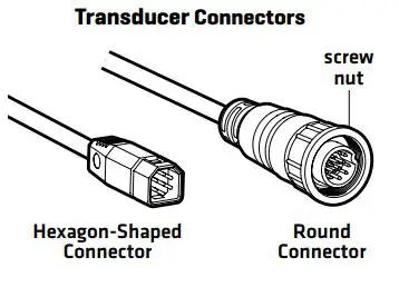
5 | Connect the Cable
Connect the transducer cable to the transducer port on the control head or cable connector
(if applicable).
The connector is keyed to prevent reversed installation, and insertion should be easy. Do not
force the connectors into the ports.
If the cable connector is round, hand-tighten the screw nut to secure the cable connection. Hand-tighten only!
Refer to your control head installation guide for additional details.
![]()
6 | Test and Finish the Installation
Once you have installed the control head, the transducer, and have routed all the cables, you must perform a final test before locking the transducer in place.
Testing should be performed with the boat in water deeper than 2 feet. The transducer should be fully submerged because the sonar signal cannot pass through air.
![]() WARNING! The transducer must be fully submerged in water during operation because the sonar signal cannot pass through air. Air pinging can damage the transducer.
WARNING! The transducer must be fully submerged in water during operation because the sonar signal cannot pass through air. Air pinging can damage the transducer.
Test the Transducer Installation on the Control Head
- Press the POWER key to turn on the control head.
If the transducer is detected, the control head will start Normal mode. - Select a Sonar View to display on-screen.
HELIX®: Press and hold the VIEW key. Select Sonar > Sonar View.
SOLIX®: Press the HOME key. Select a 2D Sonar View.
Other: See your control head operations manual. - If the bottom is visible on-screen with a digital depth readout, the unit is working properly.
- 2D Sonar Test: If the unit is working properly, gradually increase the boat speed to test highspeed performance.
- Review the sonar returns displayed on the (2D) Sonar View. If the unit functions well at low
speeds, but begins to skip or miss the bottom at higher speeds, the transducer requires
adjustment. CAUTION! If you do change the transducer position, re-trace the position of the mounting bracket before proceeding. - Side Imaging® Test: Select a Side Imaging View.
HELIX: Press and hold the VIEW key. Select Sonar > Side Imaging View.
SOLIX: Press the Home key. Select a Side Imaging View.
Other: See your control head operations manual. - Navigate the boat in a straight line at trolling speed. Confirm there is nothing obstructing the display of the side imaging beams.
Finalize the Transducer Installation
Once you have reached a consistently good sonar signal at the desired speeds, you are ready to lock down the transducer settings.
8. Confirm the transom bracket is level and hand tighten the screws until they are secure. Hand tighten only! Fully tighten the two pivot bolts, using a 1/2″ (13 mm) torque wrench to 12 ft-lbs. If you don’t have a torque wrench, use a crescent/box wrench to hand tighten the two pivot bolts until they are secure, then turn the wrench 45 to 60 degrees more. Hand tighten only!
Maintenance
If your transducer remains in the water for long periods of time, slush, algae and other marine growth can reduce the effectiveness of the transducer. Periodically clean the face of the transducer with a mild, marine-safe and plastic-safe soap or solution.
If your transducer remains out of the water for a long period of time, it may take some time to wet the transducer after it is returned to the water. Small air bubbles can cling to the surface of the transducer and interfere with proper operation. These bubbles will dissipate with time, or you may wipe the face of the transducer with your fingers after the transducer is in the water.
Contact Humminbird
Web site: humminbird.com
E-mail: [email protected]
Telephone: 1-800-633-1468
Direct Shipping: Humminbird
Service Department
678 Humminbird Lane
Eufaula, AL 36027 USA
![]() WARNING! Disassembly and repair of this electronic unit should only be performed by authorized service personnel. Any modification of the serial number or attempt to repair the original equipment or accessories by unauthorized individuals will void the warranty.
WARNING! Disassembly and repair of this electronic unit should only be performed by authorized service personnel. Any modification of the serial number or attempt to repair the original equipment or accessories by unauthorized individuals will void the warranty.
![]() WARNING! The transducer must be fully submerged in water during operation because the sonar signal cannot pass through air. Air pinging can damage the transducer.
WARNING! The transducer must be fully submerged in water during operation because the sonar signal cannot pass through air. Air pinging can damage the transducer.
![]() NOTE: Download Humminbird installation guides and operations manuals from our Web site at humminbird.com.
NOTE: Download Humminbird installation guides and operations manuals from our Web site at humminbird.com.
![]() NOTE: Product specifications and features are subject to change without notice.
NOTE: Product specifications and features are subject to change without notice.
ENVIRONMENTAL COMPLIANCE STATEMENT: It is the intention of Johnson Outdoors Marine Electronics, Inc. to be a responsible corporate citizen, operating in compliance with known and applicable environmental regulations, and a good neighbor in the communities where we make or sell our products.
WEEE DIRECTIVE: EU Directive 2002/96/EC “Waste of Electrical and Electronic Equipment Directive (WEEE)” impacts most distributors, sellers, and manufacturers of consumer electronics in the European Union. The WEEE Directive requires the producer of consumer electronics to take responsibility for the management of waste from their products to achieve environmentally responsible disposal during the product life cycle.
WEEE compliance may not be required in your location for electrical & electronic equipment (EEE), nor may it be required for EEE designed and intended as fixed or temporary installation in transportation vehicles such as automobiles, aircraft, and boats. In some European Union member states, these vehicles are considered outside of the scope of the Directive, and EEE for those applications can be considered excluded from the WEEE Directive requirement.
This symbol (WEEE wheelie bin) on product indicates the product must not be disposed of with other household refuse. It must be disposed of and collected for recycling and recovery of waste EEE. Johnson Outdoors Marine Electronics, Inc. will mark all EEE products in accordance with the WEEE Directive. It is our goal to comply in the collection, treatment, recovery, and environmentally sound disposal of those products; however, these requirements do vary within European Union member states. For more information about where you should dispose of your waste equipment for recycling and recovery and/or your European Union member state requirements, please contact your dealer or distributor from which your product was purchased.
© 2019 Johnson Outdoors Marine Electronics, Inc. All rights reserved.
]]>Quick Start Guide
Power On/Off

- Power On: Press the POWER key.
- Select the Stan-Up Mode: Press the MENU key on startup. Select Normal, and press the RIGHT Cursor key.
- Quick Setup: Use the Cursor Control key to select settings. Press the EXIT key to close the menu.
Power Off: Press and hold the POWER key.
Select Settings for Ice Fishing
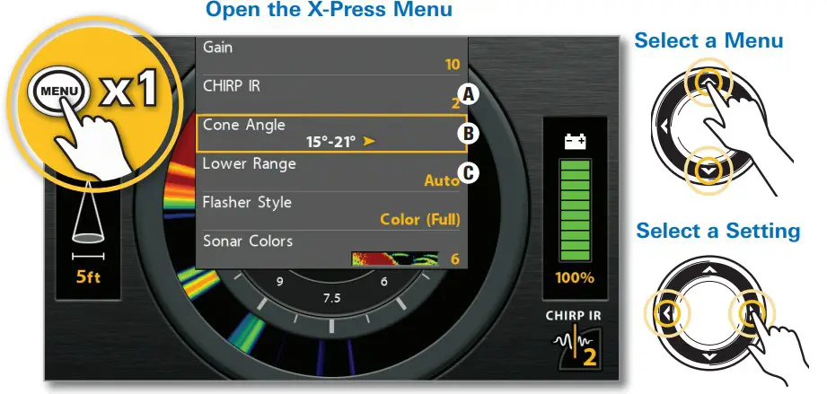
- Display a Sonar View: Press the VIEW key until a Sonar view is displayed.
- Open the X-PressTM Menu: Press the MENU key once.

A. CHIRP IR (Interference Rejection) (CHIRP models only) – If you are fishing near other ICE flashers or transducers, use CHIRP IR to reduce interference or noise on the sonar display.
B. Cone Angle (CHIRP models only) – Select 15° for a narrowly focused down the beam. Select 21° for a wide down beam and larger coverage area. Select 15°-21° to use the full frequency range for your transducer. CHIRP IR must be off to set the Cone Angle.
C. Lower Range – Use the default Auto depth range setting included with your control head, or manually set the depth range.
Display the Flasher View
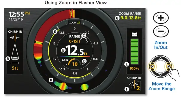
Flasher View provides two ways to view sonar data in traditional flasher format. Press the ZOOM In (+) key to magnify an area on the display.
Press the VIEW key until the Flasher View (shown below) is displayed.
A. Cone Angle shows the diameter of the sonar beam based on depth. This setting is affected by the CHIRP IR setting. See Select Settings for Ice Fishing.
B.Current Depth (;)
C. Current Depth Range and Lower Range Mode Indicator (Auto [A] or Manual [M].
D. Gain – Adjust the Gain setting from the X-Press Menu to see more or less detail on the sonar display. Decrease the setting to see less clutter. Increase the setting to see weaker returns in very clear and/or deep water.
E. Battery Status – The percentage of power remaining for the connected battery. To help extend battery life, reduce the screen’s backlight setting using the Power X-Press Menu (press the POWER key once) > Light.
F. CHIRP IR setting. See Select Settings for Ice Fishing.
G. Zoom Range
H. Flasher Window (Flasher Style set to Color [A-Scope]) displays the sonar returns. Select the Flasher Style from the X-Press Menu.
Display a 2D Sonar View
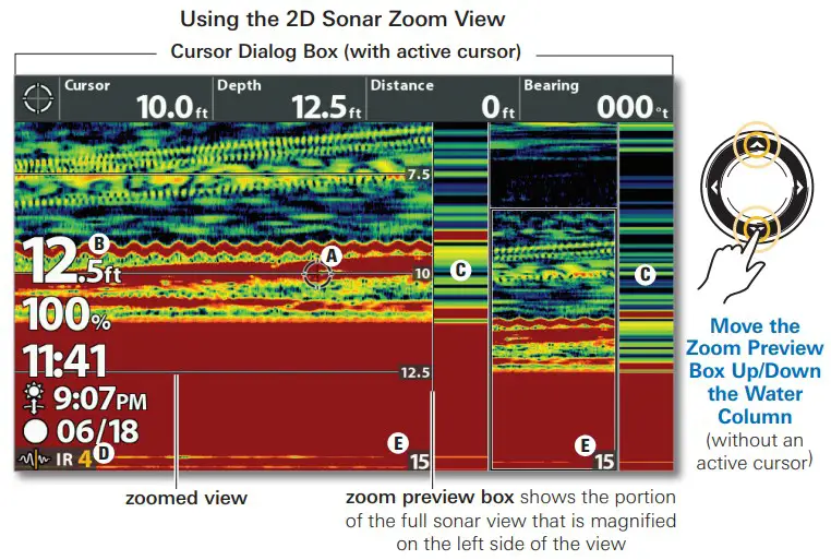
Your control head includes many different sonar views. Display the 2D Sonar Zoom View to see a magnified view of the bottom and structure.

A. Active Cursor will freeze the sonar history. To show the active cursor, turn on Show Cursor in the X-Press Menu. Use the Cursor Control key to move the cursor around the view. To remove the cursor, press the EXIT key.
B. Digital Readouts can be displayed as an overlay with fixed data readouts (shown above) or as data boxes, which can be customized.
C. Real-Time Sonar” (RTS) shows the depth and intensity of sonar returns for both the full sonar view and the zoomed view. With an active cursor, the sonar history will freeze, but the RTS Window will continue to display sonar returns in real-time. To select the display style (currently set to Color [A-Scope]) and width of the RTS Windows (or to turn off), use the X-Press Menu.
D.CHIRP IR setting. See Select Settings for Ice Fishing.
E.Lower Depth Range – See Select Settings for Ice Fishing.
Use Combo Views Combo
Views display two views (or more) on the screen at the same time. To change the settings, select menus or actions, or change the size of either view, you must select the view as the Active Pane from the X-Press Menu.
X-Press Menu > Active Pane

To quickly change display settings like Sonar Colors, Chart Speed, and Gain, use the X-Press Menu. To change advanced display settings like Units of Measure, Time and Date, adjust for Daylight Saving Time, display Digital Readouts, etc., use the Main Menu > Setup tab. Press the MENU key twice to open the Main Menu.
 NOTE: Some menu settings are only available in Advanced User Mode. bd To change the User Mode to Advanced, go to Main Menu > Setup tab > User Mode.
Download your Operations Manual
For additional instructions and information about your control head, download the operations manual from our Web site at humminbird.com.
NOTE: Your control head is compatible with other transducers and can be used on open water. To activate open water features, go to Main Menu > Sonar tab > Open Water. Mt
NOTE: Your control head is compatible with Humminbird LakeMaster maps. To purchase LakeMaster region maps, visit our Web site at humminbird.com. To purchase individual lake maps, visit https://chartselect.humminbird.com.
©2018 Johnson outdoors Marine Electronic, Inc. All Rights Reserved
]]>