HUMMINBIRD CHIRP Radar Helix User Manual
IMPORTANT INFORMATION
 WARNING! Humminbird recommends certified installation by a Humminbird approved installer. Contact your Humminbird dealer for further details, and refer to the warranty information included with your product.
DANGER: MICROWAVE RADIATION HAZARD! The microwave energy radiated by a radar antenna is harmful to humans, especially to one’s eyes. Do NOT look at the scanner from close range. Never look directly into an open waveguide or into the path of radiation from an enclosed antenna. Make sure personnel are clear of the scanner when it is powered on. Turn off the radar whenever it is necessary to work on the antenna unit or on other equipment in the beam of the radar.
DANGER: MICROWAVE RADIATION HAZARD! Radar and other radio frequency radiation can upset cardiac pacemakers. If someone with a cardiac pacemaker suspects abnormal operation, immediately turn off the equipment and move the person away from the antenna.
HIGH VOLTAGE WARNING! Dangerously high voltages are present within the scanner unit. There are no internal connections or adjustments necessary for installation. Do NOT remove any covers or otherwise attempt to access internal components, unless specifically instructed in the documentation provided. The cover should be removed only by a qualified radar service technician. Technicians must exercise extreme care when working inside the unit.
WARNING! This product must be installed and operated in accordance with the instructions provided. Failure to do so could result in personal injury, damage to your vessel and/or poor product performance.
CAUTION! Installation and radar tuning should only be performed by a qualified radar service technician.
WARNING! How to interpret the radar display is not included in this manual. The captain is responsible for the proper use of radar and the safety of the vessel and its passengers.
WARNING! This device should not be used as a navigational aid to prevent collision, grounding, boat damage, or personal injury. When the boat is moving, water depth may change too quickly to allow time for you to react. Always operate the boat at very slow speeds if you suspect shallow water or submerged objects.
WARNING! The electronic chart in your Humminbird unit is an aid to navigation designed to facilitate the use of authorized government charts, not to replace them. Only official government charts and notices to mariners contain all of the current information needed for the safety of navigation, and the captain is responsible for their prudent use.
WARNING! Humminbird is not responsible for the loss of data files (waypoints, routes, tracks, groups, recordings, etc.) that may occur due to direct or indirect damage to the unit’s hardware or software. It is important to back up your control head’s data files periodically. Data files should also be saved to your PC before restoring the control head defaults or updating the software.
WARNING! Disassembly and repair of this electronic unit should only be performed by authorized service personnel. Any modification of the serial number or attempt to repair the original equipment or accessories by unauthorized individuals will void the warranty.
WARNING! This product contains chemicals known to the State of California to cause cancer and birth defects or other reproductive harm.
 NOTE: The illustrations in this manual may not look the same as your product, but your unit will function in a similar way.
NOTE: The procedures and features described in this manual are subject to change without notice. This manual was written in English and may have been translated to another language. Humminbird is not responsible for incorrect translations or discrepancies between documents.
NOTE: Product specifications and features are subject to change without notice.
NOTE: For installation information, see the installation manual included with your product.
NOTE: This product is specifically designed to be installed on
boats and other means of maritime transport. If your country forms part of the EU, please contact your dealer for advice before attempting to install elsewhere.
ROHS STATEMENT: Product designed and intended as a fixed installation or part of a system in a vessel may be considered beyond the scope of Directive 2002/95/EC of the European Parliament and of the Council of 27 January 2003 on the restriction of the use of certain hazardous substances in electrical and electronic equipment.
ENVIRONMENTAL COMPLIANCE STATEMENT: It is the intention of Johnson Outdoors Marine Electronics, Inc. to be a responsible corporate citizen, operating in compliance with known and applicable environmental regulations, and a good neighbor in the communities where we make or sell our products.
WEEE DIRECTIVE: EU Directive 2002/96/EC “Waste of Electrical and Electronic Equipment Directive (WEEE)” impacts most distributors, sellers, and manufacturers of consumer electronics in the European Union. The WEEE Directive requires the producer of consumer electronics to take responsibility for the management of waste from their products to achieve environmentally responsible disposal during the product life cycle.
WEEE compliance may not be required in your location for electrical & electronic equipment (EEE), nor may it be required for EEE designed and intended as fixed or temporary installation in transportation vehicles such as automobiles, aircraft, and boats. In some European Union member states, these vehicles are considered outside of the scope of the Directive, and EEE for those applications can be considered excluded from the WEEE Directive requirement.
![]() This symbol (WEEE wheelie bin) on product indicates the product must not be disposed of with other household refuse. It must be disposed of and collected for recycling and recovery of waste EEE. Johnson Outdoors Marine Electronics, Inc. will mark all EEE products in accordance with the WEEE Directive. It is our goal to comply in the collection, treatment, recovery, and environmentally sound disposal of those products; however, these requirements do vary within European Union member states. For more information about where you should dispose of your waste equipment for recycling and recovery and/or your European Union member state requirements, please contact your dealer or distributor from which your product was purchased.
This symbol (WEEE wheelie bin) on product indicates the product must not be disposed of with other household refuse. It must be disposed of and collected for recycling and recovery of waste EEE. Johnson Outdoors Marine Electronics, Inc. will mark all EEE products in accordance with the WEEE Directive. It is our goal to comply in the collection, treatment, recovery, and environmentally sound disposal of those products; however, these requirements do vary within European Union member states. For more information about where you should dispose of your waste equipment for recycling and recovery and/or your European Union member state requirements, please contact your dealer or distributor from which your product was purchased.
HELIX®, Humminbird®, and X-Press™ Menu are trademarked by or registered trademarks of Johnson Outdoors Marine Electronics, Inc. Adobe, Acrobat, Adobe PDF, and Reader are either registered trademarks or trademarks of Adobe Systems Incorporated in the United States and/or other countries. Baekmuk Batang, Baekmuk Dotum, Baekmuk Gulim, and Baekmuk Headline are registered trademarks owned by Kim Jeong-Hwan.
© 2017 Johnson Outdoors Marine Electronics, Inc. All rights reserved.
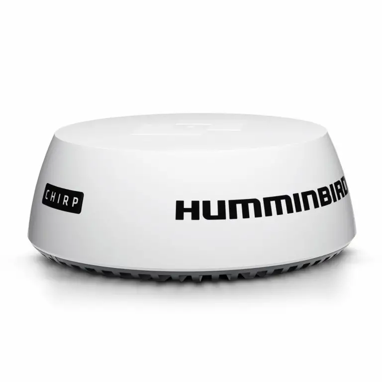
HOW CHIRP RADARWORKS
The word “radar” is an acronym for “Radio Detecting And Ranging.” A radio transmitter sends a quick microwave pulse, and then a receiver listens for that signal’s echo when it is bounced back from something in its path. The returning signal is processed by a computer to determine its relative distance, position, and bearing. This information is graphically displayed on a view for you to see. Other boats or ships, navigational markers, and landmasses are referred to as targets.
By knowing how long it takes for a signal to return, the distance to a target can be determined. As the radar antenna scans through a 360-degree rotation, it can show where the target is relative to your position. By repeated scans, you can see which direction another boat is moving. How a target is displayed on the screen depends on the target’s height and size as well as its material and
shape.
CHIRP Radar uses pulse compression technology, which sends continuous radar pulses to provide more detailed returns and better target separation.
CHIRP Radar provides:
- Improved range resolution and reduced sea clutter.
- Excellent short-range detection and enhanced target detail.
- Better separation quality.
![]() WARNING! How to interpret the radar display is not included in this manual. The captain is responsible for the proper use of radar and the safety of the vessel and its passengers.
WARNING! How to interpret the radar display is not included in this manual. The captain is responsible for the proper use of radar and the safety of the vessel and its passengers.
GETTING STARTED
The procedures in this section describe how to get started with your CHIRP Radar
Update the Control Head Software
It is important to install the latest software update (version 1.350 or later) on your control head to enable CHIRP Radar.
Compatibility: Visit our Web site at humminbird.com for the latest list of compatible models.
Required Equipment: Personal computer with Internet access, and a formatted SD card.
- Save Navigation Data: Before the control head software is updated or restored to system defaults, export your navigation data and copy your screen snapshots to an SD card. See your control head operations manual for instructions.
WARNING! Humminbird is not responsible for the loss of data files (waypoints, routes, tracks, groups, snapshots, recordings, etc.) that may occur due to direct or indirect damage to the unit’s hardware or software. It is important to back up your PC and control head data files periodically. See your control head operations manual for more information. - Install a blank SD card into the PC card slot.
- Go to humminbird.com, and select My Humminbird to sign in to your account.
- Select the My Equipment tab. The available software updates are listed as Downloads under each registered product.
• Under Downloads, click the file name.
• Read the instructions in the dialog box and select Download.
• Follow the on-screen prompts to save the software file to the SD card. - Repeat step 4 to download the software updates posted to each registered product.
- Power on your Humminbird control head. Start Normal mode.
- Insert the SD card (with the software file) into the control head card slot.
- Follow the on-screen prompts to update the control head software. See your control head operations manual for more details.
- When the software update is complete, remove the SD card from the control head card slot and restart the control head.
Power On the Control Head
Follow the instructions below to power on your Humminbird control head.
- Press the
 POWER key.
 - When the Title screen is displayed, press the MENU key.
- Start Normal mode.
OPEN RADAR VIEW
Use the instructions below to open Radar View. You can customize the Radar View by selecting which information to display or hide. See the section Customize the Radar Display Settings.
- Press the VIEW key until the Radar View is displayed.
OR
Press and hold the VIEW key. Select Radar > Radar View.

START/STOP RADAR TRANSMISSION
Use the instructions in this section to start transmission or start a timed transmission.
Start Transmission
- Power On: Turn on the radar power source (breaker or switch).
The radar will warm up for 60 to 90 seconds and then enter Standby mode. - Display a Radar View.
- When the Radar is ready to start transmission, a dialog box will display on-screen.
- Start Radar Transmission: Press the RIGHT Cursor key to select Transmission. Radar Transmission will start immediately.
![]()
Start Timed Transmission
Use Timed Transmission to set timed radar scans. This setting helps save power.
- Main Menu: Press the MENU key twice. Select the Accessories tab.
- Select Radar. Press the RIGHT Cursor key to open the menu.
- Select Timed Transmit. Select On.
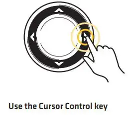
- Use the Cursor Control key to select settings from the menus shown below.
5. Close: Press the EXIT key repeatedly until the menu system is closed.
Stop Transmission
- Open the Radar X-Press Menu: With a Radar View displayed on the screen, press the MENU key.
- Select Radar.
- Press the LEFT Cursor key. A dialog box will display on screen.
- Press the LEFT Cursor key. Radar Transmission will stop, and the radar will enter Standy mode.
- Power Off: Turn off the radar power source from the breaker or switch.
 NOTE: The radar will continue to receive power until it is turned off at the power source (breaker or switch).
CONFIGURE THE RADAR SETTINGS
It is important to configure the radar settings before use on the water. Use the instructions in this section to set the Radar settings.
CAUTION! Installation and radar tuning should only be performed by a qualified radar service technician.
Select the Radar Mode
For optimum radar operation, select the radar mode for your current environment and weather. See the instructions below.
- Radar X-Press Menu: With a Radar View displayed on the screen, press the MENU key.
- Select Mode.
- Press the RIGHT or LEFT Cursor keys to select from the menus shown below.

Set the Transmission Range
The scanner transmission range can be adjusted from the X-Press Menu.
![]() NOTE: The range setting affects all the radar views in the control head. The control head will default to the largest chosen area from all the radar views.
NOTE: The range setting affects all the radar views in the control head. The control head will default to the largest chosen area from all the radar views.
Adjust the Range Using the X-Press Menu
- Radar X-Press Menu: With a Radar View displayed on the screen, press the MENU key.
- Select Range.
- Press the RIGHT or LEFT Cursor keys to adjust the setting.
![]() NOTE: To display the Range Rings, see Customize the Radar Display Settings: Display/ Hide Data in Radar View.
NOTE: To display the Range Rings, see Customize the Radar Display Settings: Display/ Hide Data in Radar View.

Adjust the Heading Line
Use the Adjust Heading Line setting to synchronize the on-screen heading with the actual boat heading so that north is displayed correctly on the view.
- Main Menu: Press the MENU key twice. Select the Accessories tab.
- Select Radar. Press the RIGHT Cursor key to open the menu.
- Select Adjust Heading Line.
- Adjust Heading Angle: Press the RIGHT or LEFT Cursor keys, and a gray line will display on the view. Use the cursor keys to set the angle of the heading line.
- Save: Press the CHECK/INFO key.


Set the Electronic Bearing Range (EBL) and Variable Range Ring (VRM)
Use EBL (Electronic Bearing Range) and VRM (Variable Range Ring) to measure the distance and bearing between any two targets on the Radar View.
The EBL and VRM can be set as a pair or individually. The marker is tied to the center of the boat. As the boat’s position and heading moves, the EBL/VRM also moves. The control head allows you to create two sets of EBL/VRM on the Radar View. You can choose to set the EBL/VRM with the cursor or by opening the X-Press Menu.
Create an EBL/VRM
Set the EBL/VRM individually or as a pair.
- Radar X-Press Menu: With a Radar View displayed on-screen, press the MENU key.
- Select Create EBL/VRM1 or Create EBL/VRM2 (for the second set).
- EBL: A dashed line will display on the Radar View. Press the RIGHT or LEFT Cursor keys to adjust the EBL.
- VRM: A dashed circle will display in the center of the Radar View. Press the UP or DOWN Cursor keys to adjust the VRM.
NOTE: To adjust the VRM without the EBL, skip step 3. To adjust the EBL without the VRM, skip step 4. - Press the ENTER/INFO key to save your settings.


Edit an EBL/VRM Pair
An EBL/VRM must be saved to access this menu option.
- With a Radar View displayed on-screen, press the MENU key.
- Choose Edit EBL/VRM from the X-Press Menu, and press the RIGHT Cursor key. If there is more than one EBL/VRM, use the Cursor Control key to select 1 or 2 from the submenu.
- EBL: Press the RIGHT or LEFT Cursor keys to adjust the EBL.
- VRM: Press the UP or DOWN Cursor keys to adjust the VRM.
 NOTE: To adjust the VRM without the EBL, skip step 3. To adjust the EBL without the VRM, skip step 4.
 - Press the CHECK/INFO key to save your settings.
Delete an EBL/VRM
An EBL/VRM must be saved to access this menu option.
- With a Radar View displayed on-screen, press the MENU key.
- Choose Delete EBL/VRM from the X-Press Menu, and press the RIGHT Cursor key.
If there is more than one EBL/VRM, use the Cursor Control key to select 1 or 2 from the submenu and press the RIGHT Cursor key.
CUSTOMIZE THE RADAR DISPLAY SETTINGS
Use the instructions in this section to set the Radar settings.
Adjust for Gain and Clutter
Use the settings in this section to filter the returns on the display or increase the amount of returns on the display.
Open the Settings Menu
- Radar X-Press Menu: With a Radar View displayed on the screen, press the MENU key.
- Select Settings. Press the RIGHT Cursor key to open the menu.
- Use the Cursor Control key to select settings from the menus shown below.

Adjust the Interference Rejection
Use the Interference Rejection setting to reduce the noise or interference from other transmitting radars in the area.
- Main Menu: Press the MENU key twice. Select the Accessories tab.
- Select Radar. Press the RIGHT Cursor key to open the menu.
- Select Interference Rejection.
- Press the RIGHT or LEFT Cursor keys to select the filter level.
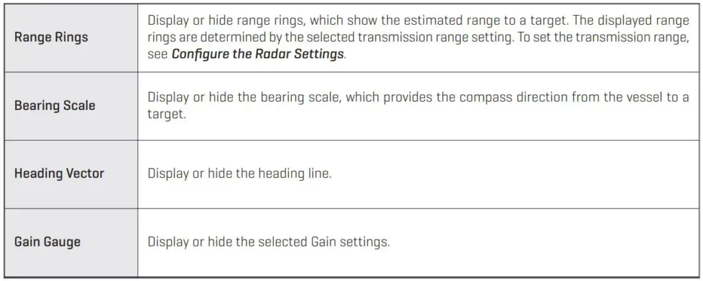
Display/Hide Data in Radar View
Use the instructions in this section to select how much data is displayed on the Radar View.
Open the Presentation Menu
- Radar X-Press Menu: With a Radar View displayed on the screen, press the MENU key.
- Select Presentation.
- Use the Cursor Control key to select On (visible) or Off (hidden) for the menus shown below.

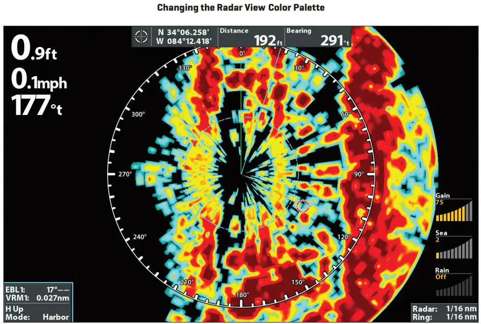
Changing the Radar View Display Settings

Change the Radar View Color Palette
Use the Color Palette menu to select the palette used to display radar returns.
- Radar X-Press Menu: With a Radar View displayed on the screen, press the MENU key.
- Select Presentation. Press the RIGHT Cursor key to open the menu.
- Select Color Palette.
- Press the RIGHT or LEFT Cursor keys to choose a color palette. The colors in each palette are listed weakest return to strongest return.

NAVIGATION IN RADAR VIEW
You can mark waypoints and start navigation from the Radar View. See your control head operations manual for more information about navigation.
Mark a Waypoint
Mark a Waypoint at the Vessel Position
- Press the MARK key.
Mark a Waypoint at the Cursor Position
- Use the Cursor Control key to move the cursor to a position on the view.
- Press the MARK key.
Start Navigation
- Press the GO TO key.
- Select Nav Data. Press the RIGHT Cursor key.
- Use the Cursor Control key to select a saved route or waypoint. Press the RIGHT Cursor key to start navigation.
- Cancel Navigation: Press the MENU key once. Select Cancel Navigation, and press the RIGHT Cursor key.
CONTACT HUMMINBIRD
Contact Humminbird Customer Service in any of the following ways:
Web site:
humminbird.com
E-mail:
[email protected]
Telephone:
1-800-633-1468
Direct Shipping:
Humminbird
Service Department
678 Humminbird Lane
Eufaula, AL 36027 USA
Hours of Operation:
Monday – Friday
8:00 a.m. to 4:30 p.m. (Central Standard Time)