
Safety Precautions
SAFETY FIRST!
To avoid personal injury, instrument damage and/or damage to your vehicle. This manual describes common test procedures used by experienced service technicians. Many test procedures require precautions to avoid accidents that can result in personal injury, and/or damage to your vehicle or test equipment. Always read your vehicle’s service manual and follow its safety precautions before and during any test or service procedure. ALWAYS observe the following general safety precautions:
- When an engine is running, it produces carbon monoxide, a toxic and poisonous gas. To prevent serious injury or death from carbon monoxide poisoning, operate the vehicle ONLY in a well-ventilated area.
- To protect your eyes from propelled objects as well as hot or caustic liquids, always wear approved safety eye protection.
- When an engine is running, many parts (such as the coolant fan, pulleys, fan belt etc.) turn at high speed. To avoid serious injury, always be aware of moving parts. Keep a safe distance from these
- parts as well as other potentially moving objects.
- Engine parts become very hot when the engine is running. To prevent severe burns, avoid contact with hot engine parts.
- Before starting an engine for testing or troubleshooting, make sure the parking brake is engaged. Put the transmission in park (for automatic transmission) or neutral (for manual transmission).
- Block the drive wheels with suitable blocks.
- Connecting or disconnecting test equipment when the ignition is ON can damage test equipment and the vehicle’s electronic components. Turn the ignition OFF before connecting the Code
- Reader to or disconnecting the Code Reader from the vehicle’s Data Link Connector (DLC).
- To prevent damage to the onboard computer when taking vehicle electrical measurements, always use a digital multimeter with at least 10 megOhms of impedance.
- Fuel and battery vapors are highly flammable. To prevent an explosion, keep all sparks, heated items and open flames away from the battery and fuel / fuel vapors. DO NOT SMOKE NEAR THE VEHICLE DURING TESTING.
- Don’t wear loose clothing or jewelry when working on an engine. Loose clothing can become caught in the fan, pulleys, belts, etc. Jewelry is highly conductive, and can cause a severe burn if it makes contact between a power source and the ground.
About the Code Reader
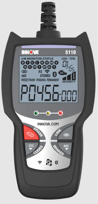
CONTROLS AND INDICATORS

Figure 1. Controls and Indicators
See Figure 1 for the locations of items 1 through 9, below.
- ERASE button – Erases Diagnostic Trouble Codes (DTCs) and “Freeze Frame” data from your vehicle’s computer, and resets Monitor status.
- DTC button – Displays the Diagnostic Trouble Codes View screen and/or scrolls the LCD display to view Diagnostic Trouble Codes.
- LINK button – When the Code Reader is connected to a vehicle, links the Code Reader to the vehicle’s PCM to retrieve Powertrain DTCs from the computer’s memory.
- ABS button – Links the Code Reader to the vehicle’s ABS control module to retrieve ABS DTCs from the computer’s memory.
- GREEN LED – Indicates that all engine systems are running normally (all Monitors on the vehicle are active and performing their diagnostic testing, and no DTCs are present).
- YELLOW LED – Indicates there is a possible problem. A “Pending” DTC is present and/or some of the vehicle’s emission monitors have not run their diagnostic testing.
- RED LED – Indicates there is a problem in one or more of the vehicle’s systems. The red LED is also used to show that DTC(s) are present. DTCs are shown on the Code Reader’s LCD display. In this case, the Malfunction Indicator (“Check Engine”) lamp on the vehicle’s instrument panel will light steady on.
- LCD Display – Displays test results, Code Reader functions and Moni-tor status information. See DISPLAY FUNCTIONS, below, for details.
- CABLE – Connects the Code Reader to the vehicle’s Data Link Connector (DLC).
DISPLAY FUNCTIONS

Figure 2. Display Functions
See Figure 2 for the locations of items 1 through 16 below.
- I/M MONITOR STATUS field – Identifies the I/M Monitor status area.
- Monitor icons – Indicate which Monitors are supported by the vehicle under test, and whether or not the associated Monitor has run its diagnostic testing (Monitor status). When a Monitor icon is solid, it indicates that the associated Monitor has completed its diagnostic testing. When a Monitor icon is flashing, it indicates that the vehicle supports the associated Monitor, but the Monitor has not yet run its diagnostic testing.The I/M Monitor Status icons are associated with INSPECTION and MAINTENANCE (I/M) READINESS STATUS. Some states require that all vehicle Monitors have run and completed their diagnostic testing before a vehicle can be tested for Emissions (Smog Check). A maximum of fifteen Monitors are used on OBD2 systems. Not all vehicles support all fifteen Monitors. When the Code Reader is linked to a vehicle, only the icons for Monitors that are supported by the vehicle under test are visible on the display.
- Link icon – Indicates whether or not the Code Reader is communicating (linked) with the vehicle’s on-board computers. When visible, the Code Reader is communicating with the computers. If the Link icon is not visible, the Code Reader is not communicating with the computers.
- Vehicle icon – Indicates whether or not the Code Reader is being properly powered through the vehicle’s Data Link Connector (DLC). A visible icon indicates that the Code Reader is being powered through the vehicle’s DLC connector.
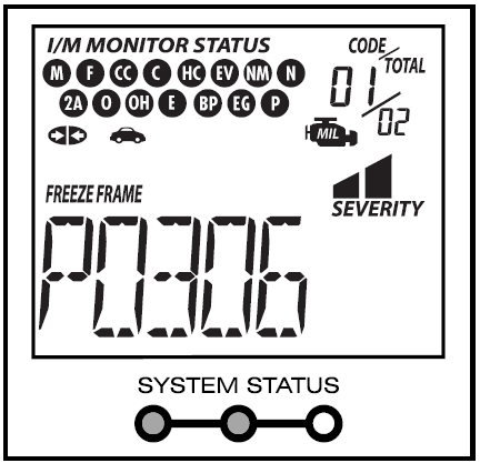
- MIL icon – Indicates the status of the Malfunction Indicator Lamp (MIL). The MIL icon is visible only when a DTC has commanded the MIL on the vehicle’s dashboard to light.
- ABS icon – Indicates the currently displayed DTC is an Anti-Lock Braking System code.
- HISTORY icon – Indicates the currently displayed DTC is a “History” code.
- FREEZE FRAME icon – Indicates that “Freeze Frame” data has been stored in the vehicle’s computer for the currently displayed DTC.
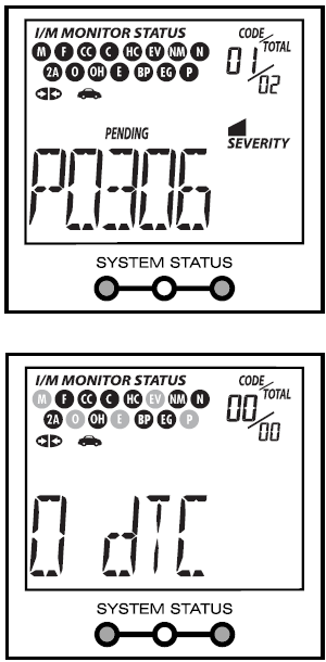
- PENDING icon – Indicates the currently displayed DTC is a “Pending” code.
- PERMANENT icon – Indicates the currently displayed DTC is a “Permanent” code.
- DTC Display Area – Displays the Diagnostic Trouble Code (DTC) number. Each fault is assigned a code number that is specific to that fault.
- Code Number Sequence – The Code Reader assigns a sequence number to each DTC that is present in the computer’s memory, starting with “01.” This helps keep track of the number of DTCs present in the computer’s memory. Code number “01” is always the highest priority code, and the one for which “Freeze Frame” data has been stored.
- Code Enumerator – Indicates the total number of codes retrieved from the vehicle’s computer.
- Severity – Indicates the level of severity for the priority code (code number “1”), as follows:
- Service should be scheduled and repairs made when convenient. This DTC typically has no immediate threat to essential system components in the short term.
- Repair immediately if drivability issues are present. Threat to essential system components if not repaired as soon as possible.
- Stop and repair vehicle immediately to prevent interrelated failures. Harmful and damaging to essential system components.
- Bluetooth icon – Indicates communication status with a compatible Innova mobile application (please visit www.innova.com/apps for more information). When ON, indicates an active Bluetooth connection has been established. When OFF, indicates Bluetooth is not connected.
- WiFi icon – Indicates WiFi communication status. When ON, indicates the scan tool is linked to a WiFi network. When OFF, indicates there is no WiFi connection.
Using the Code Reader
CODE RETRIEVAL PROCEDURE
Never replace a part based only on the DTC definition. Each DTC has a set of testing procedures, instructions and flow charts that must be followed to confirm the location of the problem. This information is found in the vehicle’s service manual. Always refer to the vehicle’s service manual for detailed testing instructions.
- Check your vehicle thoroughly before performing any test.
- ALWAYS observe safety precautions whenever working on a vehicle. See SAFETY FIRST! on page 1 for more information.
- Turn the ignition off.
- Locate the vehicle’s 16-pin Data Link Connector (DLC).
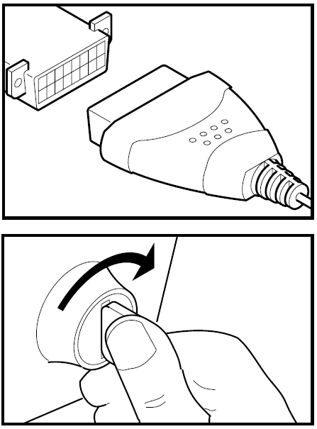
- Connect the Code Reader’s cable connector to the vehicle’s DLC. The cable connector is keyed and will only fit one way.
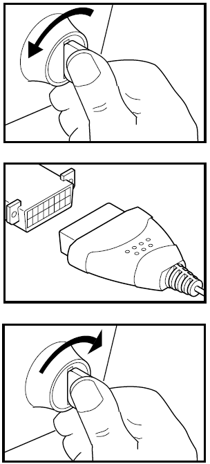
- If you have problems connecting the cable connector to the DLC, rotate the connector 180° and try again. If you still have problems, check the DLC on the vehicle and on the Code Reader. Refer to your vehicle’s service manual to properly check the vehicle’s DLC.
- After the Code Reader’s test connector is properly connected to the vehicle’s DLC, the Vehicle icon should display to confirm a good power connection.
- Turn the ignition on. DO NOT start the engine.
- The Code Reader will automatically link to the vehicle’s computer(s).
- If the LCD display is blank, it indicates there is no power at the vehicle’s DLC. Check your fuse panel and replace any burned-out fuses. If replacing the fuse(s) does not correct the problem, see your vehicle’s repair manual to locate the proper computer (PCM) fuse/circuit. Perform any necessary repairs before continuing.
- After 4-5 seconds, the Code Reader will retrieve and display any Diagnostic Trouble Codes that are in the vehicle’s computer memory.
- If Error is shown on the Code Reader’s LCD display, it indicates there is a communication problem. This means that the Code Reader is unable to communicate with the vehicle’s computer.
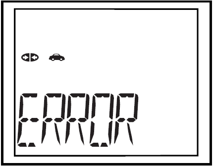
- Turn the ignition key off, wait 5 seconds and turn the key back on to reset the computer.
- Make sure your vehicle is OBD2 compliant.
- Read and interpret the Diagnostic Trouble Codes using the LCD display and the green, yellow and red LEDs.
- The green, yellow and red LEDs are used (with the LCD display) as visual aids to make it easier for the user to determine engine system conditions.
- Green LED – Indicates that all engine systems are “OK” and running normally. All monitors on the vehicle are active and are performing their diagnostic testing, and no trouble codes are present. The message 0 DTC will show on the Code Reader’s LCD display for further confirmation.
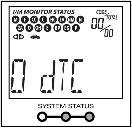
- Yellow LED – Indicates one of the following conditions: PENDING CODE PRESENT – If the yellow LED is lit, it may indicate the existence of a pending code. Check the Code Reader’s LCD display for confirmation. A pending code is confirmed by the presence of a numeric code and the word PENDING on the Code Reader’s LCD display. If no pending code is shown, the yellow LED indicates Monitor Status (see the following). MONITOR STATUS – If the Code Reader’s LCD display shows the message 0 DTC (indicating there are no DTCs present in the vehicle’s computer), but the yellow LED is lit, it indicates a “Monitor Has Not Run” status. This means that some of the Monitors on the vehicle have not yet finished their diagnostic self-testing. This condition is confirmed by one or more blinking Monitor icons on the LCD display. A blinking Monitor icon means the Monitor has not yet run and finished its diagnostic self-testing. All Monitor icons that are solid have completed their diagnostic self-testing.


Using the Code Reader
VIEWING ABS DTCs
- Red LED – Indicates there is a problem with one or more of the vehicle’s systems. The red LED is also used to show that DTC(s) are present (dis-played on the Code Reader’s LCD display). In this case, the Malfunction Indicator (Check Engine) lamp on the vehicle’s instrument panel will light steady on.
- The Code Reader will display a code only if codes are present in the vehicle’s computer memory. If no codes are present, a “0” will be displayed.

- If more than one code is present, press and release the DTC button, as necessary, to display additional codes.
- When the last retrieved DTC has been displayed and the DTC button is pressed, the Code Reader returns to the “Priority” code.Visit the manufacturer’s website for Fault Code Definitions. Match the retrieved DTC(s) with those listed. Read the associated definition(s), and see the vehicle’s service manual for further evaluation.
VIEWING ABS DTCs
ABS functionality is supported for Chrysler, Ford, GM, Honda, Hyundai, Kia, Mazda, Mitsubishi, Nissan, Subaru, and Toyota, vehicles (identified by VIN) only. Visit the manufacturer’s website for a complete list of vehicles covered.
- If not connected already, connect the Code Reader to the vehicle’s DLC, and turn the ignition “On.” (If the Code Reader is already connected and linked to the vehicle’s computer, proceed directly to step 3. If not, continue to step 2.)
- Perform the Code Retrieval procedure as described on page 7.
- Press the ABS button. After 4-5 seconds, the Code Reader will retrieve and display any Diagnostic Trouble Codes stored in the ABS controller’s memory.
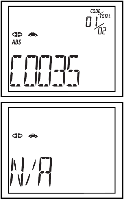
- If ABS functionality is not supported by your vehicle, the message “N/A” shows on the Code Reader’s display.
- The Code Reader will display a code only if codes are present in the vehicle’s computer memory. If no codes are present, the message 0 DTC will be displayed.
- If more than one code is present, press and release the ABS button, as necessary, to display additional codes.
- When the last retrieved DTC has been displayed and the ABS button is pressed, the Code Reader returns to the “Priority” code.
- To exit the ABS mode, press the DTC button to return to the OBD2 mode.

Visit the manufacturer’s website for Fault Code Definitions. Match the retrieved DTC(s) with those listed. Read the associated definition(s), and see the vehicle’s service manual for further evaluation.
ERASING DIAGNOSTIC TROUBLE CODES (DTCs)
When the Code Reader’s ERASE function is used to erase the DTCs from the vehicle’s on-board computer, “Freeze Frame” data and manufacturer-specific enhanced data are also erased. If you plan to take the vehicle to a Service Center for repair, DO NOT erase the codes from the vehicle’s computer. If the codes are erased, valuable information that might help the technician troubleshoot the problem will also be erased. Erase DTCs from the computer’s memory as follows: When DTCs are erased from the vehicle’s computer memory, the I/M Readiness Monitor Status program resets status of all the Monitors to a not run “flashing” condition. To set all of the Monitors to a DONE status, an OBD2 Drive Cycle must be performed. Refer to your vehicle’s service manual for information on how to perform an OBD2 Drive Cycle for the vehicle under test.
- If not connected already, connect the Code Reader to the vehicle’s DLC. (If the Code Reader is already connected and linked to the vehicle’s computer, proceed directly to step 4. If not, continue to step 2.)
- Turn the ignition on. DO NOT start the engine. The Code Reader will auto-matically link to the vehicle’s computer.
- To erase OBD2 DTCs: Wait until the codes are displayed on the Code Reader’s LCD and then proceed to step 3.
- To erase ABS DTCs: Press the ABS button to retrieve codes, and then proceed to step 3.
- Press and release the Code Reader’s ERASE button. The LCD display will indicate “ERASE?” for your confirmation.
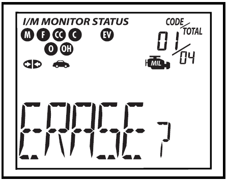
- If you change your mind and do not wish to erase the codes, press the DTC button to return to the code retrieval function.


ABOUT REPAIR SOLUTIONS
- If you wish to continue, press the ERASE button again. The message ERASE displays while the erase is in progress. When all retrievable information, including DTCs, has been cleared from the computer’s memory, the Code Reader will re-link to the vehicle’s computer, and the LCD display will show the message dONE.
- If the erase is not successful, the message SENT shows on the Coder Reader’s display.
- The Code Reader will relink to the previously selected module. Erasing DTCs does not fix the problem(s) that caused the code(s) to be set. If proper repairs to correct the problem that caused the code(s) to be set are not made, the code(s) will appear again (and the check engine light will illuminate) as soon as the vehicle is driven long enough for its Monitors to complete their testing.
ABOUT REPAIR SOLUTIONS 2
RepairSolutions 2® is a web-based service created to assist both Do-It-Yourself and Professional technicians in quickly and accurately diagnosing and repairing today’s vehicles. RepairSolutions 2 allows you to view and save the diagnostic data retrieved from a vehicle’s on-board computer(s) using your Code Reader. At the core of RepairSolutions 2 is an extensive knowledge database, developed by compiling and analyzing years worth of “real world” vehicle service data. RepairSolutions 2 builds on manufacturer-recommended diagnostic and repair information by providing verified, vehicle-specific fixes supplied by ASE technicians across the country. RepairSolutions 2 also provides access to an extensive knowledge database including:
- Verified Fixes – Find the most likely fixes reported and verified by ASE Technicians for the retrieved DTCs.
- Repair Instructions – View available repair instructions to properly perform the fix.
- Video Tutorials – Watch repair video tutorials for valuable repair tips.
- Technical Service Bulletins – Research known problems reported by vehicle manufacturers.
- Safety Recalls – Research known safety concerns applicable to a vehicle.
And much more. Please visit www.innova.com for additional information. Hardware Requirements:
- Innova Code Reader with Bluetooth/WiFi
- Android or iOS Smart Device
Accessing RepairSolutions 2
- Download and install the RepairSolutions 2® app from the App Store (for iOS devices) or Google Play (for Android devices).
- Launch the RepairSolutions 2 app and log in to your account.
- If you have not yet established an account, you must register for a FREE RepairSolutions 2 account before proceeding.
- Connect the Code Reader to a vehicle and establish a Bluetooth or WiFi connection with your Smart Device (refer to CONNECTING TO BLUETOOTH / WIFI, below). Be sure your Smart Device is connected to an available WiFi network.
- The RepairSolutions 2 app will store three WiFi configurations only.
- Retrieve diagnostic data (refer to CODE RETRIEVAL PROCEDURE on 7 for details).
- The RepairSolutions 2 app automatically displays a report based on the retrieved diagnostic data.
- If the Code Reader is not connected to WiFi or Bluetooth, vehicle data will not be saved.
CONNECTING TO BLUETOOTH / WIFI
Launch the RepairSolutions 2 app and follow the prompts to establish Bluetooth and (optionally) WiFi connections, as follows:
- Launch the RepairSolutions 2 app. Select Wifi Tools Settings from the menu. Power on your Code Reader, then select from the list of available devices.
- When Bluetooth pairing is complete, a confirmation screen displays. Click Continue.
- If a Bluetooth connection cannot be established, an advisory message displays. Tap Try Again to repeat the pairing process.
- Follow the on-screen prompts to connect to an available WiFi network.
- You can automatically connect to the network your Smart Device is currently connected to, or you can manually connect to another available network.
- Note that only 2.4GHz networks are supported.
- If you do not wish to connect to a WiFi network at this time, tap SKIP.
- When WiFi pairing is complete, a confirmation screen displays. Click Continue to view the “Setup Complete” message, then click Continue to enter RepairSolutions 2.
- If a WiFi connection cannot be established, an advisory message displays. Tap Try Again to repeat the pairing process.
Warranty and Servicing
LIMITED ONE-YEAR WARRANTY
The Manufacturer warrants to the original purchaser that this unit is free of defects in materials and workmanship under normal use and maintenance for a period of one (1) year from the date of original purchase. If the unit fails within the one (1) year period, it will be repaired or replaced, at the Manufacturer’s option, at no charge, when returned prepaid to the Service Center with Proof of Purchase. The sales receipt may be used for this purpose. Installation labor is not covered under this warranty. All replacement parts, whether new or remanufactured, assume as their warranty period only the remaining time of this warranty. This warranty does not apply to damage caused by improper use, accident, abuse, improper voltage, service, fire, flood, lightning, or other acts of God, or if the product was altered or repaired by anyone other than the Manufacturer’s Service Center. The Manufacturer, under no circumstances, shall be liable for any consequential damages for breach of any written warranty of this unit. This warranty gives you specific legal rights, and you may also have rights, which vary from state to state. This manual is copyrighted with all rights reserved. No portion of this document may be copied or reproduced by any means without the express written permission of the Manufacturer. THIS WARRANTY IS NOT TRANSFERABLE. For service, send via U.P.S. (if possible) prepaid to the Manufacturer. Allow 3-4 weeks for service/repair.
SERVICE PROCEDURES
If you have any questions or require technical support or information on UPDATES and OPTIONAL ACCESSORIES, please contact your local store, distributor or the Service Center.
USA & Canada:
(800) 544-4124 (6:00 AM-6:00 PM PST, Monday through Saturday)
All others: (714) 241-6802 (6:00 AM-6:00 PM PST, Monday through Saturday)
- FAX: (714) 241-3979 (24 hr.)
- Web: www.innova.com
INN(o)VA Innova Electronics Corp. 17352 Von Karman Ave. Irvine, CA 92614 Copyright© 2019 IEC. All Rights Reserved.