
Intelliflo VS-3050 Pump Manual
(Compatible with IntelliComm® communication center and
EasyTouch®, IntelliTouch® and SunTouch® control systems)
Installation and User’s Guide
Pump Overview
Introduction
The IntelliFlo® Variable Speed pump is well suited for all of your pool, spa, cleaner, waterfall and other water applications. Using the control panel, IntelliFlo® can use one of the four selectable preset speeds or the pump speed can be adjusted to run at a speci c speed. Advanced energy conservation features ensure that your ltration system is operating at peak ef ciency.
The IntelliFlo® pump is a variable speed pump that can use up to eight speeds that can be adjusted to run at speci c speeds and time intervals. The IntelliFlo® Variable Speed pump out performs all conventional pumps in its class.
The pump can operate from 450 RPM to 3450 RPM with preset speeds of 750, 1500, 2350 and 3110 RPM. The pump can be adjusted from the control panel to run at any speed between 450 RPM to 3450 RPM for different applications. The pump control panel alarm LED and error messages warn the user against under and over voltage, high temperature, over current and freeze protection with user de ned minimum and maximum speed presets.
External Control
The IntelliFlo® pump can communicate with an IntelliTouch®, EasyTouch®, or SunTouch® control system or the IntelliComm® communication center via a two-wire RS-485 communication cable.The communication cable is included with the IntelliFlo® Variable Speed pump. EasyTouch® and IntelliComm® can remotely control the IntelliFlo® Variable speed four preset speeds. The IntelliTouch® system can be con gured to control a total of eight speeds. The pump’s address and other pump functions are accessed from the pump’s control panel.
IntelliFlo® Variable Speed Pump
Features
??Adjusts to various pool sizes
??Prevents thermal overload
??Detects and prevents damage from under and over voltage conditions
??Protects against freezing
??Communicates with EasyTouch, IntelliTouch or SunTouch control systems or an IntelliComm communication center via a two-wire RS-485 cable connection
??Easy to use operator control panel
??Operator control panel buttons for speed control
??Built-in strainer pot and volute
??Ultra energy-ef cient TEFC Square Flange Motor
??Compatible with most cleaning systems, lters, and jet action spas
??Motor assembly features permanent magnet synchronous motor
??Heavy-duty, durable construction designed for long life
??12 Programmable Speeds
? ??Eight Set speeds
? ??Schedule
? ??Duration
? ??Manual
? ??Four IntelliComm speed modes
??Priming Feature
? ??Load Sensing
? ??Enable or Disable
??Lock out protection
? ??Four Digit password
? ??Enable or Disable
??LCD Display
? ??Power and Speed
? ??Text Alerts
??Antifreeze Protection
? ??Adjustable speed
? ??Adjustable Temperatures
? ??Enable and Disable in stand alone
??Additional Features
? ??Clock and Timer
? ?? Maximum and Minimum Speed Limits
?? Quick Clean Mode
? ??Address up to 16 pumps
? ??Service Features
? ??Timeout Mode
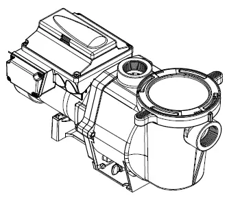
IntelliFlo® Drive Assembly and Control Panel
The IntelliFlo® drive assembly consists of an operator control panel and the system electronics that drive the motor. The drive microprocessor controls the motor by changing the frequency of the current it receives together, with changing the voltage to control the rotational speed.
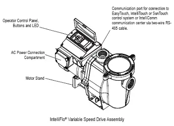
IntelliFlo® Variable Speed Drive Assembly
IntelliFlo® Variable Speed Motor Features
• Permanent Magnet Synchronous Motor (PMSM)
• High ef ciency (3450 RPM 92% and 1000 RPM 90%)
• Superior speed control
• Operates at lower temperatures due to high ef ciency
• Same technology as deployed in hybrid electric vehicles
• Designed to withstand outdoor environment
• Totally enclosed fan cooled
• Three-phase motor
• 56 Square Flange
• Six-Pole
• Low noise
Operator Control Panel
This section describes the IntelliFlo® Variable Speed pump operator controls and LEDs.
IntelliFlo® Operator Control Panel
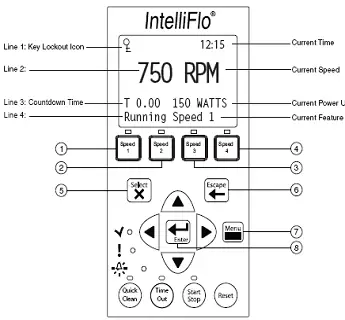
Controls and LEDs
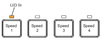
1. Speed 1 button/LED: Press button to select Speed 1 (750 RPM). LED on indicates Speed 1 is active.
2. Speed 2 button/LED: Press button to select Speed 2 (1500 RPM). LED on indicates Speed 2 is active.
3. Speed 3 button/LED: Press button to select Speed 3 (2350 RPM). LED on indicates Speed 3 is active.
4. Speed 4 button/LED: Press button to select Speed 4 (3110 RPM). LED on indicates Speed 4 is active.
5. Select button: Displays available menu items or enters edit mode for changing a value on line two of the display.
6. Escape button: Moves to next level up in the menu structure, and/or stops editing the current setting.
7. Menu button: Accesses the menu items if the pump is stopped.
8.Enter button: Saves current menu item setting. Press this button to acknowledge alarms and warning alerts.
9. Arrow buttons:
• Up arrow: Move one level up in the menu tree or increase a digit when editing a setting.
• Down arrow: Move one level down in the menu tree or decrease a digit when editing a setting.
• Left arrow: Move cursor left one digit when editing a setting.
• Right arrow: Move cursor right one digit when editing a setting.
10. Quick Clean: Duration and speed (RPM) can be preset to save energy. The LED is on when active.
11. Time Out: When active (LED on), at the end of a “Time Out” preset time, the pump will run a schedule.
12.Start/Stop button: Start or Stop the pump. When the LED is on, the pump is currently running or in a mode to start automatically.
13. Reset button: Reset alarm or alert.
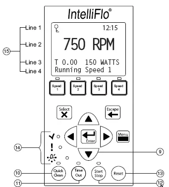
14.LEDs
On: This green, power LED is on when IntelliFlo® is powered on.
Warning: LED is on if a warning condition is present.
Alarm: The red LED is on if an alarm condition occurs. See “Alerts and Warnings” on page 35.
15. Control Panel LCD:
• Line 1 – Key icon indicates password protect mode is active. If password protect is not enabled, no key icon is displayed.
• Line 2 – Displays the current pump speed (RPM).
• Line 3 – Count down time and Watts
• Line 4 – Current pump status.
Operating the Pump
This section describes how to operate the IntelliFlo® pump using the control panel buttons and menu features.
Starting the pump
To start the pump
1. Be sure the pump is powered on and the green power LED is on.
2. Select one of the speed buttons, then press the Start button (LED on) to start the pump.
Stopping the pump
To stop the pump
• Press the Stop button to stop the pump.
Note: The pump can automatically restart if the communication cable is connected.
Servicing Equipment (Disconnect Power to Pump)
• When servicing equipment ( lters, heaters, chlorinators etc.), disconnect the communication cable, and switch OFF circuit breaker to remove power from the pump.
Operating the IntelliFlo Pump at Preset Speeds
The IntelliFlo® Variable Speed pump is programmed with four default speeds of 750, 1500, 2350 and 3110 RPM. A Speed button is assigned to each of the preset speeds as shown.
To operate the pump at one of the four preset speeds
1. Be sure the pump is powered on and the green power LED is on.
2. Press the Speed button (1- 4) corresponding to the desired preset speed, and release quickly. The LED above the Speed button will come on as shown.
3. Press the Start button. The pump will quickly ramp to the selected preset speed.
Adjusting the pump speed
1. While the pump is running, press the Up Arrow to increase speed setting.
2. Press the Down Arrow to decrease speed Setting.
3. Press and hold down a Speed Button for three (3) seconds to save speed to the button or press the Enter button to save the speed.
Pump Operating Modes
The IntelliFlo® Variable Speed pump can be programmed three ways:
1. Manual Operation: Speed buttons 1-4 can be programmed for Manual operation. This means the speed button is pressed and then the start button and the pump runs a programmed speed. Speeds 5-8 cannot be programmed for Manual operation because there are no buttons associated with them.
To operate the pump in Manual Mode, press one of the four speed buttons, and press the Start/Stop button to run the assigned speed for that button. When the pump is running a Manual Speed Setting (speed 1, 2, 3 or 4 button pressed manually) and a scheduled speed is set to run, the scheduled speed will take priority regardless of speed (RPM) assigned to each button. When the Scheduled Speed’s time is over, it will not revert back to the manually pressed speed. If the pump is running a schedule and a speed button is pressed manually, the pump will run the manually selected speed until the next scheduled speed program.
2. Egg Timer (Duration): Speeds 1-4 can be programmed to run for a duration of time once pressed. This means that the Speed button is pressed and then the start button and the pump runs a programmed speed and the speed will turn off at the end of a preprogrammed amount of time. Speeds 5-8 have no direct pump speed buttons and therefore cannot be programmed with an Egg-Timer.
3. Schedule: The speed button can be programmed to turn on and off at a certain time. The LED above the Start/Stop button must be lit for the pump to run schedules. When a speed is set to run in Schedule mode it can still be operated manually. When a speed is programmed to run 23 hours and 59 minutes per day it will not turn off. For example, for the pump to run 24 hours per day, program the pump to start at 8:00 AM and stop at 7:59 AM.
Programming the Pump
When the pump is running, a manual speed and password time out is activated (see page 12) the pump can be turned off but it cannot be turned back on. Pressing the Start/Stop button places it in the Running Schedule mode. Therefore, it will only run Speeds that are Scheduled to come on at their scheduled Start Time.
IntelliFlo® Variable Speed Pump Menus
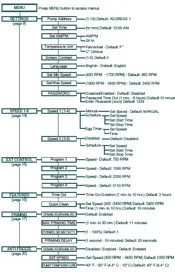
IntelliFlo® Pump Menus
The IntelliFlo® pump menu descriptions are as follows:
Settings: Pump Address
The IntelliFlo® pump address needs to be changed when there is more than one IntelliFlo® pump on an automation system. This allows the automation system to know which pump to send a command.
The “Pump Address” setting is used when the IntelliFlo® pump is connected via the RS-485 COM port to an IntelliTouch®, EasyTouch®, SunTouch® or IntelliComm® system. The default pump address is #1. When connected to EasyTouch®, SunTouch® or IntelliComm® the pump only communicates with address #1. The pump address can be set from 1-16. However, IntelliTouch® can communicate to four (1-4) IntelliFlo® pumps.
Note: IntelliFlo® pumps cannot be connected in series with other pumps.
To access the Settings menu:
1. Be sure the green power LED is on and the pump is stopped.
2. Press the Menu button. “Settings” is displayed.
3. Press the Select button. “Pump Address” is displayed. The Factory default setting is address “1.”
4. To change the pump address, press the Select button. The rst digit “1” selected.
5. Press Up or Down arrow button to change the address number from 1-16.
6. Press the Enter button to save the setting. To cancel any changes, press the Escape button to exit edit mode without saving.
7. Press the Escape button to exit.
Settings: Set Time
Use “Set Time” to set the IntelliFlo® system time. The IntelliFlo® system clock controls all scheduled start and stop times, functions, and programmed cycles. The system clock can store the correct time for up to 96 hours after power is shut off. The IntelliFlo® will retain the time memory for 96 hours before a reset is needed.
To access the Set Time menu:
1. Check that the green power LED is on.
2. Press the Menu button. “Settings” is displayed.
3. Press the Select button. “Pump Address” is displayed.
4. Use the Up or Down arrow button to scroll to “Set Time”
5. Press the Select button. The cursor will appear in the Minutes column.
6. Press Up or Down arrow button to set the time.
7. Press the Enter button to save the setting. To cancel any changes, press the Escape button to exit edit mode without saving.
8. Press the Escape button to exit.
Settings: Set AM/PM or 24 Clock
This setting is for changing the pump’s time clock from regular time (AM/PM) to a 24 hour clock.
For example, Midnight (12:00 AM) is 0000 hr., 8:00 AM is 0800 hr., and 11:00 PM is 2300 hr.
To access the AM/PM or 24 hr. menu:
1. Check that the green power LED is on.
2. Press the Menu button. “Settings” is displayed.
3. Press the Select button. “Pump Address” is displayed.
4. Use the Up or Down arrow button to scroll to “AM/PM.”
5. Press the Select button to change the setting.
6. Press Up or Down arrow button to choose between 24 hr. and AM/PM.
7. Press the Enter button to save the setting. To cancel any changes, press the Escape button to
exit edit mode without saving.
8. Press the Escape button to exit.
Settings: Set Temperature Unit
Use this setting to set the temperature unit to Celsius (°C), or Fahrenheit (°F). The IntelliFlo® AntiFreeze
protection feature (see page 20) can be set to either Fahrenheit or Celsius.
To access the Temperature Units menu:
1. Check that the green power LED is on.
2. Press the Menu button. “Settings” is displayed.
3. Press the Select button. “Pump Address” is displayed.
4. Use the Up or Down arrow button to scroll to “Temperature Units” menu item. The factory default setting is “F” (Fahrenheit).
5. Press the Select button. “F” is displayed.
6. Press Up or Down arrow button to choose between Celsius (°C), or Fahrenheit (°F).
7. Press the Enter button to save the setting. To cancel any changes, press the Escape button to exit edit mode without saving.
8. Press the Escape button to exit.
Settings: Screen Contrast Level
This setting changes the contrast of the LCD screen. The default setting is 3. Screen contrast levels can be adjusted from 1 to 5 units for low or high lighting conditions.
To access the Temperature Units menu:
1. Check that the green power LED is on.
2. Press the Menu button. “Settings” is displayed.
3. Press the Select button. “Pump Address” is displayed.
4. Use the Up or Down arrow to scroll to “Contrast level.
5. Press the Select button. Screen will show current contrast setting number. The default is “3”.
6. Press the Select button to change the setting. Number will highlight.
7. Press the Enter button to save the setting. To cancel any changes, press the Escape button to
exit edit mode without saving.
8. Press the Escape button to exit.
Settings: Language
To access the language menu:
1. Check that the green power LED is on.
2. Press the Menu button. “Settings” is displayed.
3. Press the Select button. “Pump Address” is displayed.
4. Use the Up or Down arrow button to scroll to “Language”.
5. Press the Select button to access the language menu.
6. Press Select to highlight current Language in use.
7. Press the Enter button to select the desired language for the control panel. To cancel any changes, press the Escape button to exit edit mode without saving.
8. Press the Escape button to exit.
Settings: Set Minimum Speed (RPM)
The minimum pump speed can be set from 450 RPM to 1700 RPM. The default setting is 450 RPM.
To access the Set Minimum Speed menu:
1. Check that the green power LED is on.
2. Press the Menu button. “Settings” is displayed.
3. Press the Select button. “Pump Address” is displayed.
4. Use the Up or Down arrow button to scroll to “Set Min Speed”.
5. Press the Select button to change the setting. The cursor will appear in the rst number column (ones)
6. Press Up or Down arrow button to change the pump’s minimum speed setting from 450 to 1700 RPM.
7. Press the Enter button to save the setting. To cancel any changes, press the Escape button to exit edit mode without saving.
8. Press the Escape button to exit.
Settings: Set Maximum Speed (RPM)
The maximum speed can be set from 1900 RPM to 3450 RPM. The default setting is 3450. This setting is used to set the maximum running speed of the pump. When the pump is set to Priming “Enabled” the pump will ramp up to and run at the Maximum Speed setting to attain the prime. A Service Professional must set the Maximum Speed of the pump to not exceed the maximum ow rate of the system on which it will operate.
CAUTION: The Maximum Flow rate setting should be set so the system never operates at or above a 0.635 meter vacuum.
To access the Set Maximum Speed menu:
1. Check that the green power LED is on.
2. Press the Menu button. “Settings” is displayed.
3. Press the Select button. “Pump Address” is displayed.
4. Use the Up or Down arrow button to scroll to “Set Max Speed”.
5. Press the Select button to change the setting. The cursor will appear in the rst number column (ones)
6. Press Up or Down arrow button to change the pump’s maximum speed setting from 1900 to 3450 RPM.
7. Press the Enter button to save the setting. Press the Escape button to exit. To cancel any changes, press the Escape button to exit edit mode without saving.
Settings: Password
When the Password feature is enabled, the pump will enter into password protection mode for a
preprogrammed amount of time after the last button is pressed. The entered password is any combination of four (4) digits.
To access the Password menu:
1. Check that the green power LED is on.
2. Press the Menu button. “Settings” is displayed.
3. Press the Select button. “Pump Address” is displayed.
4. Use the Up or Down arrow button to scroll to “Password”.
5. Press the Select button. The default setting is “Disabled”.
6. Press the Select button to change the setting.
7. Press Up or Down arrow button to change the setting to Enabled”.
8. Press the Enter button to save the setting.
9. Press Down arrow button. “Password Timeout” is displayed.
Factory default time is 10 minutes, this means the pump will go into Password Protection mode 10 minutes after the last control panel key press.
10. Press Select to change time setting from 1 minute to 6 hours.
11. Press the Enter button to save the setting.
12. Press Down arrow button. “Enter Password” is displayed.
13. Press Select to change the setting.
14. Press Left or Right arrow button to move cursor and press up and down arrow to change password number to desired setting.
15. Press the Enter button to save the setting. To cancel any changes, press the Escape button to exit edit mode without saving.
16. Press the Escape button to exit.
Password Protection
Password: The default for this setting is disabled, which means the pump does not have password protection. When this feature is enabled, for a preset amount of time after the last button is pressed, the pump display will prompt for the password before allowing access to the control panel and buttons. The password must be a four (4) numeric digit password. Write down the password and keep in a secure place.
• When the pump is password protected the pump can always be turned off by pressing the Start/Stop button.
• When running the pump in manual mode it cannot be turned back on with the press of the Start/Stop button.
• Pressing the Start/Stop button when the pump is off will return it back to the Running Cycles Mode and will run at the next scheduled run time. If the present time is within the scheduled run time the pump will run the scheduled speed.
• All functions including programming are disabled in Password Protection Mode.
• If any button other than the Start/Stop button is pressed, the screen reads Enter Password.
• When Password Protection is enabled there is a key icon displayed in the upper left side of the LCD.
![]()
Entering Password
• When Password Protection is enabled, press any button (besides the speed button) to prompt the screen to for a password.
• To enter password, use the left and right arrows to move the cursor and the Up and Down arrow button to scroll through the digit then press the Enter button to con rm.
Speed 1-8 (Schedule a Time to Run the Pump)
By setting a start time and a stop time, Speeds 1-8 can be programmed to run a certain speed at a certain time of day. To run a scheduled pump speed, press the Start button (LED on). The LCD screen will display “Running Schedules” when it is ready to run a scheduled speed. If the start button is pressed during a scheduled speed time, the screen will read Running Speed X and will run speed X. (If priming is enabled, it will prime rst at the maximum RPM setting of the pump before running speed X.)
Note: The IntelliFlo® pump will not run the scheduled speeds until the Start/Stop button is pressed (LED on) to place the pump in the “Running Schedule” mode.
To set a schedule to run the pump:
1. Check that the green power LED is on.
2. Press the Menu button. “Settings” is displayed.
3. Use the Up or Down arrow button to scroll to “Speed 1-8”.
4. Press the Select button. “Speed 1” is displayed.
5. Use the Up or Down arrow button to choose the speed you wish to program.
6. Press the Select button. Select Manual, Schedule, or Egg Timer for speeds 1-4. “Disabled” or “Schedule” for speed 5-8 is displayed.
Speeds 1-4 default setting is MANUAL. To create a schedule for speed 1-4 Press Select to highlight manual.Speeds 5-8 default setting is DISABLED. To create a schedule for speed 5-8, Press Select to highlight Disabled.
7. Use the Up or Down arrow button to scroll to “Schedule”.
8. Press the Enter button.
9. Press the Down arrow button. Set speed will be displayed.
10. Press the Select button to change the speed. The rst digit will highlight (ones digit).
11. Use the Up or Down arrow button to change the speed.
12. Press the Enter button to save the setting.
13. Press the Down arrow button. “Set Start Time” is displayed.
14. Press the Select button to change the start time. The cursor will highlight the minute column.
15. Use the Left arrow button to move the cursor to the hour column if desired.
16. Press the Enter button to save the setting.
17. Press Down arrow. “Set Stop Time” is displayed
18. Press the Select button to change the stop time.
19. Press the Enter button to save the setting.
20. Press the Start/Stop button. The LED above the button will light up and the pump will start if within a scheduled time or “Running Schedule” is displayed.
When the pump is running a scheduled speed or a duration speed (egg timer) the countdown time (T 00:01) showing the hours and minutes is displayed on the screen.
Note: Speeds 5-8 can be programmed to operate in Schedule mode only. The IntelliFlo® Variable Speed pump can run eight (8) different speeds at eight (8) programmed start and stop times per day.
Note: When two speeds are scheduled during the same run time the pump will run the higher RPM Speed regardless of Speed # in use
Programming for Constant Run
When programming a schedule for a Speed, the Speed can not be programmed with the same start and stop times. However, it will run without stopping if it is programmed with the Start time set one minute after the stop time. Example: A single speed will run non stop if programmed with a Start Time of 8:00 AM and a Stop time of 7:59 AM.
External Control
This function is for programming speeds that will run when the IntelliComm power center controller sends it a command. For example, Terminal 3 and 4 in IntelliComm will correspond to External Control Program #1. (5 and 6 to Ext Ctrl #2). Use the External Control feature to program the IntelliComm power center.
To access the Ext. Ctrl. menu:
1. Check that the green power LED is on.
2. Press the Menu button. “Settings” is displayed.
3. Use the Up or Down arrow button to scroll to “Ext. Ctrl.”.
5. Press the Select button. “Program 1” is displayed.
6. Press the Select button. “750 RPM’ is displayed.
7. Press the Select button. The “RPM” number will highlight.
8. Press Up or Down arrow button to change the RPM setting.
9. Press the Enter button to save the setting. Note: To cancel any changes, press the Escape button to exit without saving.
10. Press the Escape button.
11. Use the Up or Down arrow button to scroll to “Program 2”.
12. Repeat Step 5 through 9 to set Program 2, 3, and 4.
Features: Quick Clean
This feature can be used to ramp the pump up to a higher RPM for vacuuming, cleaning, adding chemicals, after a storm for extra skimming capability. Press the Quick Clean button (LED on) and then the Start/Stop button (LED on) to start the pump at preset RPM and duration of time. When the Quick Clean cycle is over it will resume regular schedules, it will be in the “Running Schedule” mode.
Quick Clean (Continued)
To access the Quick Clean menu:
1. Check that the green power LED is on.
2. Press the Menu button. “Settings” is displayed.
3. Use the Down arrow button to scroll to “Features”.
5. Press the Select button. “Timeout” is displayed.
6. Press the Down arrow button. “QuickClean” is displayed.
7. Press the Select button. “Set Speed” is displayed.
8. Press the Select button. The “RPM” rst (ones) column will highlight.
9. Use the Up or Down arrow button to change the speed.
10. Press the Enter button to save the setting.
11. Press the Down arrow button. “Time Duration” is displayed.
12. Press the Select button. The cursor will appear in the minutes column.
13. Use the Up or Down arrow button to change the time from 1 minute to 10 hours.
14. Press the Enter button to save the setting. Note: To cancel any changes, press the Escape
button to exit without saving.
15. Press the Escape button to exit.
Features: Time Out
This feature keeps the pump from running for a programmable amount of time. This feature can be used to allow newly glued pipe joints time to dry before circulation of the pool water is resumed. This feature keeps the pump from running for a programmable amount of time. When this feature’s time is up, the pump will be in the “Running Schedule” mode, Start/Stop LED will be lit and ready to turn on at the next scheduled run time.
To access the Time Out menu:
1. Check that the green power LED is on.
2. Press the Menu button. “Settings” is displayed.
3. Use the Down arrow button to scroll to “Features”.
5. Press the Select button. “Timeout” is displayed.
6. Press the Select button. “Timeout Duration” is displayed.
7. Press the Select button. The “Minutes” column will highlight.
8. Press the Left arrow button to scroll to the hours setting. Time out can be set from 1 minute to 10 hours.
9. Press the Enter button to save the setting. Note: To cancel any changes, press the Escape button to exit without saving.
10. Press the Escape button to exit.
Priming
The default setting for Priming is ENABLED. Enabling this feature allows the pump to use its “Flow Technology” to be sure the pump is primed for startup. This feature will not override the “Max Speed” setting. The priming feature ramps the pump to 1800 RPM and pauses for three (3) seconds. If there is suf cient water ow in the pump basket, the pump will go out of priming mode and run its commanded speed. If the ow in the pump basket is not suf cient, the pump will ramp to the “Max Speed” setting and stay there for the priming delay time, which is defaulted at 20 seconds. If there is suf cient water ow in the pump basket at this time, it will go out of priming mode and ramp to the commanded speed. If there is still insuf cient ow in the pump basket, the pump will try to prime at the “Maximum Speed” for the amount of time set up in the “Maximum Priming Time” menu.
Maximum Priming Time: The Maximum Priming Time can be set from 1 minute to 30 minutes. The
default setting is 11 minutes. This is the maximum amount of time the pump will try to prime before giving an error. However if the pump does not see a suf cient amount of water in the pump basket this can cause the pump to report a Priming Dry Alarm within seconds of the beginning of the priming cycle.
Priming Dry Alarm: An insuf cient amount of water in the basket during priming will cause the pump to report a Priming Dry Alarm. The basket should be lled with water and the pump restarted when this alarm occurs.
Note: When a Priming Dry Alarm takes place it will try to restart after 10 minutes.
Primed Sensitivity: The primed sensitivity can be set from 1% to 100%. The factory default setting is 1% meaning that the pump is at its most sensitive setting in regards to determining if the pump has attained a prime or not. Increasing this number will decrease the amount of ow needed for the pump to sense that it is primed. Making this number too high could cause the pump to think it has attained a prime and evacuated the air from the system when it has not. If the system is such, that the pump has trouble coming out of the priming mode and it is evident that the pump basket is full of water and owing then the Primed Sensitivity number can be increased.
Priming Delay: The priming delay can be set from 1 second to 10 minutes. The default setting is 20 seconds. This means the pump will ramp to 1800 RPM and stay there for three (3) seconds which it will always do in the hard Priming Mode. If there is suf cient ow in the pump basket, the pump will then go out of priming mode and ramp to its commanded speed. If there is insuf cient water ow in the pump basket, the pump will ramp to the Max Speed Setting and stay there for the default time of 20 seconds. It may be necessary to increase the prime delay to allow the system to stabilize before the pump goes into running mode. If the pump errors out immediately after priming, then increasing the Priming Delay time may correct the issue.
When the pump is connected to an automation system and the “Maximum Prime Time” feature is enabled, it will remain active.
To access the Priming menu:
1. Check that the green power LED is on and press the Menu button. “Settings” is displayed.
2. Use the Down arrow button to scroll to “Priming”.
3. Press the Select button. The factory default is set to priming “Enabled“.
4. To disable priming, press the Select button.
5. Use the Up arrow button. “Disabled” is displayed.
6. Press the Enter button.
7. Press the Down arrow button. Screen will read “Max Priming Time”. The factory default is set to 11 minutes.
8. Press the Select button to change the setting. The cursor will highlight the minutes column.
9. Use the Up or Down arrow button to change the time from 1 minute to 30 minutes..
10. Press the Enter button to save the setting.
11. Press the Down arrow button. The screen will read “Primed Sensitivity”. The default for this setting being “1”.
12. Press the Select button to change the setting. The cursor will highlight the number.
13. Use the Up or Down arrow button to change the time from 1% to 100%. Increasing the number makes the Priming less sensitive.
14. Press Enter to save.
15. Press the Down arrow button. Screen will read “Priming Delay”. The default for this setting is 20 seconds.
16. Press the Select button to change the Setting.
17. Use the Up or Down arrow button to change the setting from 1 second to 10 minutes. Caution: Increasing the Priming Delay causes the pump to stay in the priming mode longer.
18. Press the Enter button to save the setting. Note: To cancel a change, press the Escape button instead of the Enter button to exit without saving.
19. Press the Escape button to exit.
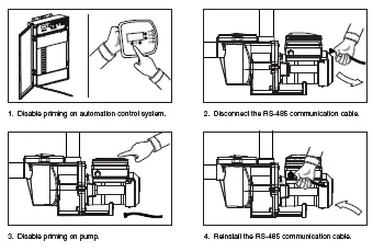
Disable Priming Feature on the Pump
When the IntelliFlo® pump is connected to an automation control system, (IntelliTouch, EasyTouch or SunTouch), the priming feature on the pump cannot be disabled by the external automation control system only. If priming is enabled on start-up, the IntelliFlo® responds to its internal settings before responding to commands from an automation control system. If the IntelliFlo® pump is connected to an automation control system and priming is not desired, disable the priming feature on both the pump and the automation control system.
To disable priming with an automation control system:
1. Disable the priming feature on the automation control system at the load center or using an IntelliTouch or EasyTouch remote. (Refer to the automation control system user’s guide for additional information).
2. Temporarily disconnect the RS-485 communication cable.
3. Open the LCD screen lid to disable priming on the pump. Press the MENU button, use the arrow buttons to scroll and select “Priming”, then select “Disabled” (the factory default is set to “Enabled”). Press Escape to exit the menu.
4. Once priming is disabled, reinstall the RS-485 communication cable.
Anti Freeze
This feature allows you to set a speed (450 RPM -3450 RPM) that will run when the pump goes into anti freeze mode. The temperature level that you wish anti freeze mode to start can also be set.
IMPORTANT NOTE: This feature is for protection of the pump. Do not depend on the antifreeze feature for freeze protection of the pool. Certain situations could cause the pump to sense a different temperature than actual air temperature. Your automation systems air temperature sensor should be used to sense actual temperature. For example, if the pump is located indoors, the temperature of the room does not indicate the outdoor temperature. The pump does not sense the water temperature.
To access the AntiFreeze menu:
1. Check that the green power LED is on.
2. Press the Menu button. “Settings” is displayed.
3. Use the Down arrow button to scroll to “AntiFreeze”.
4. Press the Select button. The factory default is AntiFreeze “Enabled“.
5. To disable AntiFreeze. Press the Select button, “Enabled” will highlight.
6. Use the Up arrow button. “Disabled” is displayed.
7. Press the Enter button.
To program AntiFreeze when enabled:
8. Press the Down arrow button.“Set Speed” is displayed. The factory default is 1000 RPM.
9. Press the Select button to change the setting. The cursor will highlight the rst column (ones).
10. Use the Up or Down arrow button to select 450 – 3450 RPM.
11. Press the Enter button to save the setting.
12. Press the Down arrow button. “Pump Temperature” is displayed. This is the temperature the pump will activate AntiFreeze. The factory default is 40° F (4.4° C).
13. Press the Select button to change the setting. The cursor will highlight the rst column (ones).This setting can be changed from 40° F to 50° F (4.4° C – 10° C).
14. Press the Enter button to save the setting. Note: To cancel any changes, press the Escape button to exit without saving.
15. Press the Escape button to exit.
Priming the pump for the fi rst time, or after service
The IntelliFlo® must be primed before starting the pump for the rst time. To prime a pump means lling the pump and suction pipe with water. This process evacuates the air from all the suction lines and the pump. It may take several minutes to prime depending on the depth of water, pipe size and length. It is easier to prime a pump if you allow all the air to escape from the pump and pipes. The water cannot enter unless the air can escape. Pumps do not hold prime, the pool piping system has that task.
CAUTION – To avoid permanent damage to the IntelliFlo® pump, before starting the pump, fi ll the IntelliFlo® housing strainer with water so that the pump will prime correctly. If there is no water in the strainer the pump will not prime.
• Do not allow the pump to run dry. Running the pump dry may damage the seals, causing leakage and fl ooding.
• Do not add chemicals to the system directly in front of pump suction. Adding undiluted chemicals may damage the pump and will void the warranty.
• Open gate valves before starting system.
• Be sure to release all air from fi lter and piping system.
• The IntelliFlo® pump is a variable speed pump. Typically the lower speeds are used for fi ltration and heating. The higher speeds can be used for spa jets, water features, and priming.
CAUTION – Before starting this procedure, fi rst read the following:
Before removing the pump lid:
1. Press the Stop button if the pump is running before proceeding.
2. Disconnect the communication cable from the pump.
3. Disconnect main power supply
4. Close the gate valves in suction and discharge pipes.
5. Release all pressure from pump and piping system.
6. Never tighten or loosen the clamp while the pump is operating.
WARNING – If the pump is being pressure tested, release all pressure before removing trap cover. Do not block the pump suction while the pump is running. If a body part blocks the pump suction it may cause severe or fatal injury. Small children using the pool must ALWAYS have close adult supervision.
WARNING : FIRE and BURN HAZARD – The pump motor may run at a high temperatures. To reduce the risk of fi re, do not allow leaves, debris, or foreign matter to collect around the pump motor. To avoid burns when handling the motor, shut off the motor and allow it to cool for 20 minutes before trying to work on it. The IntelliFlo® provides an automatic internal cutoff switch to protect the motor from heat damage during operation.
Priming the Pump
NOTICE: If you replace the o-ring with a non-lubricated o-ring, you may need to apply a silicone based lubricant.
• Clean and inspect o-ring; reinstall on trap cover.
• Replace trap cover on trap; turn clockwise to tighten cover.
NOTICE: Tighten the pump lid by hand only (no wrenches).
Priming time will depend on vertical length of suction lift and horizontal length of suction piping. If pump does not prime, be sure that all valves are open, suction pipe end is under water, pump suction is below water level, and that there are no leaks in suction pipe.
To prime the IntelliFlo® pump:
1. Turn the pump clamp and lid in a counter-clockwise direction until it stops and remove them.
2. Fill the pump strainer pot with water.
3. Check the system and ensure water has an open path for free system ow.
4. Reinstall the pump clamp and lid onto the strainer pot. The pump is now ready to prime.
5. Be sure all electrical connections are clean and tight.
6. Open the air release valve on the lter, and stand clear of the lter.
7. Switch the pump on at the circuit breaker. Ensure that the green power light is on.
8. Press the Speed 1 button to select the pump speed of 750 RPM.
9. Press the Start button to start the pump. Use the Up/Down button to increase the speed as necessary to prime the pump.
10. When water comes out of the air release valve, close the valve. The system should now be circulating water back to the pool without air bubbles showing in either the hair and lint pot or at the pool return ttings.
11. Use the Up/Down button to adjust the operating speed as desired.
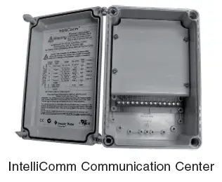
External Control with IntelliComm® Communication Center
The IntelliFlo® pump can be remotely controlled by the Pentair Water Pool and Spa IntelliComm Communication Center using the RS-485 communications cable. The IntelliComm provides four pairs of input terminal connections. These inputs are actuated by either 15 – 240 VAC or 15 – 100 VDC. Using the device’s inputs, the programmed IntelliFlo® pump speeds can be controlled.
Note: For the IntelliFlo® pump to accept commands from IntelliComm, the pump must be in the “Running Schedules” mode (LED above the Start/Stop button lit).
If more than one input is active the highest number will be communicated to the IntelliFlo® pump.
The IntelliComm will always communicate to pump using ADDRESS #1.
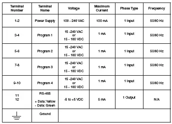
Program number priority is as follows: Example: If programs 1 and 2 are activated, program 2 will run, regardless of the assigned speed (RPM). The higher program number (2 being higher) will always take priority. The following table shows the wiring terminal descriptions for IntelliComm.
External Control
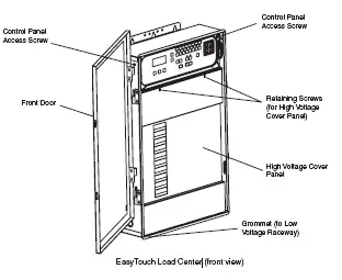
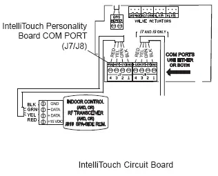
Connecting IntelliFlo® to EasyTouch® and IntelliTouch® System
The IntelliFlo® pump can be controlled by an EasyTouch or IntelliTouch automation system via the RS-485 communication cable. In this con guration, EasyTouch/IntelliTouch starts, stops and controls the speed of the IntelliFlo® pump. When the EasyTouch/IntelliTouch does this, it rewrites the IntelliFlo® pump memory, which can take several seconds. This causes a delay after a command is given on the EasyTouch/IntelliTouch control panel until the IntelliFlo® pump physically responds.
The IntelliFlo® pump control panel is disabled when communicating with the EasyTouch/IntelliTouch system. Note that EasyTouch/IntelliTouch will not start communicating with the IntelliFlo® pump until the pump is assigned to a circuit. The IntelliFlo® pump default pump address is one which is the only address that works with EasyTouch. See page 9 for details about how to check the pump address and change if necessary. For more information, refer to the EasyTouch User’s Guide (P/N 520584). To connect the IntelliFlo® pump communication cable to EasyTouch or IntelliTouch load center:
1. CAUTION – Switch the main power off to the EasyTouch load center.
2. Unlatch the two enclosure door spring latch, and open the door.
3. Remove the two retaining screws securing the high voltage cover panel, and remove it from the enclosure.
4. Loosen the two access screws securing the control panel.
5. Lower down the hinged control panel to access the EasyTouch or IntelliTouch circuit board.
6. Route the communication cable into the plastic grommet (located on the lower left side of the load center), up through the low voltage raceway to the EasyTouch or IntelliTouch circuit board.
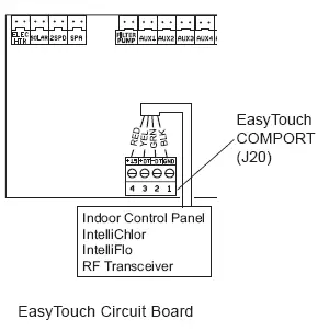
7. Strip back the cable conductors 6 mm (1/4”). Insert the two wires into the COM port screw terminals on the EasyTouch/IntelliTouch circuit board. Secure the wires with the screws.
8. EasyTouch COM port (J20): Connect the GREEN (#2) and YELLOW (#3) wires to the
COM port screw terminals (#2 and #3). Be sure to match the color coding of the wires; YELLOW to YELLOW and GREEN to GREEN. The Red wire is not connected. Secure the wires with the screws.
IntelliTouch COM port (J7/8): Connect the GREEN (#2) and YELLOW (#3) wires to the
COM port (J20) screw terminals (#2 and #3). Be sure to match the color coding of the wires; YELLOW to YELLOW and GREEN to GREEN. The Red wire is not connected. Secure the wires with the screws.
Note: Multiple wires may be inserted into a single screw terminal.
9. Close the control panel into its original position and secure it with the two screws.
10. Install the high voltage cover panel and secure it with the two retaining screws.
11. Close the load center front door. Fasten the spring latch.
12. Switch the power on to the load center.
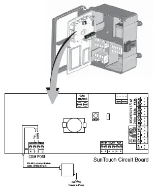
Connecting the IntelliFlo® pump to a SunTouch® System
The IntelliFlo® pump can be controlled by a SunTouch system via the RS-485 communication cable.
WARNING – Switch OFF main system power to the SunTouch Power Center before making any connections.
To connect the IntelliFlo® pump two wire RS-485 communication cable to the SunTouch circuit board:
1. Unlatch the front door of the SunTouch power center, and open the door.
2. Loosen the retaining screw on front panel. Open the hinged front panel to access the electronics compartment.
3. Route the two conductor cable up through the power center grommet opening located on the left side, and up through the low voltage raceway to the motherboard.
4. Strip back the cable conductors 6 mm (1/4”). Insert the wires into the screw terminals (provided). Secure the wires with the screws. Be sure to match the color coding of the wires; YELLOW to YELLOW and GREEN to GREEN.
5. Insert the connector on the COMPORT (J11) screw terminal on the SunTouch circuit board.
6. Close the control panel and secure it with the retaining screw.
7. Close the front door. Fasten the spring latch.
The following information describes how to service and maintain the IntelliFlo® Variable Speed pump.
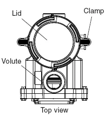
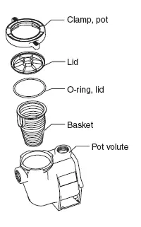
Pump Strainer Basket
The strainer, sometimes referred to as the “Hair and Lint Pot,” is in front of the of the pump. Inside there is a basket which must be kept clean of leaves and debris at all times. View the basket through the top see through lid to inspect for leaves and debris.
Regardless of the length of time between lter cleaning, it is most important to visually inspect the hair and lint pot basket at least once a week. A dirty basket will reduce the ef ciency of the lter and possibly the heater.
WARNING — DO NOT open the strainer pot if pump fails to prime or if pump has been operating without water in the strainer pot. Pumps operated in these circumstances may experience a build up of vapor pressure and may contain scalding hot water. Opening the pump may cause serious personal injury. In order to avoid the possibility of personal injury, make sure the suction and discharge valves are open and that the strainer pot is cool to the touch, then open with extreme caution.
CAUTION — To prevent damage to the pump and fi lter and for proper operation of the system, clean pump strainer and skimmer baskets regularly.
Pump Strainer Basket Service
If the IntelliFlo® pump is installed below the water level of the pool, close the return and suction lines before opening the hair and lint pot on the pump.
1. Press the Stop button to stop the pump and switch off the pump at the circuit breaker.
2. Disconnect the communication cable from the IntelliFlo® pump.
3. Relieve pressure in the system.
4. Turn the clamp and lid in a counter-clockwise direction until it stops.
5. Remove the clamp and lid.
6. Remove the basket and put the debris into the trash and rinse out the basket. If the basket is cracked, replace the basket.
7. Replace the basket and ll the pump pot and volute with water up to the inlet port.
8. Clean the cover, o-ring, and sealing surface of the pump pot. Grease the o-ring with a silicone based lubricant.
9. Reinstall the lid by placing the clamp and the lid on the pot.
10. Be sure that the lid o-ring is properly placed. Seat the clamp and lid then turn clockwise until the
handles are horizontal as shown.
11. Reconnect the communication cable to the pump if required.
12. Switch the power ON at the circuit breaker. Reset the pool time clock to the correct time.
WARNING – FILTER OPERATES UNDER HIGH PRESSURE. WHEN ANY PART OF THE CIRCULATING SYSTEM (e.g., LOCK RING, PUMP, FILTER, VALVES, ETC.) IS SERVICED, AIR CAN ENTER THE SYSTEM AND BECOME PRESSURIZED. PRESSURIZED AIR CAN CAUSE THE LID TO BLOW OFF WHICH CAN RESULT IN SEVERE INJURY, DEATH, OR PROPERTY DAMAGE. TO AVOID THIS POTENTIAL HAZARD, FOLLOW THESE INSTRUCTIONS.
13. Open the manual air relief valve on top of the lter.
14. Stand clear of the lter. Press the Start button on the pump.
15. Bleed air from the lter until a steady stream of water comes out.
16. Close the manual air relief valve.
Motor Service
1. Protect from heat:
• Shade the motor and controller from the sun.
• Any enclosure must be well ventilated to prevent overheating. Particular attention should be paid to the motor fan cover and the cooling ns between the drive and the motor.
• Provide ample cross ventilation.
2. Protect against dirt:
• Protect from any foreign matter or splashing water.
• Do not store (or spill) pool chemicals near the motor.
• Avoid sweeping or stirring up dust near the motor while it is operating.
• If a motor has been damaged by dirt it voids the motor warranty.
3. Protect against moisture:
• Protect from splashing pool water.
• Protect from the weather.
• Protect from lawn sprinklers.
• If a motor has become wet, let it dry before operating. Do not allow the pump to operate if it has been ooded.
• If a motor has been damaged by water it voids the motor warranty.
Note: Do not wrap motor and controller with plastic or other air tight materials during winter storage. The motor and controller may be covered during a storm, winter storage, etc., but never when operating or expecting operation.
Winterizing
To protect the IntelliFlo® pump electronics from damage due to freezing conditions, the pump will switch itself on to generate internal heat when the air temperature drops below 4.4° C (40° F). The IntelliFlo® pump “Anti Freeze” feature is not intended to protect the system plumbing from freezing.
The Anti Freeze temperature feature is adjustable and can be changed from 4.4° – 10° C (40° – 50° F).See page 10 for more information.
1. If the air temperature drops below 4.4° C (40° F) the water in the pump can freeze and cause damage. Freeze damage is not warrantable.
2. To prevent freeze damage follow the procedures listed below.
• Shut off electrical power for the pump at the circuit breaker.
• Drain the water out of the pump by removing the two thumb-twist drain plugs located at the bottom of the volute. Store the plugs in the pump basket.
• Cover the motor to protect it from severe rain, snow and ice.
• Do not wrap the motor in plastic. It will cause condensation and rust on the inside of the motor.
Note: In mild climate areas, when temporary freezing conditions may occur, run your ltering equipment all night to prevent freezing.
Priming the pump after service
Before a system start-up, the pump and system must be manually primed. Be sure to reopen valves before operating. To prime IntelliFlo® pump, the strainer pot must be lled with water.
CAUTION – DO NOT run the pump dry. If the pump is run dry, the mechanical seal will be damaged and the pump will start leaking. If this occurs, the damaged seal must be replaced. ALWAYS maintain proper water level in your pool. Continued operation in this manner could cause a loss of pressure, resulting in damage to the pump case, impeller and seal.
For instructions about how to prime the IntelliFlo® pump, refer to “Priming the pump for the rst time or after service”
Installation and Removal
The following information describes how to install the IntelliFlo® pump.
Installing the IntelliFlo® Pump Only a quali ed service person should install the IntelliFlo® pump. Refer to “Important Warning And Safety Instructions” on pages iii to vii for additional installation guidance and safety information.
IntelliFlo® Pump Kit Contents
IntelliFlo® Variable Speed pump, FWC cover, gasket, screws, communication cable, and the Installation and User’s Guide (this manual).
Location
1. Install the pump as close to the pool or spa as possible. To reduce friction loss and improve ef ciency,
use short and direct suction and piping returns.
2. Install a minimum of 5 feet (1.52 meters) from the inside wall of the pool and spa. Canadian installations require a minimum of 9.8 feet (3 meters) from pool water.
3. Install the pump a minimum of 3 feet (0.9 meters) from the heater outlet.
4. Do not install the pump more than 10 feet (3 meters) above the water level or 3 feet (0.91 meters) below water level.
5. Install the pump in a sheltered well ventilated location protected from excessive moisture, (i.e., rain, sprinklers, etc.).
6. For hot tubs and spas, do not install within an outer enclosure or beneath the skirt of a hot tub or spa.
7. Install the pump with a rear clearance of at least 3 inches (76.2 mm) so that the motor can be removed easily for maintenance and repair.
Piping
• For improved pool plumbing, it is recommended to use a larger pipe size. When installing the inlet and outlet ttings (male adaptors), use thread sealant.
• Do not install 90° elbows directly into pump inlet or outlet. A valve, elbow or tee installed in the suction line should be no closer to the front of the pump than ve times the suction line pipe diameter (i.e., 2 inch (5.1 cm) pipe requires a 10 inch (254 mm) straight run in front of the suction inlet of the pump). This will help the pump prime faster and last longer.
• Flooded suction systems should have gate valves installed on suction and discharge pipes for maintenance, however, the suction gate valve should be no closer than ve times the suction pipe diameter as described above.
Electrical
• A means for disconnection must be incorporated in the xed wiring in accordance with the wiring rules.
• The pump is to be supplied through a residual current device (RCD) having a rated residual operating current not exceeding 30mA.
Wiring the IntelliFlo® Pump
To connect the IntelliFlo® pump to an AC power source:
1. Be sure all electrical breakers and switches are turned off before wiring motor.
2. Be sure that the wiring voltage is 230 VAC ± 10%.
3. Use #12 AWG for wire runs up to 100 feet (30.5 meters) and #10 AWG for lengths longer than
100 feet (30.5 meters). When in doubt use a heavier gauge (larger diameter) wire. Heavier gauge
will allow the motor to run cooler and more ef cient.
4. Be sure all electrical connections are clean and tight.
5. Cut the wires to the appropriate length so they do not overlap or touch when connected.
6. Permanently ground the motor using the green ground wire, as shown below. Use the correct wire size and type speci ed by National Electrical Code. Be sure the ground wire is connected to an electrical service ground.
7. Bond the motor to the pool structure in accordance with the National Electrical Code. Use a solid copper bonding conductor not smaller than 8 AWG. Run a wire from the external bonding lug to the pool bonding structure, as shown below.
8. Connect the wire from the accessible bonding lug on the motor to all metal parts of the swimming pool, spa, or hot tub structure and to all electrical equipment, metal conduit, and metal piping within 5 feet of the inside walls of the swimming pool, spa, or hot tub. For Canada, a 6 AWG or larger solid copper bonding conductor is required.
9. The pump should be permanently connected to either a circuit breaker, 2-pole timer or 2-pole relay. If AC power is supplied by a GFCI circuit breaker, use a dedicated circuit breaker that has no other electrical loads.
10. IMPORTANT: When connecting the pump to an automation system (IntelliTouch, EasyTouch, SunTouch and IntelliComm), continuous power must be supplied to the pump by connecting it directly to the circuit breaker. When using an automation system, be sure that no other lights or appliances are on the same circuit.
NOTE: When the IntelliFlo® is started and stopped by removing power with a relay or timer, a two-pole device should be used to apply and remove power to both POWER LINE TERMINALS.
p
Pentair offers 2-Pole 20 Amp GFCI breakers (P/N PA220GF) which offer 6 milliamp personnel protection while meeting NEC 2008 Standards for Pool Pumps.
Pump Disassembly
WARNING — Always disconnect power to the pool pump at the circuit breaker and disconnect the communication cable before servicing the pump. Failure to do so could result in death or serious injury to serviceman, pool users or others due to electric shock. Read all servicing instructions before working on the pump.
WARNING — DO NOT open the strainer pot if pump fails to prime or if pump has been operating without water in the strainer pot. Pumps operated in these circumstances may experience a build up of vapor pressure and may contain scalding hot water. Opening the pump may cause serious personal injury. In order to avoid the possibility of personal injury, make sure the suction and discharge valves are open and strainer pot temperature is cool to touch, then open with extreme caution.
CAUTION — Be sure not to scratch or mar the polished shaft seal faces; seal will leak if faces are damaged.
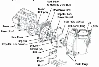
All moving parts are located in the rear subassembly of the IntelliFlo® pump.
Tools required:
• 3/32 inch Allen head wrench
• Two (2) 9/16 inch open end wrenches
• 1/4 inch at blade No. 2 or 3 Phillips head screwdriver
• Adjustable wrench
To remove and repair the pump mechanical seal, perform the following procedures:
1. Switch off the pump circuit breaker at the main panel.
2. Disconnect the RS-485 communication cable from the pump (if connected to pump).
3. Drain the pump by removing the drain plugs. No tools required.
4. Use the 9/16 inch wrenches to remove the six bolts that hold the housing (strainer pot/volute) to the rear subassembly.
5. Gently pull the two pump halves apart, removing the rear subassembly.
6. Use a 3/32 inch Allen head wrench to loosen the two holding screws located on the diffuser.
7. Hold the impeller securely in place and remove the impeller lock screw by using a Phillips head screwdriver. The screw is a left-handed thread and loosens in a clockwise direction.
8. Use a at blade screwdriver to hold the motor shaft. The motor shaft has a slot on the end which is accessible through the center of the fan cover.
Note: An adjustable wrench may be used to hold the screwdriver shaft in place. Use locking pliers instead if your screwdriver has a round shaft.
9. To unscrew the impeller from the shaft, twist the impeller counterclockwise.
10. If the seal needs replacing, remove the white-colored, rotating portion of the mechanical seal from the impeller.
11. Remove the four bolts from the seal plate to the motor, using a 9/16 inch wrench.
12. Place the seal plate face down on a at surface and tap out the carbon spring seat.
13. Clean the seal plate, seal bore, and the motor shaft.
Pump Disassembly
Shaft Seal Replacement
The Shaft Seal consists primarily of two parts, a rotating member and a ceramic seal. The pump requires little or no service other than reasonable care, however, a shaft seal may occasionally become damaged and must be replaced. Note: The polished and lapped faces of the seal could be damaged if not handled with care.
Pump Reassembly/Seal Replacement
1. When installing the replacement shaft seal, use silicone sealant on the metal portion before pressing into the seal plate as shown. Note: Use extreme care when applying sealant. Ensure that no sealant contacts the seal plate surface or the ceramic seal. Allow sealant to cure overnight before reassembling.
2. Before installing the rotating portion of the seal into the impeller, be sure the impeller is clean. Use a light density soap and water to lubricate the inside of the seal. Press the seal into the impeller with your thumbs and wipe off the ceramic and carbon faces with a clean cloth.
3. Remount the seal plate to the motor.
4. Grease the motor shaft thread and screw impeller onto the motor shaft.
5. Screw in the impeller lock screw (counterclockwise to tighten).
6. Remount the diffuser onto the seal plate. Be sure the plastic pins and holding screw inserts are aligned.
7. Grease the diffuser o-ring and seal plate gasket prior to reassembly.
8. Assemble the motor subassembly to the pump housing by using the two (2) through bolts for proper alignment. Do not tighten the through bolts until all six (6) bolts are in place and nger tightened.
9. Fill the pump with water.
10. Reinstall the pump lid and plastic clamp. See “Pump Strainer Basket Service” on page 27 for details
11. Reconnect the RS-485 communication cable to the pump.
12. Prime the pump, see page 17 and 22.
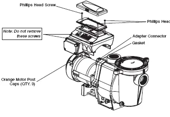
Drive Assembly Removal and Installation
WARNING – To avoid dangerous or fatal electrical shock hazard, switch OFF power to motor before working on pump or motor.
CAUTION – To avoid electrical hazard, do not remove the four tamper proof bits from the motor assembly.
To remove the IntelliFlo® drive and control panel from the motor assembly:
1. Be sure all electrical breakers and switches are turned off before removing the drive.
2. Disconnect the RS-485 communication cable from the pump.
3. Open the control panel cover.
4. Remove the three Phillips head screws securing the drive to the motor assembly as shown.
5. Lift up the drive assembly and remove it from the motor adapter located on top of the motor assembly.
Note: Be careful not to remove the gasket between the drive and motor, it is critical in keeping moisture out of the drive and motor. Replace the gasket if damaged. Do not reassemble with a damaged or missing gasket.
To install the IntelliFlo® drive assembly onto the motor assembly:
1. Be sure all electrical breakers and switches are turned off before installing the drive.
2. Be sure that the gasket between the drive and motor is in place. It is critical in keeping moisture
out of the drive and motor. Replace the gasket if damaged. Do not reassemble with a damaged or missing gasket.
3. Verify that the three (3) orange motor post caps are in position before placing the drive on the motor assembly.
4. Align the drive assembly with the motor adapter and seat the drive on the motor assembly.
5. Secure and tighten the drive assembly with the three Phillips head screws.
Troubleshooting
CAUTION – Before installing this product, read and follow all warning notices and instructions on page iii – vii.
Alerts and Warnings
The IntelliFlo® pump displays all alarms and warnings on the control panel display. When an alarm or warning condition exists, the corresponding LED will be lit on the display. All control panel buttons are disabled until the alarm or warning is acknowledged with the Enter button. Press the Reset button to clear the alarm once the fault condition has been resolved. Note: The IntelliFlo® pump will not start
if the impeller is rotating. The alerts and warnings are:
• Power out failure: The incoming supply voltage is less than 170 VAC. The drive faults to protect itself from over current. The drive contains capacitors that keep it powered up long enough to save the current run parameters. If power is restored during this process, approximately 20 seconds, the drive will not restart until completed.
• Priming error: If the pump is not de ned as primed within the “Max Priming Time” it will stop and generate a “Priming Alarm” for 10 minutes, then attempt to prime again. The “Max Priming Time” is set by the user on the priming menu as discussed on page 18. If the IntelliFlo® cannot prime within ve attempts it will generate a permanent alarm that must be manually reset.
• Overheat alert: If the drive temperature gets above 54.4° C (130° F) the IntelliFlo® will slowly reduce speed until the over temperature condition clears.
• Anti-freezing: When active, the motor will run at the preset RPM until the drive temperature increases above the minimum. The pump’s internal antifreeze protection is disabled when connected to an automation system. Freeze protection is provided by selecting YES at the ON WITH FREEZE portion of the IntelliTouch’s appropriate circuit function menu. To re-enable the internal antifreeze protection, the power to the drive must be cycled off then back on.
• Over current: Indicated that the drive is overloaded or the motor has an electrical problem. The drive will restart 20 seconds after the over current condition clears.
• Over voltage: Indicates excessive supply voltage or an external water source is causing the pump and motor to rotate thereby generating an excessive voltage on the drives internal DC buss. The drive will restart 20 seconds after the over voltage condition clears.
General IntelliFlo® Troubleshooting Problems
Use the following general troubleshooting information to resolve possible problems with your IntelliFlo® pump.
Note: Turn off power to unit prior to attempting service or repair.
Replacement Parts
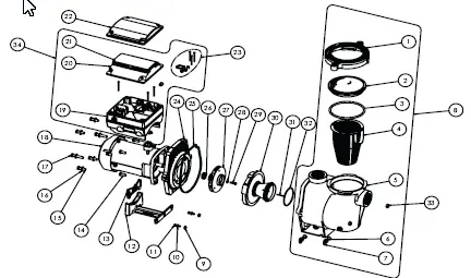
IntelliFlo® Variable Speed Replacement Parts
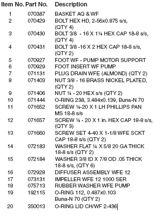
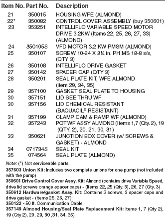
Note: (*) Not serviceable parts.
357603 Union Kit: Includes two complete unions for one pump (not included
with the pump) 350601 Drive Control Cover Assy. Kit: Almond (contains drive Variable Speed, drive lid screws orange spacer caps) – (Items 22, 25 (Qty. 3), 26, 27 (Qty. 3) 350612 Hardware/gasket Assy. Kit: Contains 3 screws, 3 spacer caps and
drive gasket – (Items 25, 26, 27) 350122 – 50 ft. Communication Cable 357149 Almond Housing/Seal Plate Replacement Kit: Items 1, 7 (Qty 2), 19 (Qty 2), 20, 29, 30 ,31, 34, 35)
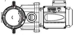
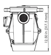
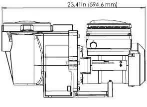
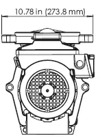
IntelliFlo® Pump Dimensions
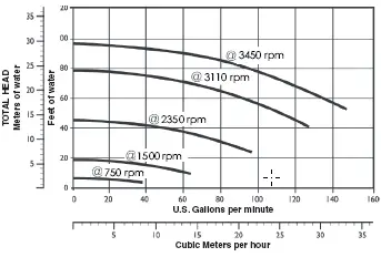
IntelliFlo® Flow Pump Performance Curve
IntelliFlo® Electrical Specifi cations
Circuit Protection: Two-pole 20 AMP device at the Electrical Panel.
Input: 230 VAC, 50/60 Hz, 3200 Watts, 1 phase
SAVE THESE INSTRUCTIONS
Customer Service / Technical Support
If you have questions about ordering Pentair Water Pool and Spa (“Pentair”) replacement parts, and pool products, please use the following contact information:
Customer Service (8 A.M. to 5 P.M. — Eastern and
Pacific Times)
Phone: (800) 831-7133
Fax: (800) 284-4151
Web site
visit www.pentairpool.com or www.staritepool.com to
find information about Pentair products.*
Technical Support
Sanford, North Carolina (8 A.M. to 5 P.M. ET)
Phone: (919) 566-8000
Fax: (919) 566-8920
Moorpark, California (8 A.M. to 5 P.M. PT)
Phone: (805) 553-5000 (Ext. 5591)
Fax: (805) 553-5515