IMPORTANT
SAFETY RULES
Read, understand, and follow
all instructions carefully before installing and using this product.
 For illustrative purposes only. Accessories may not be provided with pool.
METAL FRAME POOL
10′ – 24′ (305 cm – 732 cm) models
Don’t forget to try these other fine Intex products: Pools, Pool Accessories, Inflatable Pools and In-Home Toys, Airbeds and Boats available at fine retailers or visit our website listed below. Due to a policy of continuous product improvement, Intex reserves the right to change specifications and appearance, which may result in updates to the instruction manual without notice.
IMPORTANT!
DO NOT RETURN PRODUCT TO STORE
To purchase parts and accessories or to obtain non-technical assistance,
Visit www.intexcorp.com
For technical assistance and missing parts call us toll-free (for U.S. and Canadian Residents): 1-800-234-6839
Monday through Friday, 8:30am to 5:00pm Pacific Time 087-*PO-R0-2006
Special Introductory note:
Thanks for buying an Intex pool. Please read this manual before setting up your pool. This information will help extend the pool life and make the pool safer for your family’s enjoyment. A team of 2-3 people is recommended for pool set up. Additional people will speed up the installation. No tools are required for the assembly.
IMPORTANT SAFETY RULES
Read, Understand and Follow All Instructions Carefully Before Installing and Using this Product.
- Continuous and competent adult supervision of children and the disabled is required at all times.
- Secure all doors, windows, and safety barriers to prevent unauthorized, unintentional, or unsupervised pool entry.
- Install a safety barrier that will eliminate access to the pool for young children and pets.
- Pool and pool accessories are to be assembled and disassembled by adults only.
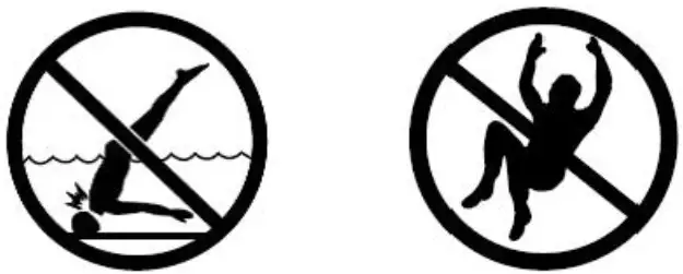
- Never dive, jump or slide into an above-ground pool or any shallow body of water.
- Failure to set up the pool on flat, level, compact ground, or overfilling could result in the pool’s collapse and the possibility that a person lounging in the pool could be swept out/ejected.
- Do not lean, straddle, or exert pressure on the inflatable ring or top rim as injury or flooding could occur. Do not allow anyone to sit on, climb, or straddle the sides of the pool. • Remove all toys and flotation devices from, in, and around the pool when it is not in use. Objects in the pool attract young children.
- Keep toys, chairs, tables, or any objects that a child could climb on at least four feet (1.22 meters) away from the pool.
- Keep rescue equipment by the pool and clearly post emergency numbers at the phone closest to the pool. Examples of rescue equipment: coast guard approved ring buoy with attached rope, strong rigid pole not less than twelve feet (12’) [3.66m] long.
- Never swim alone or allow others to swim alone.
- Keep your pool clean and clear. The pool floor must be visible at all times from the outside barrier of the pool.
- If swimming at night use properly installed artificial lighting to illuminate all safety signs, ladders, pool floor and walkways.
- Stay away from the pool when using alcohol or drugs/medication.
- Keep children away from pool covers to avoid entanglement, drowning, or another serious injury.
- Pool covers must be completely removed before pool use. Children and adults cannot be seen under a pool cover.
- Do not cover the pool while you or anyone else is in the pool.
- Keep the pool and pool area clean and clear to avoid slips and falls and objects that may cause injury.
- Protect all pool occupants from recreational water illnesses by keeping the pool water sanitized. Don’t swallow the pool water. Practice good hygiene.
- All pools are subject to wear and deterioration. Certain types of excessive or accelerated deterioration can lead to an operation failure, and can ultimately cause the loss of large quantities of water from your pool. Therefore, it is very important that you properly maintain your pool on a regular basis.
- This pool is for outdoor use only.
- Empty pool completely when not in use for a longer period and safely store the empty pool in such a way that it does not collect water from rain or any other source. See storage instructions.
- All electrical components shall be installed in accordance with Article 680 of the National Electrical Code 1999 (NEC ® ) “Swimming Pools, Fountains and Similar Installations” or its latest approved edition.
POOL BARRIERS AND COVERS ARE NOT SUBSTITUTES FOR CONTINUOUS AND COMPETENT ADULT SUPERVISION. THE POOL DOES NOT COME WITH A LIFEGUARD. ADULTS ARE THEREFORE REQUIRED TO ACT AS LIFEGUARDS OR WATER WATCHERS AND PROTECT THE LIVES OF ALL POOL USERS, ESPECIALLY CHILDREN, IN AND AROUND THE POOL.
FAILURE TO FOLLOW THESE WARNINGS MAY RESULT IN PROPERTY DAMAGE, SERIOUS INJURY, OR DEATH.
Advisory:
Pool owners may need to comply with local or state laws relating to childproof fencing, safety barriers, lighting, and other safety requirements. Customers should contact their local building code enforcement office for further details.
IMPORTANT SAFETY RULES
Read and follow all safety information and instructions.
Keep for future reference.
Failure to follow these warnings and instructions can result in serious injury or death to users, especially children.
 WARNING
NO DIVING OR JUMPING SHALLOW WATER
PREVENT DROWNING
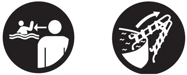
Supervise, Supervise, Supervise
STAY AWAY FROM DRAINS AND SUCTIONS FITTINGS

- Children, especially children under five years, are at high risk of drowning.
- Remove or secure ladder when not in use.
- Closely watch children who are in or near this pool.
- Diving or jumping may result in a broken neck, paralysis, permanent injury, or death.
- If the drain or suction outlet cover is missing or broken, your hair, body, and jewelry can get sucked into the drain. You could be held underwater and drown! Do not use the pool if the drain or suction outlet cover is missing or broken.
- Empty pool or prevent access when not in use. Store the empty pool in such a way that it does not collect water from rain or any other source.
Prevent Young Children From Drowning:
- Keep unsupervised children from accessing the pool by installing fencing or approved barriers around all sides of the pool. State or local laws or codes may require fencing or other approved barriers. Check state or local laws and codes before setting up the pool. Refer to the list of barrier recommendations and guidelines as described in CPSC Publication No. 362. “Safety Barrier Guideline for Home Pools” found at www.poolsafely.gov.
- Drowning occurs silently and quickly. Assign an adult to supervise pool and wear provided water watcher tag.
- Keep children in your direct sight when they are in or near pool. Pool presents a drowning hazard even during filling and draining of the pool. Maintain constant supervision of children and do not remove any safety barriers until the pool is completely empty and stowed away.
- When searching for a missing child, check the pool first, even if you think your child is in the house.
Prevent Young Children From Gaining Access to Pool:
- Toddlers can climb ladder and get into pool. Before leaving pool area, remove ladder or other means of access, and safely store away from pool.
- When leaving the pool, remove floats and toys from the pool that might attract a child.
- Position furniture (for example, tables, chairs) away from pool so that children cannot climb on it to gain access to the pool.
- If a filter pump is included with the pool, locate pumps and filters in such a way that children cannot climb on them and gain access to the pool.
Electrocution Risk:
- Keep all electrical lines, radios, speakers and other electrical appliances away from the pool.
- Do not place pool near or under overhead electrical lines.
Suction Risk:
- If a filter pump is included with the pool, the replacement pump shall never exceed the maximum flow rate marked on the suction fitting.
Be Prepared to Respond to an Emergency:
- Keep a working phone and a list of emergency numbers near the pool.
- Become certified in cardiopulmonary resuscitation (CPR) so you can respond to an emergency. In the event of an emergency, immediate use of CPR can make a life-saving difference.
Barriers for Residential Swimming Pool Guidelines:
An outdoor swimming pool, including an inground, aboveground, or on-ground pool, hot tub, or spa, should be provided with a barrier which complies with the following:
- The top of the barrier should be at least 48 inches above grade measured on the side of the barrier which faces away from the swimming pool. The maximum vertical clearance between the grade and the bottom of the barrier should be 4 inches measured on the side of the barrier which faces away from the swimming pool. Where the top of the pool structure is above grade, such as an aboveground pool, the barrier may be at ground level, such as the pool structure, or mounted on top of the pool structure. Where the barrier is mounted on top of the pool structure, the maximum vertical clearance between the top of the pool structure and the bottom of the barrier should be 4 inches.
- Openings in the barrier should not allow passage of a 4-inch diameter sphere.
- Solid barriers, which do not have openings, such as a masonry or stone wall, should not contain indentations or protrusions except for normal construction tolerances and tooled masonry joints.
- Where the barrier is composed of horizontal and vertical members and the distance between the tops of the horizontal members is less than 45 inches, the horizontal members should be located on the swimming pool side of the fence. Spacing between vertical members should not exceed 1-3/4 inches in width. Where there are decorative cutouts, spacing within the cutouts should not exceed 1-3/4 inches in width.
- Where the barrier is composed of horizontal and vertical members and the distance between the tops of the horizontal members is 45 inches or more, spacing between vertical members should not exceed 4 inches. Where there are decorative cutouts, spacing within the cutouts should not exceed 1-3/4 inches in width.
- Maximum mesh size for chain link fences should not exceed 1-1/4 inch square unless the fence is provided with slats fastened at the top or the bottom which reduce the openings to no more than 1-3/4 inches.
- Where the barrier is composed of diagonal members, such as a lattice fence, the maximum opening formed by the diagonal members should be no more than 1-3/4 inches.
- Access gates to the pool should comply with Section I, Paragraphs 1 through 7, and should be equipped to accommodate a locking device. Pedestrian access gates should open outward, away from the pool, and should be self-closing and have a self-latching device. Gates other than pedestrian access gates should have a self-latching device. Where the release mechanism of the self-latching device is located less than 54 inches from the bottom of the gate, (a) the release mechanism should be located on the pool side of the gate at least 3 inches below the top of the gate and (b) the gate and barrier should have no opening greater than 1/2 inch within 18 inches of the release mechanism.
- Where a wall of a dwelling serves as part of the barrier, one of the following should apply:
(a) All doors with direct access to the pool through that wall should be equipped with an alarm that produces an audible warning when the door and its screen, if present, are opened. The alarm should sound continuously for a minimum of 30 seconds within 7 seconds after the door is opened. Alarms should meet the requirements of UL 2017 General-Purpose Signaling Devices and Systems, Section 77. The alarm should have a minimum sound pressure rating of 85 dBA at 10 feet and the sound of the alarm should be distinctive from other household sounds, such as smoke alarms, telephones, and doorbells. The alarm should automatically reset under all conditions. The alarm should be equipped with manual means, such as touchpads or switches, to temporarily deactivate the alarm for a single opening of the door from either direction. Such deactivation should last for no more than 15 seconds. The deactivation touchpads or switches should be located at least 54 inches above the threshold of the door.
(b) The pool should be equipped with a power safety cover that complies with ASTM F1346-91 listed below.
(c) Other means of protection, such as self-closing doors with self-latching devices, are acceptable so long as the degree of protection afforded is not less than the protection afforded by (a) or (b) described above. - Where an aboveground pool structure is used as a barrier or where the barrier is mounted on top of the pool structure, and the means of access is a ladder or steps, then (a) the ladder to the pool or steps should be capable of being secured, locked or removed to prevent access, or (b) the ladder or steps should be surrounded by a barrier. When the ladder or steps are secured, locked, or removed, any opening created should not allow the passage of a 4-inch diameter sphere. Barriers should be located so as to prohibit permanent structures, equipment or similar objects from being used to climb the barriers.
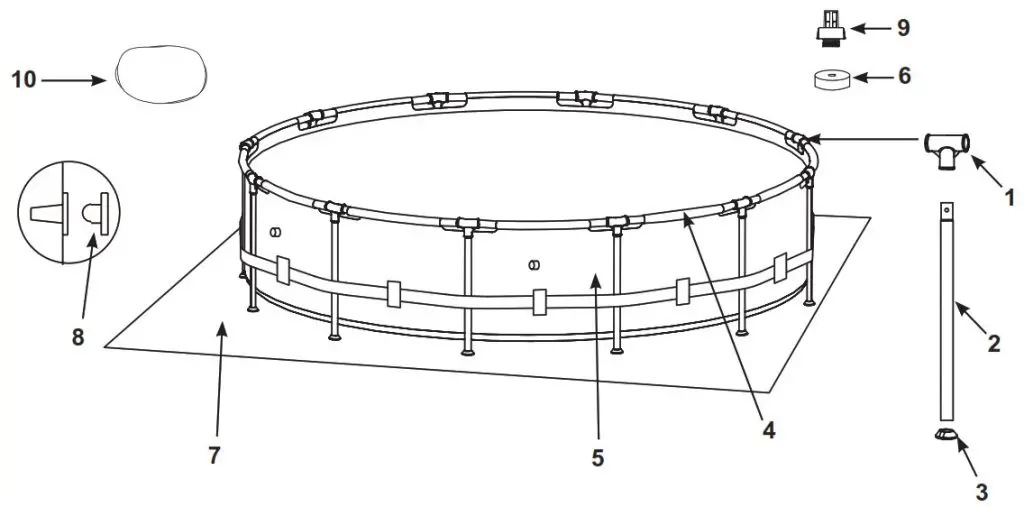
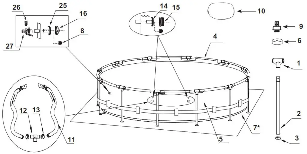
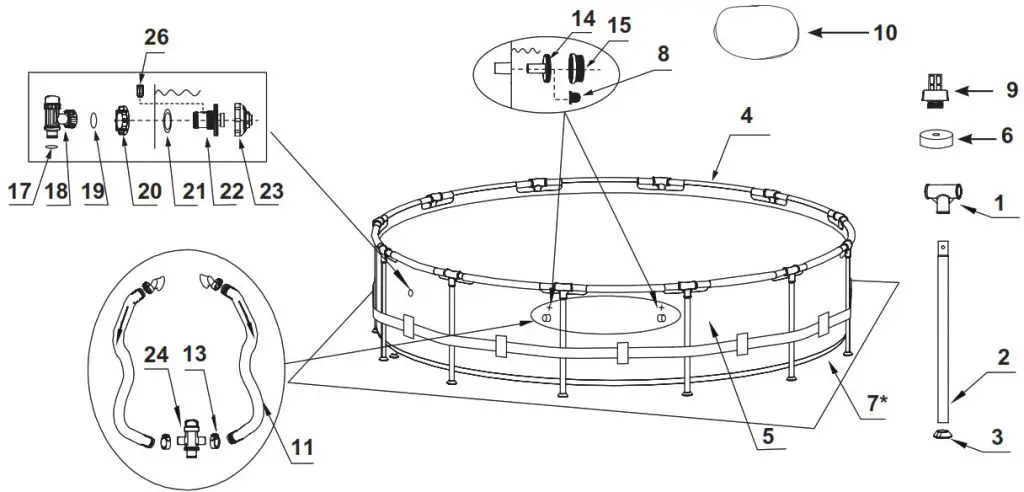
PARTS REFERENCE
Before assembling your product, please take a few minutes to check the contents and become familiar with all the parts.
For Pools with Dual Suction Outlets Configuration:
In order to comply with the requirement of the Virginia Grahame Baker Act (for USA and Canada), your pool is designed with dual suction outlets and one inlet fittings. Overview of the dual suction outlets configuration is as follow:
16′ (488 cm) and below
18′ (549 cm) and above
NOTE: Drawings for illustration purpose only. Actual product may vary. Not to scale.
| REF NO. |
DESCRIPTION | POOL SIZE & QUANTITIES | |||||||
| 10′ (305cm) |
12′ (366cm) |
13′ (396cm) |
14′ (427cm) |
15′ (457cm) |
16′ (488cm) |
18′ (549cm) |
24′ (732cm) |
||
| 1 | T – JOINT | 10 | 12 | 13 | 14 | 15 | 16 | 18 | 24 |
| 2 | VERTICAL LEG | 10 | 12 | 13 | 14 | 15 | 16 | 18 | 24 |
| 3 | LEG CAP | 10 | 12 | 13 | 14 | 15 | 16 | 18 | 24 |
| 4 | HORIZONTAL BEAM | 10 | 12 | 13 | 14 | 15 | 16 | 18 | 24 |
| 5 | POOL LINER (DRAIN VALVE CAP INCLUDED) | 1 | 1 | 1 | 1 | 1 | 1 | 1 | 1 |
| 6 | DRAIN VALVE CAP | 1 | 1 | 1 | 1 | 1 | 1 | 2 | 2 |
| 7. | GROUND CLOTH | – | – | – | – | 1 | 1 | 1 | 1 |
| 8 | STRAINER HOLE PLUG | 3 | 3 | 3 | 3 | 3 | 3 | 2 | 2 |
| 9 | DRAIN CONNECTOR | 1 | 1 | 1 | 1 | 1 | 1 | 1 | 1 |
| 10′ | POOL COVER | – | – | 1 | 1 | 1 | 1 | 1 | 1 |
| 11 | HOSE | 2 | 2 | 2 | 2 | 2 | 2 | 2 | 2 |
| 12 | HOSE T-JOINT | 1 | 1 | 1 | 1 | 1 | 1 | – | – |
| 13 | HOSE CLAMP | 8 | 8 | 8 | 8 | 8 | 8 | 4 | 4 |
| 14 | STRAINER CONNECTOR | 2 | 2 | 2 | 2 | 2 | 2 | 2 | 2 |
| 15 | STRAINER GRID | 2 | 2 | 2 | 2 | 2 | 2 | 2 | 2 |
| 16 | POOL INLET JET NOZZLE | 1 | 1 | 1 | 1 | 1 | 1 | – | – |
| 17 | HOSE 0-RING | – | – | – | – | – | – | 1 | 1 |
| 18 | PLUNGER VALVE (HOSE 0-RING & STEP WASHER INCLUDED) | – | – | – | – | – | – | 1 | 1 |
| 19 | STEP WASHER | – | – | – | – | – | – | 1 | 1 |
| 20 | STRAINER NUT | – | – | – | – | – | – | 1 | 1 |
| 21 | FLAT STRAINER RUBBER WASHER | – | – | – | – | — | 1 | 1 | |
| 22 | INLET THREADED AIR CONNECTOR + | – | – | – | – | – | – | ||
| 23 | ADJUSTABLE POOL INLET JET NOZZLE | .- | – | – | – | – | – | 1 | 1 |
| 24 | SPLIT HOSE PLUNGER VALVE | – | – | – | – | – | – | 1 | 1 |
| 25 | INLET STRAINER CONNECTOR | 1 | 1 | 1 | 1 | 1 | 1 | – | – |
| 26 | AIR JET VALVE | 1 | 1 | 1 | 1 | 1 | 1 | 1 | 1 |
| 27 | POOL INLET AIR ADAPTOR + | 1 | 1 | 1 | 1 | 1 | 1 | – | – |
| 28 | AIR JET VALVE CAP (NOT SHOWN) | 1 | 1 | 1 | 1 | 1 | 1 | 1 | 1 |
+ If applicable, depending on the size of the filter pump fitted with your pool, you must quote the model number shown on the filter pump housing to order the correct size of “Pool Inlet Air Adaptor” or “Inlet Threaded Air Connector” replacement part.
” * “: Optional.
| REF NO | DESCRIPTION | 10’ X 30” (305cm X 76cm |
12’ X 30” (366cm X 76cm) |
12’ X 33” (366cm X 84cm |
12’ X 36” (366cm X 91cm |
12’ X 39” (366cm X 99cm) |
13’ X 39” (396cm X 99cm) |
14 X 42” (427cm X 107cm) |
15’ X 33” (457cm X 84cm) SPARE PART NO. |
15’ X 36” (457cm X 91cm) |
15’ X 42” (457cm X 107cm) |
15’ X 48” (457cm X 122cm) |
16’ X 42” (488cm X 107cm |
18’ X 48” (549cm X 122cm) |
24’ X 52” (732cm X 132cm) |
| 1 | T – JOINT | 12798 | 12798 | 12798 | 12798 | 12798 | 12799 | 12799 | 12799 | 12799 | 12799 | 12799 | 12799 | 12800 | 12800 |
| 2 | VERTICAL LEG | 12810 | 12810 | 12811 | 12812 | 12813 | 12815 | 12816 | 12817 | 12337 | 12816 | 12818 | 12816 | 12819 | 12820 |
| 3 | LEG CAP | 10309 | 10309 | 10309 | 10309 | 10309 | 12138 | 12138 | 12138 | 12138 | 12138 | 12138 | 12138 | 12139 | 12139 |
| 4 | HORIZONTAL BEAM | 12807 | 12807 | 12807 | 12807 | 12807 | 12808 | 12808 | 12808 | 12808 | 12808 | 12808 | 12808 | 12809 | 12809 |
| 5 | POOL LINER (DRAIN VALVE CAP INCLUDED) DRAIN VALVE CAP | 10095E | 10096E | 12883E | 12884E | 12885E | 12887E | 12888E | 10097E | 12890E | 12891E | 10098E | 12892E | 10099E | 12894E |
| 6 | GROUND CLOTH | 10649 | 10649 | 10649 | 10649 | 10649 | 10649 | 10649 | 10649 | 10649 | 11044 | 11044 | 11044 | 11044 | 11044 |
| 7 | STRAINER HOLE PLUG | – | – | – | – | – | – | – | 18932 | 18932 | 18932 | 18932 | 18927 | 18933 | 18935 |
| 8 | DRAIN CONNECTOR | 10127 | 10127 | 10127 | 10127 | 10127 | 10127 | 10127 | 10127 | 10127 | 10127 | 10127 | 10127 | 10127 | 10127 |
| 9 | POOL COVER | 10184 | 10184 | 10184 | 10184 | 10184 | 10184 | 10184 | 10184 | 10184 | 10184 | 10184 | 10184 | 10184 | 10184 |
| 10 | HOSE | – | – | – | – | – | 11142 | 11054 | 18901 | 18901 | 18901 | 18901 | 10754 | 18937 | 18929 |
| 11 | HOSE T-JOINT | 11873 | 11873 | 11873 | 11873 | 11873 | 11873 | 11873 | 11873 | 11873 | 11873 | 11873 | 11873 | 11873 | 11873 |
| 12 | HOSE CLAMP | 11871 | 11871 | 11871 | 11871 | 11871 | 11871 | 11871 | 11871 | 11871 | 11871 | 11871 | 11871 | – | – |
| 13 | STRAINER CONNECTOR | 11489 | 11489 | 11489 | 11489 | 11489 | 11489 | 11489 | 11489 | 11489 | 11489 | 11489 | 11489 | 10122 | 10122 |
| 14 | STRAINER GRID | 11070 | 11070 | 11070 | 11070 | 11070 | 11070 | 11070 | 11070 | 11070 | 11070 | 11070 | 11070 | 11070 | 11070 |
| 15 | POOL INLET JET NOZZLE | 11072 | 11072 | 11072 | 11072 | 11072 | 11072 | 11072 | 11072 | 11072 | 11072 | 11072 | 11072 | 11072 | 11072 |
| 16 | HOSE O-RING | 12364 | 12364 | 12364 | 12364 | 12364 | 12364 | 12364 | 12364 | 12364 | 12364 | 12364 | 12364 | – | – |
| 17 | PLUNGER VALVE (HOSE O-RING | – | – | – | – | – | – | – | – | – | – | – | – | 10262 | 10262 |
| 18 | & STEP WASHER INCLUDED) | – | – | – | – | – | – | – | – | – | – | – | – | 10747 | 10747 |
| 19 | STEP WASHER | – | – | – | – | – | – | – | – | – | – | – | – | 10745 | 10745 |
| 20 | STRAINER NUT | – | – | – | – | – | – | – | – | – | – | – | – | 10256 | 10256 |
| 21 | FLAT STRAINER RUBBER WASHER | – | – | – | – | – | – | – | – | – | – | – | – | 10255 | 10255 |
| 22 | INLET THREADED AIR CONNECTOR + | – | – | – | – | – | – | – | – | – | – | – | – | 12371 | 12371 |
| 23 | ADJUSTABLE POOL INLET JET NOZZLE | – | – | – | – | – | – | – | – | – | – | – | – | 12372 | 12372 |
| 24 | SPLIT HOSE PLUNGER VALVE | – | – | – | – | – | – | – | – | – | – | – | – | 12369 | 12369 |
| 25 | 1-1/4” INLET STRAINER CONNECTOR | 12365 | 12365 | 12365 | 12365 | 12365 | 12365 | 12365 | 12365 | 12365 | 12365 | 12365 | 12365 | 11872 | 11872 |
| 26 | AIR JET VALVE | 12363 | 12363 | 12363 | 12363 | 12363 | 12363 | 12363 | 12363 | 12363 | 12363 | 12363 | 12363 | – | – |
| 27 | POOL INLET AIR ADAPTOR + | 12366 | 12366 | 12366 | 12366 | 12366 | 12366 | 12366 | 12366 | 12366 | 12366 | 12366 | 12366 | – | – |
| 12367 | 12367 | 12367 | 12367 | 12367 | 12367 | 12367 | 12367 | 12367 | 12367 | 12367 | 12367 | 12373 | 12373 | ||
| 12368 | 12368 | 12368 | 12368 | 12368 | 12368 | 12368 | 12368 | 12368 | 12368 | 12368 | 12368 | – | – | ||
| 28 | AIR JET VALVE CAP (NOT SHOWN) | 12373 | 12373 | 12373 | 12373 | 12373 | 12373 | 12373 | 12373 | 12373 | 12373 | 12373 | 12373 | 12373 | 12373 |
Before assembling your product, please take a few minutes to check the contents
and become familiar with all the parts.
16’ (488 cm) and below
18’ (549 cm) and above
NOTE: Drawings for illustration purpose only. Actual product may vary. Not to scale.
| REF NO. |
DESCRIPTION | POOL SIZE & QUANTITIES | |||||||
| 10′ (305cm) |
12′ (366cm) |
POOL
13′ |
SIZE &
14′ |
QUANTITIES
15′ |
16′ (488cm) |
18′ (549cm) |
24′ (732cm) |
||
| 1 | T – JOINT | 10 | 12 | 13 | 14 | 15 | 16 | 18 | 24 |
| 2 | VERTICAL LEG | 10 | 12 | 13 | 14 | 15 | 16 | 18 | 24 |
| 3 | LEG CAP | 10 | 12 | 13 | 14 | 15 | 16 | 18 | 24 |
| 4 | HORIZONTAL BEAM | 10 | 12 | 13 | 14 | 15 | 16 | 18 | 24 |
| 5 | POOL LINER (DRAIN VALVE CAP INCLUDED) | 1 | 1 | 1 | 1 | 1 | 1 | 1 | 1 |
| 6 | DRAIN VALVE CAP | 1 | 1 | 1 | 1 | 1 | 1 | 2 | 2 |
| 7 | GROUND CLOTH (OPTIONAL) | – | – | – | – | 1 | 1 | 1 | 1 |
| 8 | STRAINER HOLE PLUG (OPTIONAL, WITH 1 EXTRA) | 3 | 3 | 3 | 3 | 3 | 3 | – | |
| 9 | DRAIN CONNECTOR | 1 | 1 | 1 | 1 | 1 | 1 | 1 | 1 |
| 10 | POOL COVER (OPTIONAL) | – | 1 | 1 | 1 | 1 | 1 | 1 | |
| REF NO. |
DESCRIPTION | 10′ X 30″ (305cm X 76cm) |
17 X 30″ (366cm X 76cm) |
17 X 33″ (366cm X 84cm) |
17 X 36″ (366cm X 91cm) |
12′ X 39″ (366cm X 99cm) |
13′ X 39″ (396cm X 99cm) |
14 X 42″ (427cm X 107cm) |
| SPARE PART NO. | ||||||||
| 1 | T – JOINT | 12798 | 12798 | 12798 | 12798 | 12798 | 12799 | 12799 |
| 2 | VERTICAL LEG | 12810 | 12810 | 12811 | 12812 | 12813 | 12815 | 12816 |
| 3 | LEG CAP | 10309 | 10309 | 10309 | 10309 | 10309 | 12138 | 12138 |
| 4 | HORIZONTAL BEAM | 12807 | 12807 | 12807 | 12807 | 12807 | 12808 | 12808 |
| 5 | POOL LINER (DRAIN VALVE CAP INCLUDED) | 10095 | 10096 | 12883 | 12884 | 12885 | 12887 | 12888 |
| 6 | DRAIN VALVE CAP | 10649 | 10649 | 10649 | 10649 | 10649 | 10649 | 10649 |
| 7 | GROUND CLOTH (OPTIONAL) | – | – | – | ||||
| 8 | STRAINER HOLE PLUG (WITH 1 EXTRA) | 10127 | 10127 | 10127 | 10127 | 10127 | 10127 | 10127 |
| 9 | DRAIN CONNECTOR | 10184 | 10184 | 10184 | 10184 | 10184 | 10184 | 10184 |
| 10 | POOL COVER (OPTIONAL) | – | – | 11142 | 11054 | |||
| REF
NO. |
DESCRIPTION | 15X33″ (457cm X 84cm) |
15′ X 36″ (457cm X 91cm) |
15’X42″ (457cm X 107cm) |
15’X48″ (457cm X 122cm) |
16. X 42″ (488cm X 107cm) |
16’X48″ (488cm X 122cm) |
18′ X 41 (549cm X 122cm) |
24′ X 52″ (732cm X 132cm) |
| SPARE PART NO. | |||||||||
| 1 | T – JOINT | 12799 | 12799 | 12799 | 12799 | 12799 | 12799 | 12800 | 12800 |
| 2 | VERTICAL LEG | 12817 | 12337 | 12816 | 12818 | 12816 | 12818 | 12819 | 12820 |
| 3 | LEG CAP | 12138 | 12138 | 12138 | 12138 | 12138 | 12138 | 12139 | 12139 |
| 4 | HORIZONTAL BEAM | 12808 | 12808 | 12808 | 12808 | 12808 | 12808 | 12809 | 12809 |
| 5 | POOL LINER (DRAIN VALVE CAP INCLUDED) | 10097 | 12890 | 12891 | 10098 | 12892 | 12893 | 10099 | 12894 |
| 6 | DRAIN VALVE CAP | 10649 | 10649 | 11044 | 11044 | 11044 | 11044 | 11044 | 11044 |
| 7 | GROUND CLOTH (OPTIONAL) | 18932 | 18932 | 18932 | 18932 | 18927 | 18927 | 18933 | 18935 |
| 8 | STRAINER HOLE PLUG (WITH 1 EXTRA) | 10127 | 10127 | 10127 | 10127 | 10127 | 10127 | – | |
| 9 | DRAIN CONNECTOR | 10184 | 10184 | 10184 | 10184 | 10184 | 10184 | 10184 | 10184 |
| 10 | POOL COVER (OPTIONAL) | 18901 | 18901 | 18901 | 18901 | 10754 | 10754 | 18937 | 18929 |
POOL SETUP
IMPORTANT SITE SELECTION AND GROUND PREPARATION INFORMATION
WARNING
- The pool location must allow you to secure all doors, windows, and safety barriers to prevent unauthorized, unintentional or unsupervised pool entry.
- Install a safety barrier that will eliminate access to the pool for young children and pets.
- Failure to set up the pool on flat, level, compact ground and to assemble and fill with water in accordance with the following instructions could result in the pool’s collapse or the possibility that a person lounging in the pool could be swept out/ejected, resulting in serious injury or property damage.
- Risk of electric shock: connect the filter pump only to a grounding-type receptacle protected by a ground-fault circuit interrupter (GFCI). To reduce the risk of an electrical shock, do not use extension cords, timers, plug adapters or converter plugs to connect the pump to an electrical supply. Always provide a properly located outlet. Locate the cord where it cannot be damaged by lawnmowers, hedge trimmers, and other equipment. See the filter pump manual for additional warnings and instructions.
- Risk of serious injury: do not attempt to assemble pool in high wind conditions.
Select an outdoor location for the pool with the following requirements in mind:
- The area where the pool is to be set up must be absolutely flat and level. Do not set up the pool on a slope or inclined surface.
- The ground surface must be compacted and firm enough to withstand the pressure and weight of a fully set up pool. Do not set up the pool on mud, sand, soft or loose soil conditions.
- Do not set up the pool on a deck, balcony, or platform, which may collapse under the weight of the filled pool.
- The pool requires at least 4 feet of space all around the pool from objects that a child could climb on to gain access to the pool.
- The grass under the pool will be damaged. Splash out chlorinated pool water could damage the surrounding vegetation.
- Above ground storable pools shall be located at a minimum distance of 6 ft (1.83 meters) from any receptacle, and all 125-volt 15- and 20-ampere receptacles located within 20 ft (6.0 meters) of the pool shall be protected by a ground fault circuit interrupter (GFCI), where distances are by measuring the shortest path the supply cord of an appliance connected to the receptacle would follow without piercing a floor, wall, ceiling, doorway with hinged or sliding door, window opening, or another effective permanent barrier.
- Eliminate all aggressive grasses first. Certain types of grass such as St. Augustine and Bermuda may grow through the liner. Grass growing through the liner it is not a manufacturing defect and is not covered under warranty.
- The area shall facilitate drainage of the pool water after each use and/or for long-term pool storage.
IMPORTANT
Before allowing anyone to use the pool, hold a family meeting. Establish a set of rules that include, at a minimum, the important safety rules and general aquatic safety information in this manual. Review these rules on a regular basis and with all users of the pool, including guests. The installer of the vinyl liner shall affix on the original or replacement liner, or on the pool structure, all safety signs in accordance with the manufacturer’s instructions. The safety signs shall be placed above the waterline.
You may have purchased this pool with the Intex Krystal Clear™ filter pump. The pump has its own separate set of installation instructions. First assemble your pool unit and then set up the filter pump.
Estimated assembly time 30-60 minutes. (Note the assembly time is only approximate and individual assembly experience may vary.)
1. Liner preparation
• Find a flat, level location that is free and clear of stones, branches or other sharp objects that may puncture the pool liner or cause injury.
• Open the carton containing the liner, joints, legs, etc., very carefully as this carton can be used to store the pool during the winter months or when not in use.
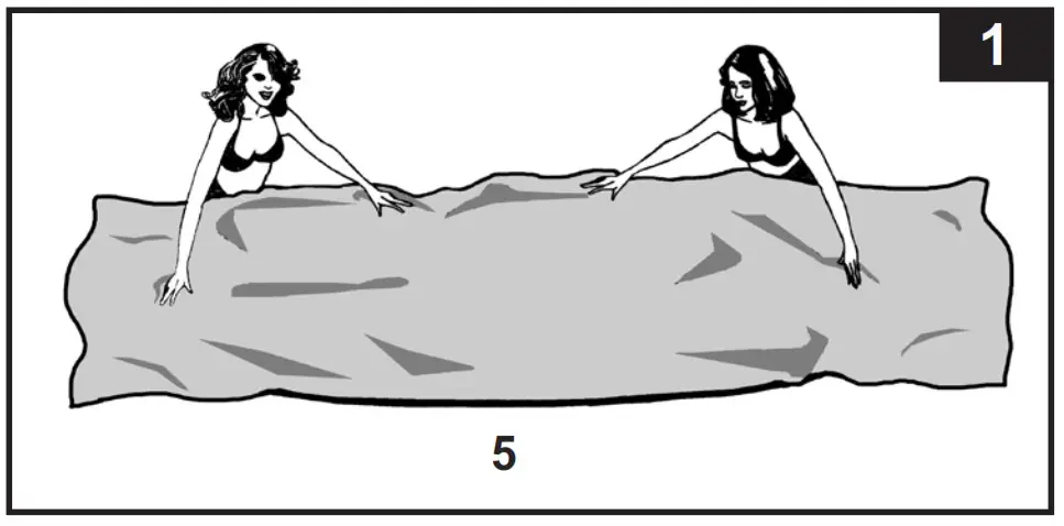
• Take out the ground cloth (7) (optional) and spread it over the cleared area. Then take out the liner (5) and spread it out over the ground cloth, with the drain valve directed towards the draining area. Place the drain valve away from the house. Allow the sun to warm up the liner before inserting the beams (4) into the sleeve openings. IMPORTANT: Always set up the pool unit with at least 2 persons. Do not drag the liner across the ground as this can cause liner damage and pool leakage (see drawing 1).
 • During the setup of this pool liner, point the hose connections or openings in the direction of the electric power source. The outer edge of the pool should be within reach of the pump’s electrical connection.
2. Horizontal beams assembly
• The frame pool’s legs (2) and beams (4) fall into two groups. The larger diameters are the horizontal beams that are slid (pushed) into the sleeve openings at the top of the liner. The smaller diameters are the vertical legs. Both these legs and beams fit into the T-joints (1).
NOTE: Sprinkle some talcum powder over the horizontal beams before sliding them into the pool liner sleeve. This will make the removal of the beams from the liner easier during the disassembly of the pool.
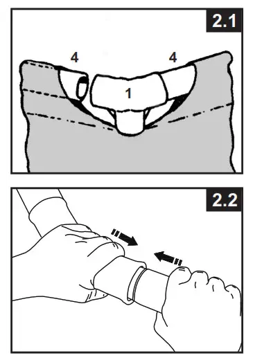
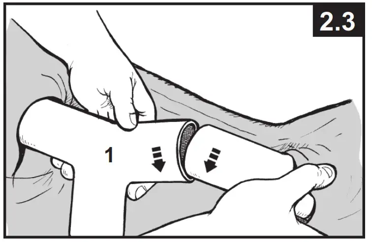
• Starting at any location, but always working in the same direction, push the horizontal beam into the sleeve. Once the beam is centered take one of the T-joints and attach the joint to one end of the beam. Push the beam firmly into the T-joint. Repeat this procedure in a circular fashion until all the beams and joints have been connected (see drawings 2.1 & 2.2).
NOTE: It’s important to start from one location and work in the same direction until the last attachment. Do not start from multiple locations as this will make the connections difficult for the last few beams and joints.
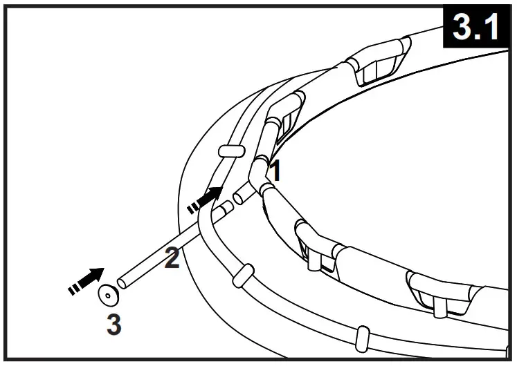
The last joint connection may be difficult to complete. You can do it though if you first simultaneously raise the last joint and beam about 2 inches (5 cm). Now insert the beam into the joint while lowering the pieces into position. The beam will easily slide into the joint (see drawing 2.3).
Ensure that the last joint is fully connected before proceeding to connect the legs.
3. Vertical legs assembly
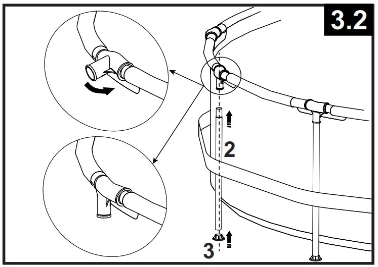
• Attach the leg’s end cap (3) to the bottom of each leg (2) first. With the beams and T-joints assembly resting on the ground, slide one vertical leg into the belt loop located in the middle of the pool liner and insert the top of the leg into the bottom of the T-joint (1) (see drawing 3.1). Continue the process with all the vertical legs.
• Lift the beams assembly and make sure all the legs are in a vertical position (see drawing 3.2). Push all the T-joints downward to ensure they are firmly connected to the legs.
• Pull gently, in an outward direction, the bottom of the leg making sure the leg is vertical and perpendicular to the level ground.
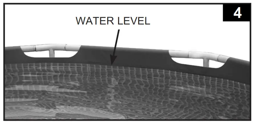
4. Filling of the pool
- The following applies to pool liners with hose connectors (16’ (488 cm) & below pools). If the pool was purchased without a filter pump, insert the strainer hole plugs (8) into the black filter pump outlets. Do this from the inside of the pool so that water will not run out when filling it. If the pool was purchased with a filter pump, read the Krystal Clear™ Filter Pump Manual first and then proceed to the next installation step.
- Before filling the pool with water, ensure that the drain plug inside the pool is closed and that the drain cap on the outside is screwed on tightly. Fill the pool with no more than 1 inch (2.5 cm) of water. Check to see whether the water is level.
IMPORTANT: If the water in the pool flows to one side, the pool is not completely level. Setting up the pool on the unlevel ground will cause the pool to tilt resulting in the sidewall material bulging and a potential collapse of the pool. If the pool is not completely level, you must drain the pool, level the area or move the pool to a different area that is level, and re-fill the pool, following the above directions. - Smooth out the bottom liner wrinkles (from inside the pool) by pushing out where the pool floor and poolsides meet. Or, (from the outside pool) reach under the side of the pool, grasp the pool floor and pull in an outward direction. If the ground cloth is causing the wrinkles, have 2 people pull from opposite sides to remove all wrinkles. Use the properly assembled pool ladder when entering or exiting the pool during this process. Also, make sure all the legs are vertical and perpendicular to the ground.
- Fill the pool with water up to just below the sleeve line (see drawing 4).
5. Posting aquatic safety signs
Select a highly visible area near the pool to post the Danger No Diving or Jumping sign included later in this manual.
GENERAL AQUATIC SAFETY
Water recreation is both fun and therapeutic. However, it involves inherent risks of injury and death. To reduce your risk of injury, read and follow all product, package and package insert warnings and instructions. Remember, however, that product warnings, instructions, and safety guidelines cover some common risks of water recreation, but do not cover all risks and dangers.
Assign an adult to be responsible for watching children in the pool. Give this person a “water watcher” tag and ask that they wear it the entire time they are in charge of supervising children in the pool. If they need to leave for any reason, ask this person to pass the “water watcher” tag and the supervision responsibility to another adult.
For additional safeguards, also familiarize yourself with the following general guidelines as well as guidelines provided by nationally recognized Safety Organizations:
- Demand constant supervision. A competent adult should be appointed as a “lifeguard” or water watcher, especially when children are in and around the pool. • Learn to swim.
- Take the time to learn CPR and first aid.
- Instruct anyone who is supervising pool users about potential pool hazards and about the use of protective devices such as locked doors, barriers, etc.
- Instruct all pool users, including children what to do in case of an emergency.
- Always use common sense and good judgment when enjoying any water activity.
- Supervise, supervise, supervise.
For additional information on safety, please visit
- The Association of Pool and Spa Professionals: The Sensible Way to Enjoy Your Aboveground/Onground Swimming Pool www.nspi.org
- American Academy of Pediatrics: Pool Safety for Children www.aap.org
- Red Cross www.redcross.org
- Safe Kids www.safekids.org
- Home Safety Council: Safety Guide www.homesafetycouncil.org
- Toy Industry Association: Toy Safety www.toy-tia.org
SAFETY IN YOUR POOL
Safe swimming depends on constant attention to the rules. You may also wish to copy and laminate the sign for protection from the elements. You can also download and print additional copies of the warning sign and water watcher tags at www.intexcorp.com.
POOL MAINTENANCE and CHEMICALS
WARNING
REMEMBER TO
- Protect all pool occupants from possible water-related illnesses by keeping the pool water clean and sanitized. Do not swallow the pool water. Always practice good
hygiene. - Keep your pool clean and clear. The pool floor must be visible at all times from the outside barrier of the pool.
- Keep children away from pool covers to avoid entanglement, drowning, or another serious injury.
Water maintenance
The maintenance of a proper water balance through the appropriate use of sanitizers is the single most important factor in maximizing the life and appearance of the liner as well as ensuring clean, healthy, and safe water. Proper technique is important for water testing and treating the pool water. See your pool professional for chemical, test kits, and testing procedures. Be sure to read and follow the written instructions from the chemical manufacturer.
1. Never let chlorine come in contact with the liner if it is not completely dissolved. Dissolve granular or tablet chlorine first in a bucket of water, then add it to the pool water. Likewise, with liquid chlorine; mix it immediately and thoroughly with the pool water.
2. Never mix chemicals together. Add the chemicals to the pool water separately. Thoroughly dissolve each chemical before adding another one to the water.
3. An Intex pool skimmer and an Intex pool vacuum are available to assist in maintaining clean pool water. See your pool dealer for these pool accessories.
4. Do not use a pressure washer to clean the pool.
POOL MAINTENANCE and DRAINAGE
WARNING
ALWAYS FOLLOW THE CHEMICAL MANUFACTURER’S DIRECTIONS AND THE HEALTH AND HAZARD WARNINGS.
Do not add chemicals if the pool is occupied. This can cause skin or eye irritation. Concentrated chlorine solutions can damage the pool liner. In no event is Intex Recreation Corp., Intex Development Co. Ltd., their related companies, authorized agents and service centers, retailers, or employees liable to the buyer or any other party for costs associated with the loss of pool water, chemicals, or water damage.
Keep spare filter cartridges on hand. Replace cartridges every two weeks. We recommend the use of a Krystal Clear™ Intex Filter Pump with all of our above-ground pools.
To purchase an Intex Filter Pump or other accessories see your local retailer, visit our website or call the Intex Consumer Services Department listed in the separate “Authorized Service Centers” sheet and have your Visa or Mastercard ready.
EXCESSIVE RAIN: To avoid damage to the pool and overfilling, immediately drain rainwater that causes the water level to be higher than the maximum.
How to Drain Your Pool and Long Term Storage
- Check local regulations for specific directions regarding disposal of swimming pool water.
- Check to make sure that the drain plug inside the pool is plugged in place.
- Remove the cap from the drain valve on the outside pool wall.
- Attach the female end of the garden hose to the drain connector (9).
- Place the other end of the hose in an area where the water can be safely drained away from the house and other nearby structures.
- Attach the drain connector to the drain valve. NOTE: The drain connector will push the drain plug open inside the pool and water will start to drain immediately.
- When the water stops draining, start lifting the pool from the side opposite the drain, leading any remaining water to the drain and emptying the pool completely.
- Disconnect hose and adapter when finished.
- Re-insert the drain plug-in drain valve on the inside of the pool for storage.
- Replace the drain cap on the outside of the pool.
- Reverse set-up instructions to disassemble the pool, and remove all connecting parts.
- Be sure that the pool and all parts are completely dry before storage. Air-dry the liner in the sun until completely dry before folding (see drawing 5). Sprinkle some talcum powder to prevent the vinyl from sticking together and to absorb any residual moisture.
- Create a square shape. Starting at one side, fold one-sixth of liner in on itself twice. Do the same on the opposite side (see drawings 6.1 & 6.2).
- Once you have created two opposing folded sides, simply fold one over the other like closing a book (see drawings 7.1 & 7.2).
- Fold the two long ends to the middle (see drawing 8).
- Fold one over the other like closing a book and finally compact the liner (see drawing 9).
- Store the liner and accessories in a dry, temperature-controlled, between 32 degrees Fahrenheit (0 degrees Celsius) and 104 degrees Fahrenheit (40 degrees Celsius), storage location.
- The original packing can be used for storage.

WINTER PREPARATIONS
Winterizing your Above Ground Pool
After usage, you can easily empty and store away your pool in a safe place. You must drain, disassemble and properly store the pool when the temperature drops below 41 degrees Fahrenheit (5 degrees Celsius) to prevent ice damage to the pool and related components. Ice damage can result in sudden liner failure or pool collapse. Also, see the section “How To Drain Your Pool’’. Should temperatures in your area not drop below 41 degrees Fahrenheit (5 degrees Celsius), and you choose to leave your pool out, prepare it as follows:
1. Clean the pool water thoroughly. If the type is an Easy Set Pool or an Oval Frame Pool, make sure that the top ring is properly inflated.
2. Remove the skimmer (if applicable) or any accessories attached to the threaded strainer connector. Replace strainer grid if necessary. Be sure all accessories parts are clean and completely dry before storage.
3. Plug the Inlet and Outlet fitting from the inside of the pool with the plug provided (sizes 16′ and below). Close the Inlet and Outlet Plunger Valve (sizes 17′ and above).
4. Remove the ladder (if applicable) and store it in a safe place. Be sure the ladder is completely dry before storage.
5. Remove the hoses that connect the pump and filter to the pool.
6. Add the appropriate chemicals for the winter period. Consult your local pool dealer as to which chemicals you should use and how to use them. This can vary greatly by region.
7. Cover pool with Intex Pool Cover. IMPORTANT NOTE: INTEX POOL COVER IS NOT A SAFETY COVER.
8. Clean and drain the pump, filter housing, and hoses. Remove and discard the old filter cartridge. Keep a spare cartridge for the next season.
9. Bring pump and filter parts indoors and store them in a safe and dry area, preferably between 32 degrees Fahrenheit (0 degrees Celsius) and 104 degrees Fahrenheit
(40 degrees Celsius).
TROUBLESHOOTING
| PROBLEM | DESCRIPTION | CAUSE | SOLUTION |
| ALGAE | Greenish water. Green or black spots on pool liner. Pool liner is slippery and/or has a bad odor. | Chlorine and pH level need adjustment. | Super chlorinate with shock treatment.Correct pH to your pool store’s recommended level. Vacuum pool bottom. Maintain proper chlorine level. |
| COLORED WATER | Water turns blue, brown, or black when first treated with chlorine. | Copper, iron or manganese in water being oxidized by the added chlorine. | Adjust pH to recommended level. Run filter until water is clear. Replace cartridge frequently. |
| FLOATING
MATTER IN WATER |
Water is cloudy or milky. | “Hard water” caused by a too high pH level. Chlorine content is low. Foreign matter in water. |
Correct the pH level. Check with your pool dealer for advice. Check for proper chlorine level. Clean or replace your filter cartridge. |
| CHRONIC LOW WATER LEVEL | Level is lower than on previous day. | Rip or hole in pool liner or hoses. | Repair with patch kit. Finger tighten all caps. Replace the hoses. |
| SEDIMENT ON POOL BOTTOM | Dirt or sand on pool floor. | Heavy use, getting in and out of pool. | Use Intex pool vacuum to clean bottom of pool. |
| SURFACE DEBRIS | Leaves, insects etc. | Pool too close to trees. | Use Intex pool skimmer. |
| PROBLEM | CAUSE | SOLUTION |
| POOL INLET AIR ADAPTOR LEAKING | Hose clamps are not well-fitted. | Tighten or reinstall hose clamps. |
| INLET TREADED AIR CONNECTOR LEAKING | Plunger valve not well-fitted. | Tighten or reinstall plunger valve |
| AIR JET VALVE LEAKING | Air jet valve is not tight and facing up. Air jet valve internal seal blocked. Air jet valve internal seal dirty. Air jet valve broken. |
Tighten air jet valve and make sure it’s facing up. Turn ON or plug in the pump and run for few seconds, then turn OFF or unplug, repeat 3 times. Remove air jet valve, flush dirt out with water and replace valve back. Replace a new air jet valve. |
LIMITED WARRANTY
Your Intex Pool has been manufactured using the highest quality materials and workmanship. All Intex products have been inspected and found free of defects prior to leaving the factory. This Limited Warranty applies to the Intex Pool only.
The provisions of this Limited Warranty apply only to the original purchaser and is not transferable. This Limited Warranty is valid for a period of 90 days from the date of the initial retail purchase. Keep your original sales receipt with this manual, as proof of purchase will be required and must accompany warranty claims or the Limited Warranty is invalid.
If a manufacturing defect is found within this 90-day period, please contact the appropriate Intex Service Center listed in the separate “Authorized Service Centers” sheet. The Service Center will determine the validity of the claim. If the Service Center directs you to return the product, please carefully package the product and send it with shipping and insurance prepaid to the Service Center. Upon receipt of the returned product, the Intex Service Center will inspect the item and determine the validity of the claim. If the provisions of this warranty cover the item, the item will be repaired or replaced at no charge.
Any and all disputes regarding the provisions of this Limited Warranty shall be brought before an informal dispute settlement board and unless and until the provisions of these paragraphs are carried forth, no civil action may be instituted. The methods and procedures of this settlement board shall be subject to the rules and regulations set forth by the Federal Trade Commission (F.T.C.). IMPLIED WARRANTIES ARE LIMITED TO THE TERMS OF THIS WARRANTY AND IN NO EVENT SHALL INTEX, THEIR AUTHORIZED AGENTS OR EMPLOYEES BE LIABLE TO THE BUYER OR ANY OTHER PARTY FOR DIRECT OR CONSEQUENTIAL DAMAGES OR LIABILITIES. Some states or jurisdictions do not allow the exclusion or limitation of incidental or consequential damages, so the above limitation or exclusion may not apply to you.
This Limited Warranty does not apply if the Intex product is subject to negligence, abnormal use or operation, accident, improper operation, improper maintenance or storage, or to damage by circumstances beyond Intex’s control, including but not limited to, punctures, tears, abrasions, ordinary wear and tear and damage caused by exposure to fire flood, freezing, rain, or other external environmental forces. This Limited Warranty applies only to those parts and components sold by Intex. The Limited Warranty does not cover unauthorized alterations, repairs, or disassembly by anyone other than Intex Service Center personnel.
DO NOT GO BACK TO THE PLACE OF PURCHASE FOR RETURN OR REPLACEMENT. IF YOU ARE MISSING PARTS OR NEED ASSISTANCE, PLEASE CALL US TOLL-FREE (FOR U.S. AND CANADIAN RESIDENTS): 1-800-234-6839 OR VISIT OUR WEBSITE: WWW.INTEXCORP.COM.
Proof of Purchase must accompany all returns or the warranty claim will be invalid.
SAVE THESE INSTRUCTIONS