
JBL Stadium 600 Amplifier

THANK YOU FOR YOUR PURCHASE
Your product has been designed to provide you the performance and ease of operation you expect from JBL. Take time to read this manual before operating or installing your amplifier. Keep it in your glove compartment along with the owner’s manual for your car. Put your amplifier sales receipt with other important documents in order to expedite warranty service if needed. This manual describes general installation guidelines and operation instructions. Please note that proper installation of mobile audio components requires qualified experience with mechanical and electrical procedures. If you do not have the knowledge and tools to perform this installation, we strongly recommend consulting an authorized JBL dealer about your installation options.
What’s in the box
- 1x amplifier
- 2x speaker-level input adapter
- 4x mounting screws
- 2x spare fuses
- 1x E.A.R.L ground terminal
- 3x self-tapping screws
- 1x remote bass controller and cable
- 1x owner’s manual
INSTALLATION AND WIRING
IMPORTANT: Disconnect the vehicle’s negative (-) battery terminal before beginning the installation.
- Wear protective eyewear when using tools.
- Choose a safe mounting location, away from moisture. Check clearances on both sides of the location. Be sure that screws will not puncture brake or fuel lines or wiring harnesses, and that wire routing will not interfere with vehicle operation. Use caution when drilling or cutting.
- When making electrical connections, make sure they are secure and properly insulated.
- To keep the amplifier cool, choose a location that provides enough air circulation, such as under a seat or in the trunk.
- Do not mount the amplifier with the heat sink facing downward, as this interferes with cooling.
- Mount the amplifier so that it will not be damaged by the feet of passengers or shifting cargo in the trunk, and so that it remains dry.
- Using the amplifier as a template, mark the locations of the holes on the mounting surface.
- Drill pilot holes in the mounting surface.
- Attach the amplifier to the mounting surface with the included screws.
NOTE: You may find it more convenient to make all of the connections to the amplifier before you permanently mount it.

Speaker Output Connectors
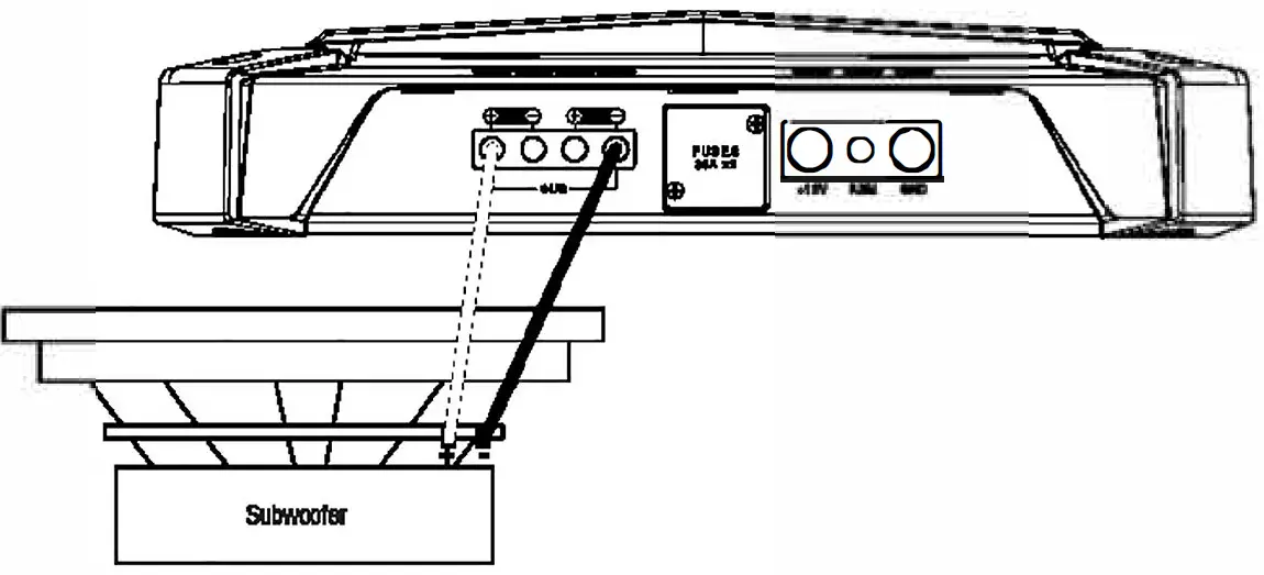
Connect the speakers to these terminals, observing proper polarity (connect each speaker’s positive(+) lead to the appropriate positive(+) terminal, and negative(-) lead to the appropriate negative (-) terminal. To power two subwoofers, connect one sub’s positive (+) and negative(-) leads to the positive and negative terminals on the left, and the other sub’s positive and negative leads to the positive and negative terminals on the right. The terminals are internally paralleled.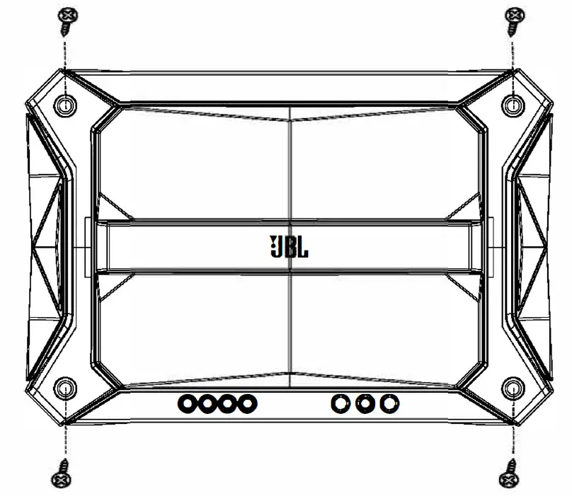 To power one sub, connect the positive wire from the single subwoofer to the left+ terminal, and the negative wire from the subwoofer to the right – terminal.
 NOTE: Minimum speaker impedance for subwoofer operation is 2 ohms.
Fuses
Replace fuses only with the same amperage: 35A.
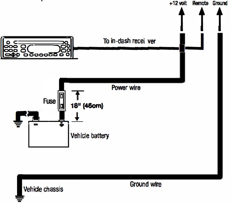
Power Input Connectors
• Power: Run 4-gauge power wire from the + 12V input to the positive terminal of the vehicle’s battery. Insert bare wire into the terminal on the amplifier, then tighten the setscrew with a Phillips screwdriver.
• Install an appropriate fuse holder and 1 OOA fuse within 18″ (457mm) of the battery. Install protective grommets when routing wires through the bulkhead or other sheet metal. Use larger-gauge wiring for longer runs.
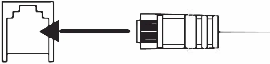
• Remote: The REM lead detects signal and instructs the amplifier to turn on/off. Connect a
• 20-gauge wire from the “Remote Out” lead of the source unit to the REM input between the + 12V and GND inputs.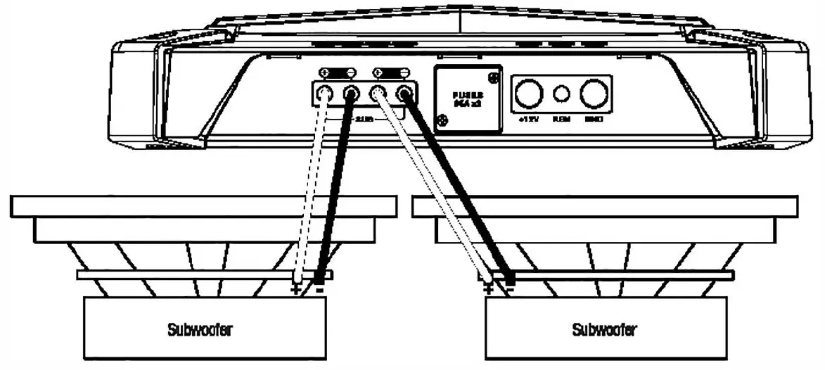
Remote bass level control
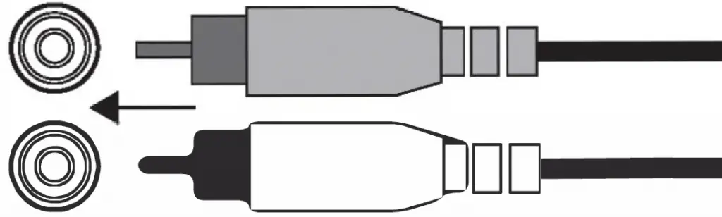
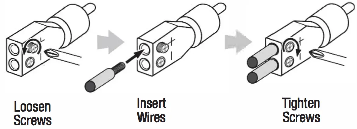
Line-level inputs (RCA)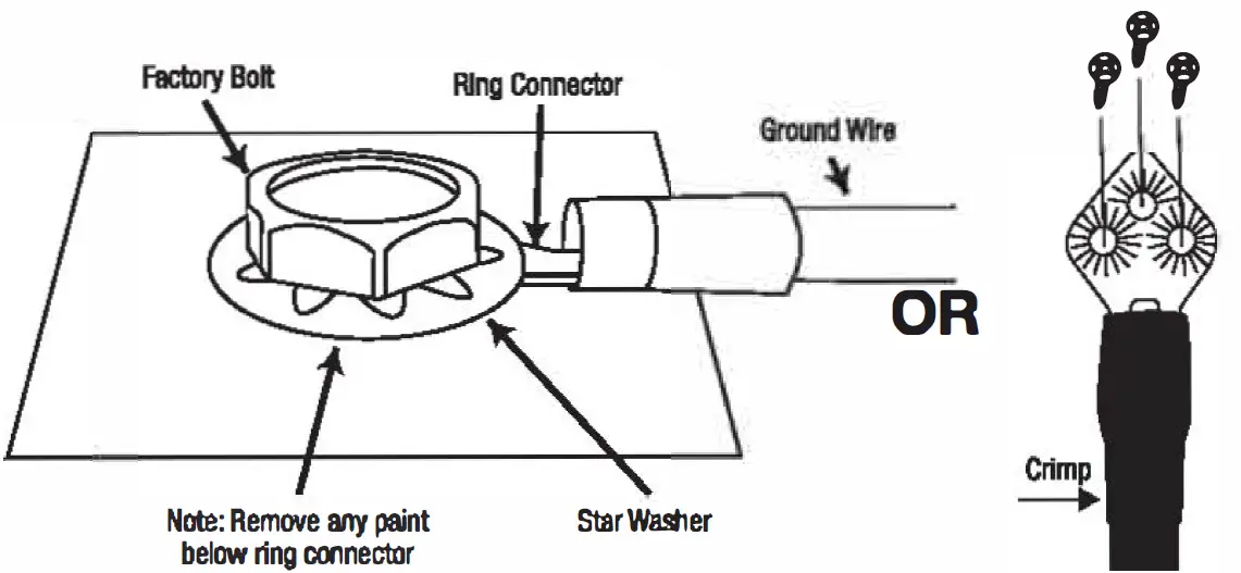
If your car audio system’s head unit does not have adapters line-level to outputs, connect use the the Stadium supplied amplifier’s bare inputs wire-to-RCA to audio either the system’s front or head the unit rear (splice speaker crimps outputs not of your included}. car set Use a screws small and Phillips insert the screwdriver speaker to wires loosen into the the adapter’s holes on the the back wires. of the adapter. Tighten the set screws to secure (+} Always terminal. terminal connect When and all the (-} wires (+} are speaker speaker wire connected, wire to to the the plug the adapter’s adapter’s adapt(-} into the Stadium amplifier’s preamp inputs.
Important: electronic Some filters factory that audio limit the system amount amplifiers of bass sent adversely to the affect system’s the Stadium smaller speakers. amplifier’s This performance. filtering will To get into the the most factory bass speaker possible, outputs splice that the are high-level connected wires to the reproduce system’s the largest most bass}. speakers (the ones designed to reproduce the most bass.
Input level
Select LO if providing signal to the amplifier with line-level connections.
Select Hl1 or Hl2 if using speaker-level connections.
Note: If you have connected your amplifier to factoryHl1 switch speaker to outputs “Hl2”. The and the “Hl2” audio position fails to includes play, a change circuit the designed to fool a factory audio system into “seeing” a speaker connected to its input. Important: “Hl2” should never be used when the amplifier is connected to a head unit’s line-level (RCA} outputs.
GAIN: Setting the input sensitivity
Adjusting the gain lets you match the input sensitivity of amp with the output of your receiver, and match the relative volume to the rest of your speakers.
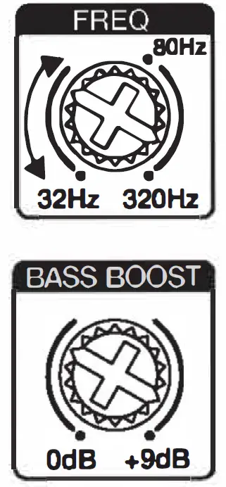
Crossover-filter frequency controls
Tum the dial to the left to lower the crossover point, and to the right to raise it. Adjust the crossover until your subwoofer plays only low-frequency information.
Bass boost
You can increase the bass output of your system up to +9 dB. Turn the dial to the right to increase the bass output.
Subwoofer phase selector
You can choose a phase of 0° or 180°. Play music with lots of bass and slide the switch back and forth. Choose the setting that gives you more bass. If you don’t detect any real difference, leave the dial at o.
Auto turn-on selector
If your stereo has no “Remote Out” lead, slide the “AUTO TURN ON” switch to “OW. This will allow the amp to turn on when it detects speaker-level audio signal.
Power/Protect indicators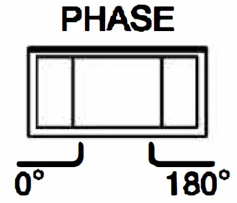
SPECIFICATIONS
- Operating voltage: 9-16 volts
- RMS power @ 4 ohms: 380W
- RMS power @ 2 ohms: 600W
- Total peak power: 1500W
- Fuse size: 2 x 35A
- High input maximum signal level: 20V
- High input maximum sensitivity: 2V
- Line input maximum signal level: 20V
- Line input maximum sensitivity: 0.2V
- Quiescent current draw: :.:1. 7 A
- Line-in signal-to-noise ratio (reference to 1 watt): 80dB
- Frequency response: 10 Hz – 320Hz @ -3dB
- Crossover filter: LPF 32Hz – 320Hz Variable 12dB/Oct
- Bass EQ: 70Hz Fix 0-9dB THD + N at rated power: :.:0.1 %
- Dimensions (H x W x D): 54.20mm x 179.60mm x 265.30mm
- Weight: 2.72kg
TROUBLESHOOTING
PROBLEM: No audio and POWER INDICATOR is off.
CAUSE and SOLUTION: No voltage at BATT+ and/or REM terminals, or bad or no ground connection. Check voltages at amplifier terminals with VOM.
PROBLEM: No audio and PROTECT INDICATOR flashes every 4 seconds.
CAUSE and SOLUTION: DC voltage on amplifier output. Amplifier may need service; see enclosed warranty card for service information.
PROBLEM: No audio and PROTECT and POWER INDICATORS flash.
CAUSE and SOLUTION: Voltage less than 9V on BATT+ connection. Check vehicle charging system.
PROBLEM: No audio and PROTECT INDICATOR is on.
CAUSE and SOLUTION: Amplifier is overheated. Make sure amplifier cooling is not blocked at mounting location.
Verify that speaker-system impedance is within specified limits. Or, there may be voltage greater than 16V (or less than 8.5V) on BATT+ connection. Check vehicle charging system.
PROBLEM: Amplifier fuse keeps blowing.
CAUSE and SOLUTION: The wiring is connected incorrectly or there is a short circuit. Review installation precautions and procedures. Check wiring connections.
PROBLEM: Distorted audio.
CAUSE and SOLUTION: Gain is not set properly. Check INPUT LEVEL setting. Check speaker wires for shorts or grounds. Amplifier or source unit may be defective.
PROBLEM: Distorted audio and PROTECT INDICATOR flashes.
CAUSE and SOLUTION: Short circuit in speaker or wire.
Remove speaker leads one at a time to locate shorted speaker or wire, and repair.
PROBLEM: Music lacks dynamics or “punch.”
CAUSE and SOLUTION: Speakers are not connected properly. Check speaker connections for proper polarity.
PROBLEM: Engine noise-whining or clicking-in system when the engine is on.
CAUSE and SOLUTION: Amplifier is picking up alternator noise. Turn down gain. Move audio cables away from power wires. Install an alternator noise filter on power line between battery and alternator. Check ground connections on the amplifier – a loose or improper ground is one of the main causes for noise.
HARMAN International Industries,
Incorporated 8500 Balboa Boulevard,
Northrid ge, CA 91329 USA
www.jbl.com
@2018 HARMAN International Industries, Incorporated. All rights reserved.
JBL is a trademark of HARMAN International Industries, Incorporated, registered in the United States and/or other countries. Features, specifications and appearance are subject to change without notice.
![]()