JENNAR Microwave Drawer and Trim Kit Installation Guide
Instructions
IMPORTANT:
Installer: Leave installation instructions with the homeowner.
Homeowner: Keep installation instructions for future reference.
IMPORTANT: Save for local electrical inspector’s use.
W11257634B
TINSKB267MRR0
MICROWAVE DRAWER SAFETY
Your safety and the safety of others are very important :
- We have provided many important safety messages in this manual and on your appliance, Always read and obey all safety messages.
 This is the safety alert symboL
- Th.s symbol alerts you to potential hazards that can kill or hurl you and others.
- All safety messages will follow the safety alert symbol and either the word “DANGER” or ‘WARNING.” These words words mean:
DANGER : You can be kited or seriously injured if you don’t immediately follow instructions.
WARNING : You can be killed or seriously injured if you don’t follow Instructions.
All safely messages will tell you what the potential hazard is. tell you how to reduce the chance of injury, and tell you what can happen if the instructions are not followed.
INSTALLATION REQUIREMENTS
These installation instructions cover different models. The appearance of your particular model may differ slightly from the illustrations in these Installation Instructions.
Tools and Parts
Gather the required tools and parts before starting installation. Read and follow the instructions provided with any tools listed here.
Tools needed :
- Tape measure
- #2 Phillips screwdriver
- Drill
- 1/8″ (3.17 mm) drill bit
- Marker or pencil
Parts supplied : The Microwave Drawer is preassembled.
- 1″ (2.5 cm) mounting screws (4)
- 1″ (2.5 cm) deflector screws (2)
- Flush mount deflector (1)
Optional Parts :
- 27″ (68.6 cm) Trim Kit (W11170223) for JMDFS24GS
- 27″ (68.6 cm) Trim Kit (W11264778) for JMDFS24HM
Verification needed :
- Installer must confirm presence of anti tip block. Refer to the anti-tip block section in the manual. Check local codes. Check existing electrical supply. See “Electrical Requirements”.
- It is required that all electrical connections be made by a licensed, qualified electrical installer.
Location Requirements
This product is suitable for use below electric or gas built-in ovens. This product is not suitable for use below cooktops.The Microwave Drawer may be located in a cabinet or below the counter, and/or below a built-in oven. Check the opening where the Microwave Drawer will be installed. The location must provide:
IMPORTANT: Observe all governing codes and ordinances.
- Wood cabinetry.
- Cutout opening that is plumb and square. See “Minimum Cutout Dimensions” in the “Minimum Dimensions” section.
- Cutout floor that is solid, level, and flush with bottom of cabinet cutout.
- Support for weight of at least 100 lbs (45.4 kg), which includes Microwave Drawer and items placed inside.
- Grounded electrical outlet. See the “Electrical Requirements”section.
- Minimum installation clearances for installation location. See the “Minimum Dimensions” section.
- Complete enclosure around the recessed portion of the Microwave Drawer
Minimum Dimensions
Minimum Wall Oven Combination Installation Clearances : For proper installation, the following minimum clearances must exist above and below the cutout opening.
NOTE: Upper oven must have heat deflector kit installed to direct exhaust away from microwave console (Refer to Wall Oven Manual for Deflector Kit Installation).
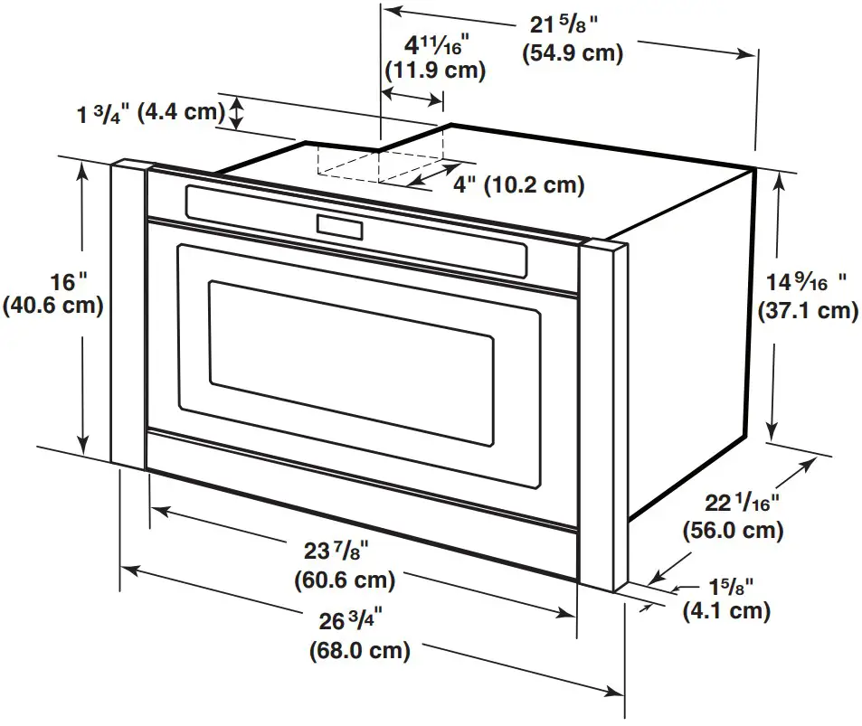
Product Dimensions :
- Dimension A: 24″ (61.0 cm) Product – 237 /8″ (60.6 cm) 30″ (76.2 cm) Product – 2915/16″ (76.0 cm)
- Dimension B: JMDFS24GS Model – 15 /8″ (4.1 cm) JMDFS30HL Model – 111/16″ (4.3 cm) JMDFS24HM Model – 13/4″ (4.4 cm) JMDFS30HM Model – 13 /4″ (4.4 cm).
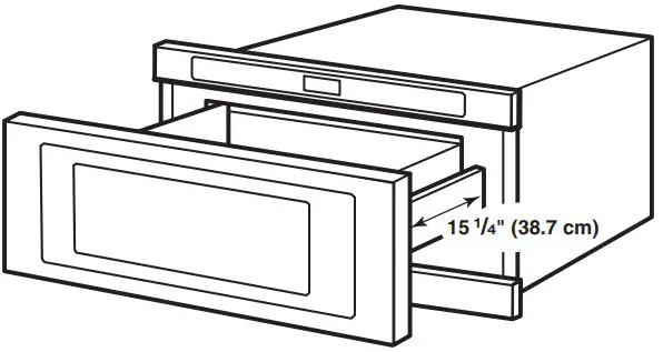
Optional 27″ (68.6 cm) Trim Kit:

The drawer opens 151 /4″ (38.7 cm).

Electrical Requirements
WARNING :  Electrical Shock Hazard
- Plug into a grounded 3 prong outlet.
- Do not remove ground prong.
- Do not use an adapter.
- Do not use an extension cord.
- Failure to follow these instructions can result in death, fire, or electrical shock.
IMPORTANT: Observe all governing codes and ordinances.
Required:
- A 120 V, 60 Hz, AC-only, 15 or 20 A electrical supply with a fuse or circuit breaker.
Recommended :
- A time-delay fuse or time-delay circuit breaker
- A separate circuit serving only this Microwave Drawer
GROUNDING INSTRUCTIONS
- For all cord connected appliances: The microwave oven must be grounded. In the event of an electrical short circuit, grounding reduces the risk of electric shock by providing an escape wire for the electric current. The microwave oven is equipped with a cord having a grounding wire with a grounding plug. The plug must be plugge.
WARNING:
- Improper use of the grounding plug can result in a risk of electric shock.
- Consult a qualified electrician or serviceman if the grounding instructions are not completely understood, or if doubt exists as to whether the microwave oven is properly grounded.
- Do not use an extension cord.
- If the power supply cord is too short, have a qualified electrician or serviceman install an outlet near the microwave oven.
- A short power supply cord is provided to reduce the risks resulting from becoming entangled in or tripping over a longer cord.
SAVE THESE INSTRUCTIONS
24″ (61.0 CM) AND 30″ (76.2 CM) STANDARD MOUNT
Cabinet Preparation
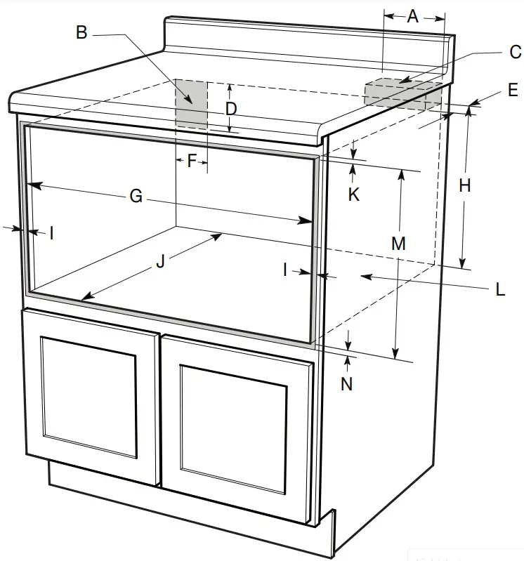
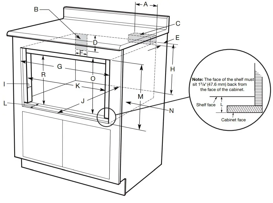
Cabinet Dimensions :
- A. 6″ (152.40 mm) minimum 16″ (406.40 mm) maximum
- B. Suggested electrical receptacle location
- C. Anti-Tip block
- D. 3″ (76.20 mm)
- E. 31 /2″ (88.90 mm)F. 4.5″ (114.30 mm)
- G. 221 /8″ (561.98 mm) opening
- H. 1413/16″ (376.24 mm) to bottom of Anti-Tip blockI. 24″ models:
- Allow 7/8″ (22.2 mm) overlap 30″ models: Allow 41 /16″ (103.19 mm) overlap
- J. 24″ (609.60 mm) minimum depth
- K. Allow 9/16″ (5.62 mm)
- L. Platform must support 100 lb (45.4 kg)
- M. 159 /16″ (395.27 mm) opening
- N. Allow 3/4″ (19.05 mm) overlap
- O. JMDFS24GS Model – 15 /8″ (41.28 mm) JMDFS30HL Model – 111/16″ (42.86 mm) JMDFS24HM Model – 13 /4″ (44.45 mm)
JMDFS30HM Model – 13/4″ (44.45 mm).
24″ (61.0 CM) AND 30″ (76.2 CM) FLUSH MOUNT
Cabinet Preparation
Cabinet Dimensions :
- A. 6″ (152.40 mm) minimum 16″ (406.40 mm) maximum
- B. Suggested electrical receptacle location
- C. Anti-Tip block
- D. 3″ (76.20 mm)
- E. 31 /2″ (88.90 mm)
- F. 4.5″ (114.30 mm)
- G. 221/8″ (561.98 mm) opening
- H. 1413/16″ (376.24 mm) to bottom of Anti-Tip blockI. Allow 23
- /8″ (60.5 mm) overlapJ. 24″ (609.60 mm) minimum depth
- K. Allow 9/16″ (5.62 mm)
- L. Platform must support 100 lb (45.4 kg)
- M. 159 /16″ (395.27 mm) opening
- N. Allow 3/4″ (19.05 mm) overlap
- O. JMDFS24GS Model – 15 /8″ (41.28 mm) JMDFS24HM Model – 13/4″ (44.45 mm).
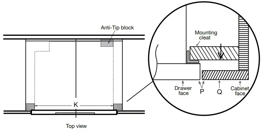
27″ (68.6 CM) TRIM KIT ACCESSORY STANDARD MOUNT (To be used with JMDFS24GS or JMDFS24HM)
Cabinet Preparation
Cabinet Dimensions :
- A. 6″ (152.40 mm) minimum 16″ (406.40 mm) maximum
- B. Suggested electrical receptacle location
- C. Anti-Tip blockD. 3″ (76.20 mm)
- E. 31 /2″ (88.90 mm)
- F. 4.5″ (114.30 mm)G. 271 /8″ (689 mm) minimum
- H. 1413/16″ (376.24 mm) to bottom of Anti-Tip block
- I. 1″ (25.40 mm) minimum
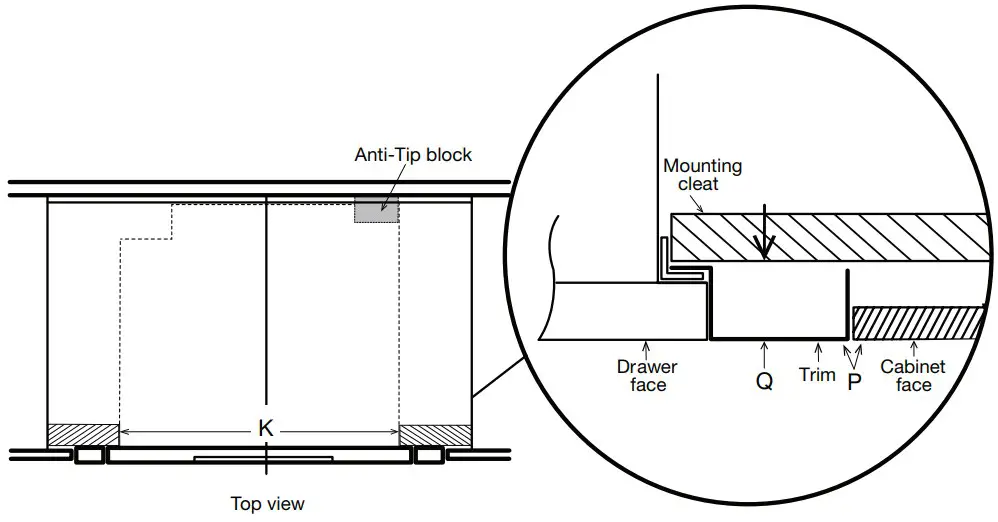
- J. 24″ (609.60 mm) minimum depthK. 221
- /8″ (561.98 mm) “mounting cleat tomounting cleat”
- L. 17 /8″ (47.62 mm)
- M. 167 /8″(428.62 mm) openingN. Platform must support 100 lb (45.4 kg)
- O. 161 /8″ (409.56 mm)
- P. 0″ (0 mm) = flush
- Q. JMDFS24GS Model – 15 /8″ (41.28 mm) JMDFS24HM Model – 13/4″ (44.45 mm) R. 159/16″ (395.3 mm).
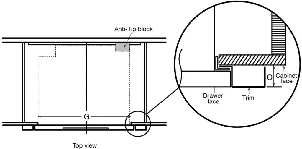
27″ (68.6 CM) TRIM KIT ACCESSORY FLUSH MOUNT (To be used with JMDFS24GS or JMDFS24HM)
Cabinet Preparation
Cabinet Dimensions :
- A. 6″ (152.40 mm) minimum 16″ (406.40 mm) maximum
- B. Suggested electrical receptacle locationC. Anti-Tip block
- D. 3″ (76.20 mm)
- E. 31 /2″ (88.90 mm)
- F. 4.5″ (114.30 mm)
- G. 271 /8″ (689 mm) minimum
- H. 1413/16″ (376.24 mm) to bottom of Anti-Tip block
- I. 1″ (25.40 mm) minimum
- J. 24″ (609.60 mm) minimum depth
- K. 221 /8″ (561.98 mm) “mounting cleat mounting cleat”
- L. 17/8″ (47.62 mm)M. 167 /8″(428.62 mm) opening
- N. Platform must support 100 lb (45.4 kg)O. 161 /8″ (409.56 mm) M
- P. 0″ (0 mm) = flush
- Q. JMDFS24GS Model – 15 /8″ (41.28 mm) MJMDFS24HM Model – 13/4″ (44.45 mm) R. 159 /16″ (395.3 mm)
INSTALLATION INSTRUCTIONS
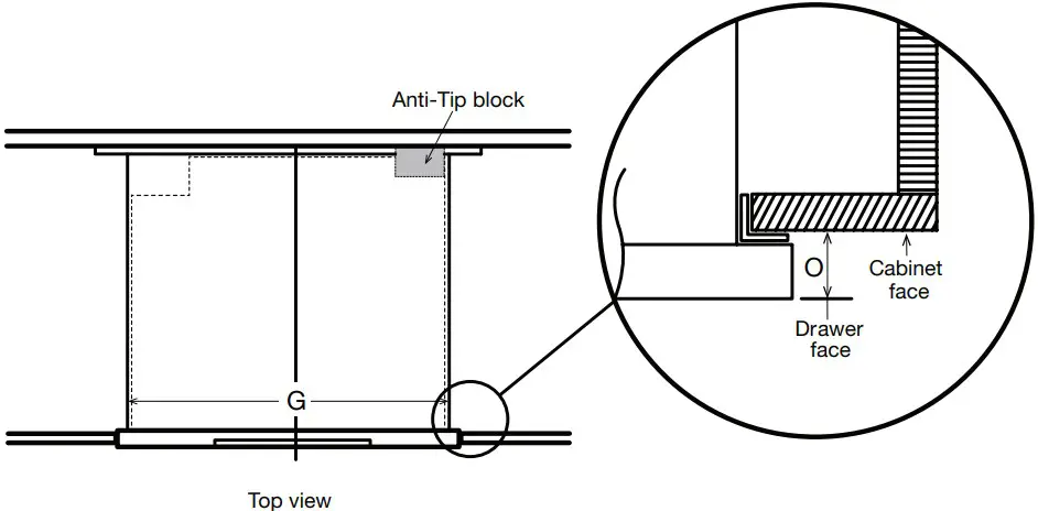
Install the Anti-Tip Block
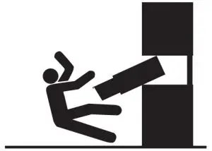
WARNING :  Crush Hazard
- Microwave drawer can tip and fall out of opening.
- Install anti-tip block to wall per installation instructions.
- Failure to do so can result in serious injury or burns.
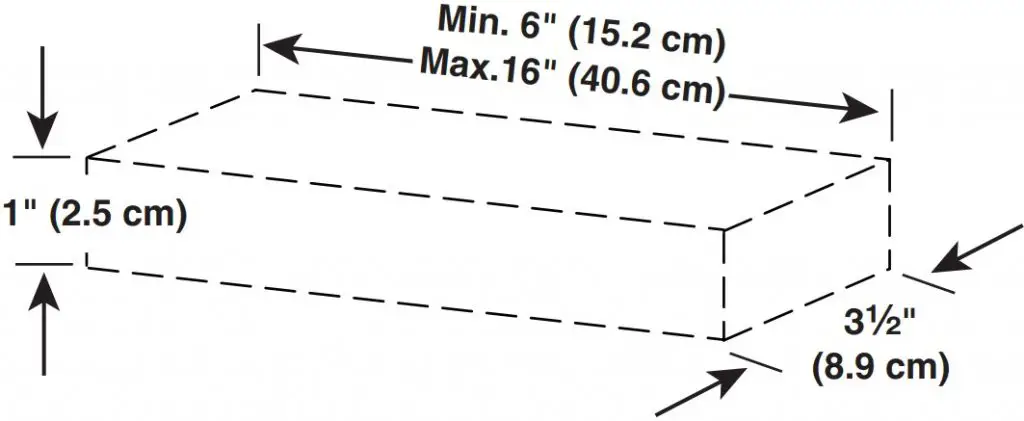
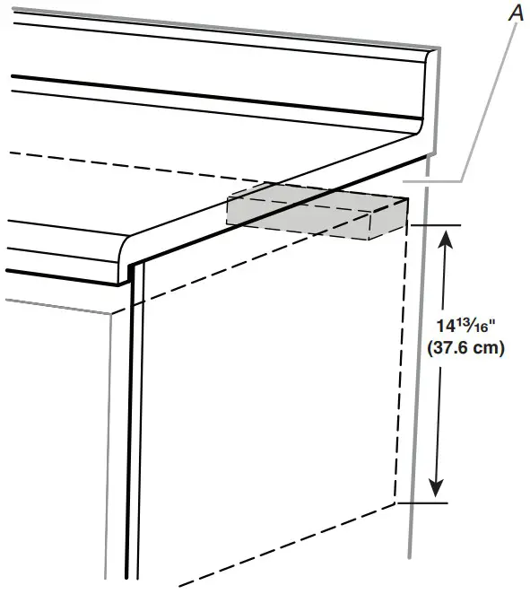
To reduce the risk of tipping of the drawer, the anti-tip block must be properly installed located 1413/16″ (37.6 cm) above the floor on which the Microwave Drawer will sit. If the Microwave Drawer is ever moved to a different location, the anti-tip block must also be moved and installed.
- Measure 1413/16″ (37.6 cm) from the cutout floor where the Microwave Drawer will sit and mark a line on the wall.
- Position the bottom of the anti-tip block on the line marked on the wall and attach the anti-tip block to the wall with screws. Make sure the screws are secured to wood or metal studs.
NOTES:
- The anti-tip block is required before installing the Microwave Oven Drawer.
- The anti-tip block is to be provided by the installer.
- When fastening, be sure that the screws do not penetrate electrical wiring or plumbing.
Anti-Tip Block Dimensions :
- A. Anti-tip block
Using sturdy wood screws (installer to provide), securely install the anti-tip block in the upper-right corner of the cutout, making sure the block is completely stable. The bottom of the block must be 1413/16″ (37.6 cm) from the cutout floor.
Install the Microwave Drawer
WARNING
Excessive Weight Hazard :
- Use two or more people to move and install microwave oven.
- Failure to do so can result in back or other injury.
- Empty Microwave Drawer of any loose contents.
- Using two or more people, slide Microwave Drawer all the way into the opening, and center the Microwave Drawer.
- Open the Microwave Drawer, and mark the four holes in the mounting flange.
NOTE: The screw holes in the mounting flange of both sides must be fully over the wood of the wall or cabinet. - Remove Microwave Drawer.
- Using 1/8″ (3.17 mm) drill, drill four pilot holes into the cabinet through the marks made in Step 3.
- Prepare the holes by installing a 1″ (2.5 cm) screw in and out of each pilot hole.
WARNING : Electrical Shock Hazard
- Plug into a grounded 3 prong outlet.
- Do not remove ground prong.
- Do not use an adapter.
- Do not use an extension cord.
- Failure to follow these instructions can result in death, fire, or electrical shock.
- With the Microwave Drawer near the opening, plug the Microwave Drawer into the grounded 3 prong outlet.
- Reinsert Microwave Drawer into the opening, open the drawer, and align holes in mounting flange with pilot holes in the cabinet.
- A. 1″ (2.5 cm) mounting screws (4)
- B. Mounting flange screw holes
- C. Mounting flange
- D. Optional 27″ (68.6 cm) Trim Kit Parts.
- Install four 1″ (2.5 cm) screws to secure the Microwave Drawer in place, then close the drawer.
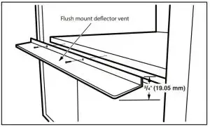
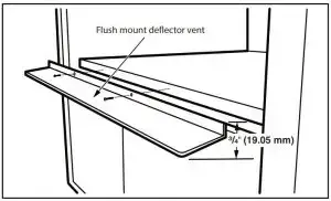
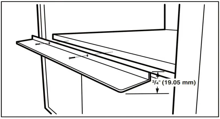
Install the Deflector Vent For Flush Installation
- Position deflector vent and mark holes.
- Pre-drill using a 1/8″ (3.17 mm) bit before mounting. Refer to illustrations below for vent positioning.
Shelf detail showing the deflector vent during installation
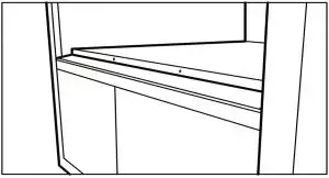
Shelf detail showing the deflector vent installed
WARNING : Electrical Shock Hazard- Plug into a grounded 3 prong outlet.
- Do not remove ground prong.
- Do not use an adapter.
- Do not use an extension cord.
- Failure to follow these instructions can result in death, fire, or electrical shock.
- Place the drawer adjacent to the wall or cabinet opening. Plug the power supply cord into the grounded 3 prong outlet.
- Guide the drawer into the prepared opening. Avoid contact with the sides of the cutout opening and also pinching the cord between the oven and the wall.
- Slide the drawer all the way back until the mounting flanges touch the cleats mounted in the cabinet opening.
- Open the drawer. Using the 4 holes on the drawer as a template, pre drill the cabinet using a 1/8″ (3.17 mm) bit. See illustration below.
- Secure the drawer with the 4 screws supplied.
Complete Installation
- Check the operation of Microwave Drawer by placing 1 cup (250 mL) of water in the Microwave Drawer and programming cook time of 1 minute at 100% power.
- If the Microwave Drawer does not operate:
- Check that a household fuse has blown, or a circuit breaker tripped. Replace the fuse or reset the circuit breaker. If the problem continues, call an electrician.
- Check that the power supply cord is plugged into a grounded 3 prong outlet. ee the Use and Care Guide for troubleshooting
information.
Installation is now complete : Save these Installation Instructions for future use.
ASSISTANCE
Call your authorized dealer or service center. When you call, you will need the microwave drawer model number and serial number, both of which can be found on the model and serial number plate.
If you need additional assistance, call us at our toll-free number or visit our website listed in the Use and Care Guide. To access the model and serial number plate, fully open the microwave drawer. The plate is located on a flat surface just beyond the back wall of the drawer.