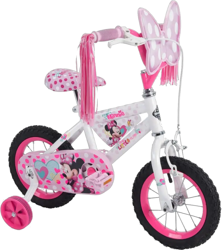
kmart 43076291 30cm Minnie Bike

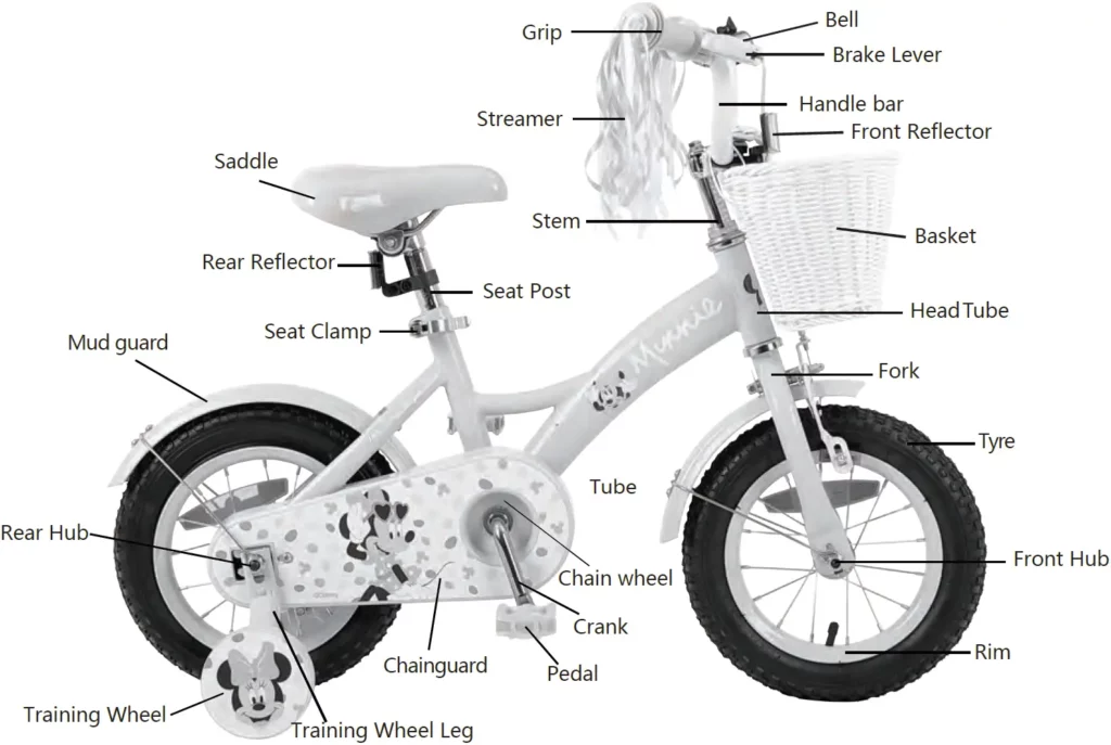
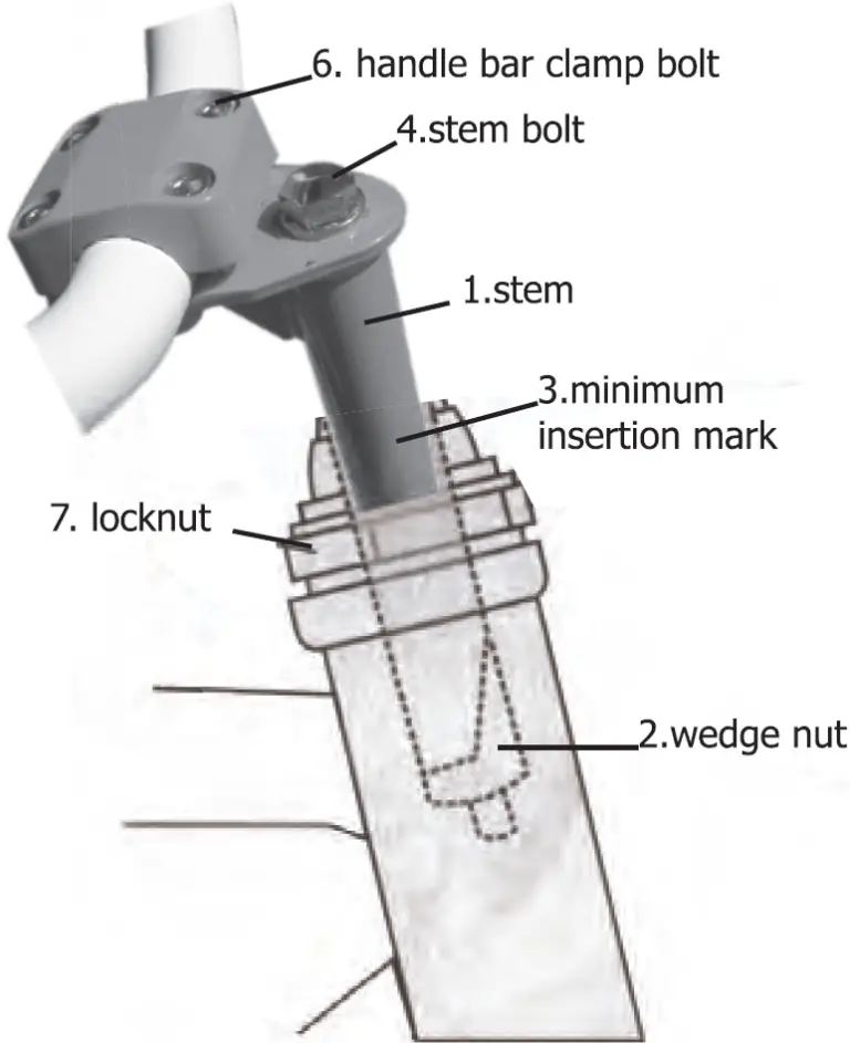
Name of Bicycle Parts
SAFETY PRECAUTIONS
Owner’s Safety Information and Responsibility
To reduce the risk of serious personal injury, you should read the instruction in this manual carefully.
There are WARNINGS throughout this manual, please follow all WARNING instructions.
WARNING: This bicycle is made to be ridden by one rider at a time for general transportation and recreational use. It is not made to withstand the abuse associated with stunting and jumping.
- The bicycle has been supplied partial assembled. It is owner’s responsibility to read and follow all the assembly and adjustment instructions exactly as written in this manual. Or you may ask a vehicle mechanic to assemble this bicycle.
- Know how to operate all standard and accessory equipment on the bicycle.
- Your bicycle conforms to relevant Australian Standards. Other local bicycle regulations may apply. Check with your retailer.
Wet Weather
- Use extra caution in wet weather.
- Avoid sudden braking.
- Apply brakes sooner in wet conditions, as stopping distance increase in weather.
- Slow overall riding pace and approach corner more carefully.
Night Riding
Avoid riding at night if possible, if you choose to ride at night:
- Purchase, install, and use a front and rear bicycle light.
- Make sure the reflectors of your bicycle are correctly positioned.
- Use a flashing rear light to improve visibility.
- Wear light-colored reflective clothing, such as a reflective vest and reflective bands for your arms and legs.
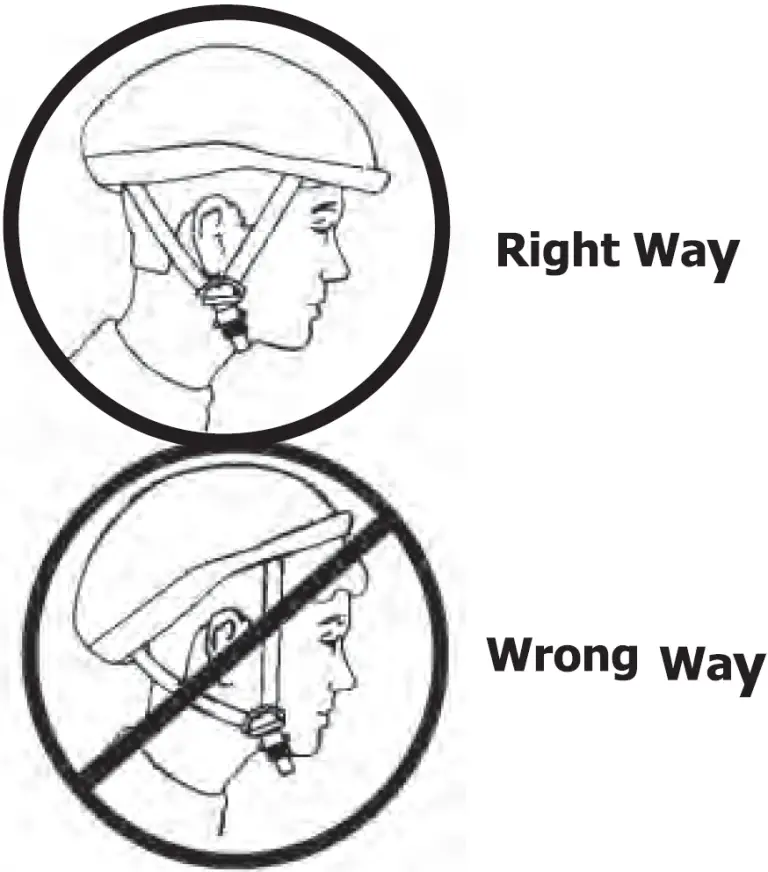
WARNING: Always wear a correctly fitted and fastened helmet when riding your bicycle.
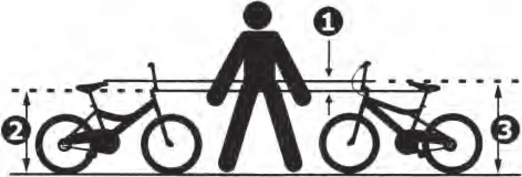
To determine the correct size of the bicycle for the rider.
- Straddle the assembled bicycle with feet shoulder with width apart and flat on the ground.
- There must be at least 25.4mm of clearance between the highest part of top tube (2) and the cloth of the rider. The minimum leg-length for the rider is the highest part of the top tube plus 25.4mm
- The rider must be able to easily reach and operate the brake levers (if so equipped).
- The seat position must be adjustable so that the feet of rider can reach the ground.
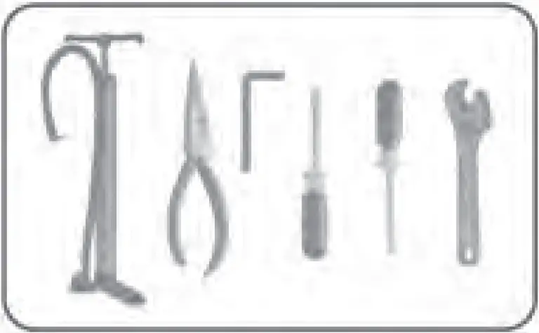
Tools Required (Not Included in the Packing)
Keep a Record of Your Bicycle
Each bicyle has a Serial Number stamped into the bottom of the frame. Write down this number to keep it for future reference. Take a color photograph of your bicycle, write the Serial number on the back of the photograph and keep it in a safe place. If you keep a record of the details of your bicycle it will greatly increase the possibility of getting it back should it be lost or stolen.
Remember the advice about LOCKING YOUR BICYCLE. A good quality lock is cheap insurance.
Bicycle Assembly
Front Wheel
Assemble the front wheel to the fork as shown
(Shown with bike sitting upside-down.)
WARNING: If you remove a brake shoe to install the front wheel, return it to the correct position as written in the “Brake and cable adjustment” Section.
- Make sure the tab of each security washer (2) is in the hole of the fork.
- Using the two axle nuts (3) with serrations, attach the front wheel.
WARNING: Do not use the nuts without serrations to attach the front wheel.
Put the wheel in the center of the fork and tighten both nut to the recommended torque of 25-28N.M.
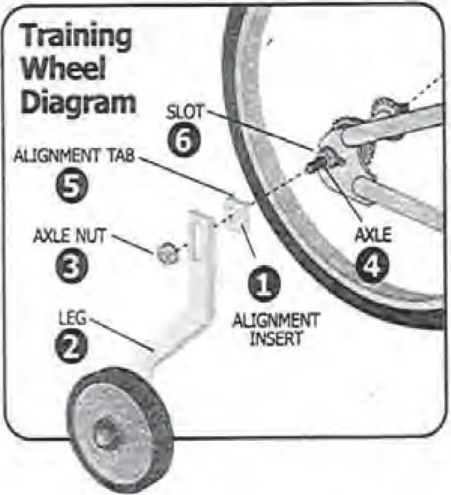
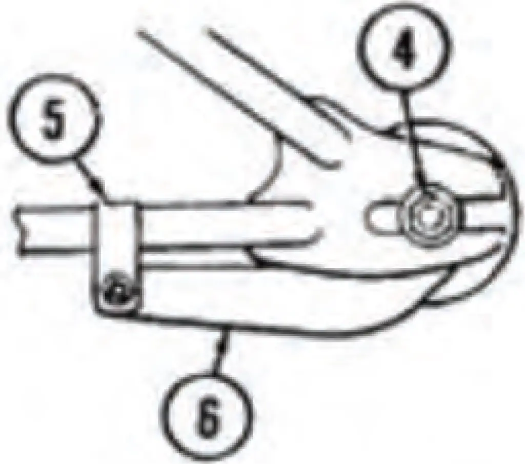
Training Wheel

Attach the legs to the bicycle frame:
- Put the alignment insert (1), a leg (2) and an axle nut (3) on each end of the rear wheel axle (4).
- Make sure the tab of the alignment insert (5), is to the rear of the axle and in the slot (6) of the frame.
- Make sure both training wheels are the same distance from the ground. Tighten the axle nuts securely.
WARNING: Before each ride, make sure both nuts are tight. Also make sure both training wheels are the same distance from the ground.
As your child’s ability and balance improve, you may raise or remove the training wheels.
To move the training wheels loosen the nut, slide the leg to the correct position, and retighten the nut.
To remove the training wheels, remove the nut, leg, and alignment insert.
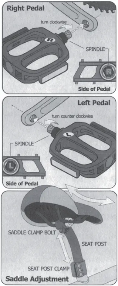
Install Pedals
All pedals have Lor R stamped on the threaded spindle of each pedal.
- Thread the pedal marked R clockwise into the right or chain wheel side of the crank
- Thread the pedal marked L counter-clockwise into the left side of the crank arm.
NOTE: Hand thread pedals into position without use of a wrench to ensure threads are not crossed threads. Damage to crank arm will result from crossed threads. When tightening with a wrench, make sure each spindle is firmly seated against the crank arm. If Jaws of wrench are too thick, they may prevent proper tightening of pedal spindle against crank arm.
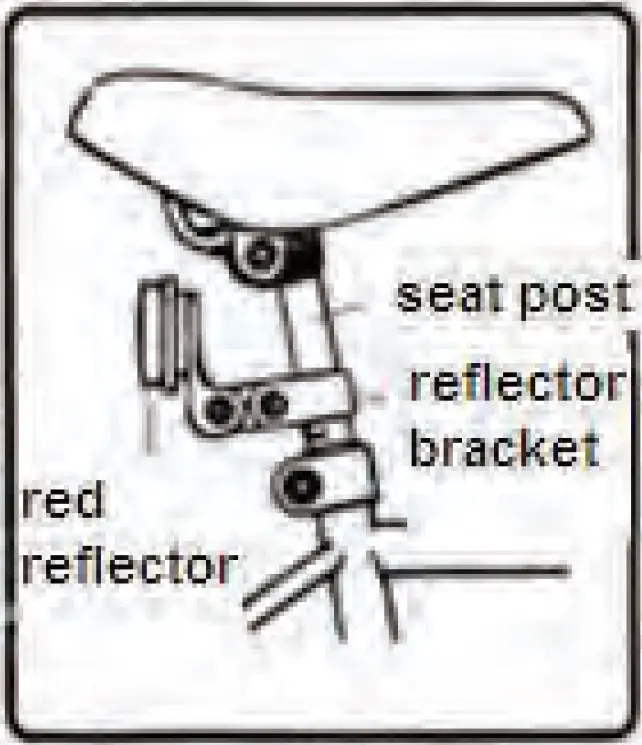
Install Saddle
- Insert the seat post into bicycle frame tube with small swaged end
Note: Seat post must be inserted at least to minimum insertion mark stamped on the lower part of the post. - Tighten the seat post clamp nut or quick release securely. Recommended torque is 12-17 N.M.
- Loosen saddle clamp nuts or quick release so saddle clamp will fit down fully onto top swaged end of seat
- Tighten seat post Recommended torque is 12-l7 N.M.
Note: If there is rear reflector, please install the rear reflector to the seat post before insert to the seat tube.
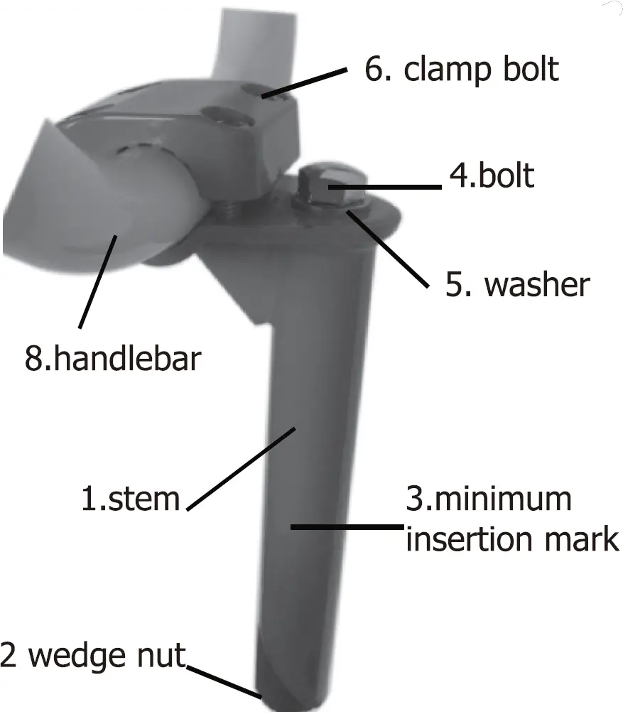
Handlebar and Stem
- Assemble the stem to the fork: if necessary, assemble the stem bolt, washer and wedge nut to the stem.
Turn the stem bolt only for revolutions and to the wedge nuts.
Find the stem towards the front of the bicycle and put it into the locknut.
Put the stamp at a comfortable height for the rider.
Make sure you can see the MIN-IN (minimum insertion) mark on the stem above the locknut.
Tighten the stem but just enough that the stem will not fall into the locknut. - Assemble the handlebar to the stem:
Put the handlebar into the stem but do not tighten the handlebar clamp at this time.
Align the stamp with the front wheel and tighten the stem bolt. - Assemble the brake lever to the handlebar. Loosen the clamp screw of each brake lever.
If necessary to move the handle bar to each side to install the brake levers foot the brake levers on the handle bar with the brake Lever for the rear brake on the right side of handlebar.
Do not tighten the clamp screw of the brake lever at this time. - Tighten stem bolt and handlebar clamp.
Put the handlebar in a comfortable position for the rider
Tighten the bolts of the handlebar clamp. If the handlebar clamp has more than one bolt, than tighten the bolts equally. - Test the tightness of the stem, straddle the front wheel and hold it between your legs.
Try to turn the front wheel by turning the handle bar. If the handlebar and stem turn without turning the front wheel realign the stamp with the front wheel.
Tighten the board tighter than you did before.
Do this test again until the handle park and stem do not turn without turning the wheel. - Test the tightness of the handlebar: hold the bicycle stationary and try to move on the ends of the handlebar forward or backward. If the handle bar moves, loosen bolts of handlebar clamps. Put the handlebar in the correct position.
Tighten the bolts of the handlebar clamp tighter than before if the handlebar clamp has more than one board tighten the boards equally.
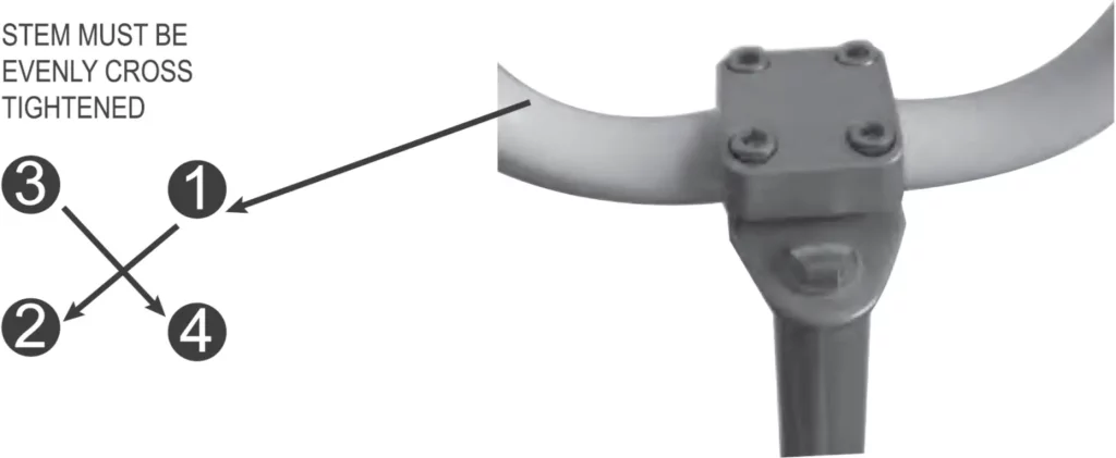
4-bolt-stem Instructions
Notice:
- Alight the stem in the steer tube so that the handlebar is perpendicular with the front wheel.
- Ensure the minimum insertion mark on the stem is not visible- beneath the top of the steer tube.
- Tighten the stem bolt enough so that stem will not rotate in the steer tube.
- Check the rotation with firm pressure.
Steps:
- Adjust and tighten the handlebar in the stem.
- Tight the 4 bolts in a cross pattern, and ensure they clamp evenly.
- Tighten the handlebar clam nuts enough so that handlebar will not rotate in the stem.
Check handlebar rotation with slight pressure.
Assemble the Accessories
- Assemble the crash pad
Assemble the pads in the correct location as shown. Attach with the sewn-in Velcro fasteners.
- Bell
The bell is attached to the handlebar. Adjust the bell ring to the comfortable place that is easily to be used when riding. - Front Reflector (Not Applicable)
Assemble the clear reflector to the front reflector bracket. - Rear Reflector (Not Applicable)
Assemble the red reflector onto the seat post. Make sure the red reflector is vertical, point toward the rear of the bicycle.

Repair and Service
Rear Wheel and chain Adjustment
Maintenance: The chain must be at the correct tightness. If too tight, the bicycle will be difficult to pedal. If too loose, the chain can come off the sprockets.
When the chain is at the correct tightness, you can pull it one-half inch away from a straightedge.
Adjust the tightness of the chain as follows: Loosen the axle nuts of the rear wheel.
Loosen the clamp on the brake arm, but do not remove the mt and screw from the clamp.

NOTE: Make sure that rear wheel is in the center of the bicycle frame.
Move the rear wheel forward or backward as necessary, until you can pull the chain on half inch away form a straightedge, Hold the wheel in the position and tighten the axle nuts to the recommended torque of 25-28 N.M.
TYRE REMOVAL
- Let the air out of the tyre by depressing the valve core (the little pin in the centre of the valve stem opening).
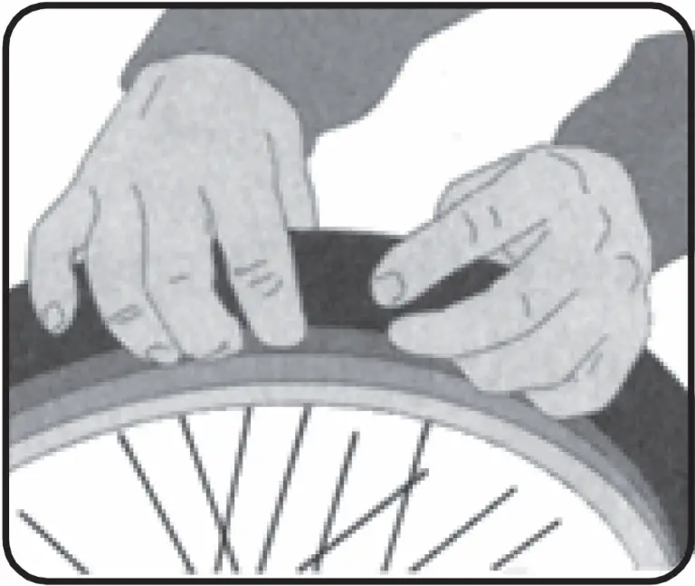
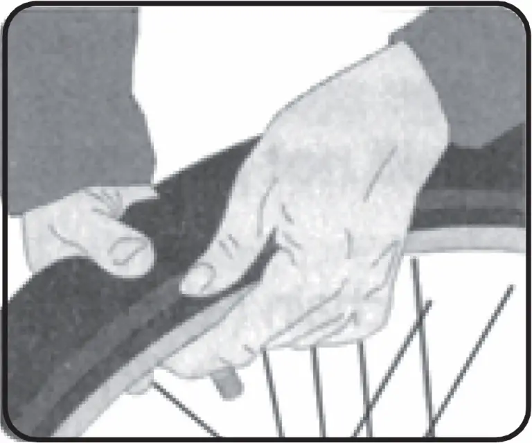
- Separate the tyre bead from the sides of the rim by pressing with your thumbs. Work your way around the tyre on both sides to be sure that the beads of the tyre are not sticking to the rim.
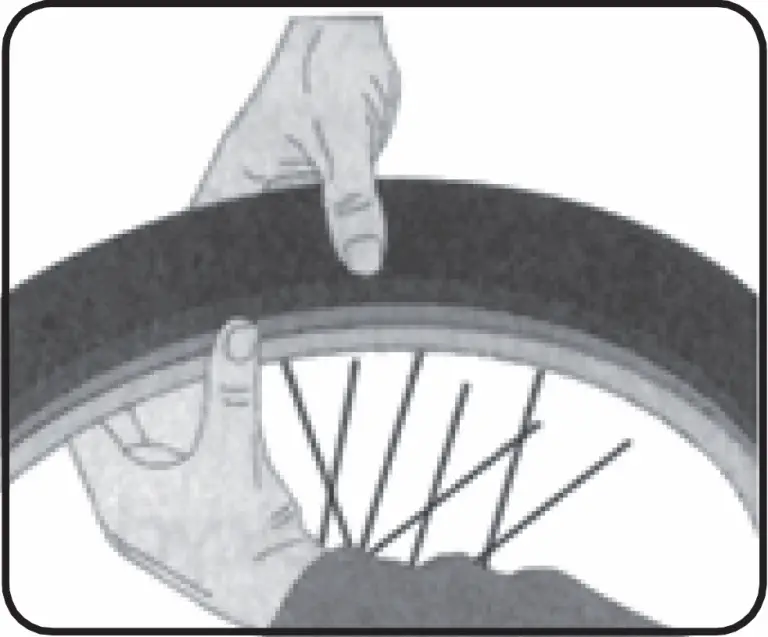
- Stand the wheel up on the firm surface with the valve stem on the bottom and grasp the upper part of the tyre with both hands. Try to roll the tyre off the far side of the rim.
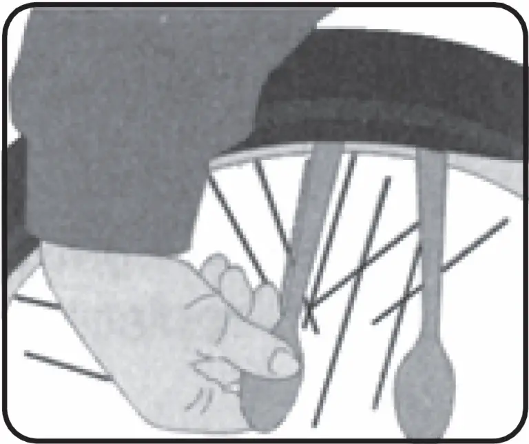
- With the wheel standing, use bicycle tyre tools for spoon handles with rounded ends (at least two-preferably three) to lift the bead on one side of the tyre off the rim. Be careful not to pinch the inner tube between the tyre tools and the tyre bead or rim. Once you have got the bead off for about one fourth of the circumference of the tyre using the tools, the rest can usually be pulled off by hand.
- With the bead on one side of the tyre completely off the rim, you can now pull the inner tube out from between the tyre and rim everywhere except in they are of the valve stem.
- It should now be easy to pull the tyre the rest of the way off the rim. Start at the side of the wheel opposite the valve stem and simply lift the bead of the tyre up over the side of the rim and pull it off.
Frequently check the tyre inflation pressure because all tyres lose air slowly over time. For extended storage, keep the weigh of the bicycle off the tyres.
Inspection of Bearings
- Maintenance: Frequently check the bearings of the bicycle. Have a bicycle service shop lubricate the bearings once a year or any time they do not pass the following tests.
- Head Tube Bearings: The fork should turn freely and smoothly at all times. With the front wheel off the ground, you should not be able to move the fork up, down, or side-to-side in the head tube.
- Crank bearings: The crank should turn freely and smoothly at all times and the front sprockets should not be loose on the crank. You should not be able to move the pedal end of the crank from side-to-side.
- Wheel bearing: Lift each end of the bicycle off the ground and slowly spin the raised wheel by hand. The bearings are correctly adjusted if:
The wheel spins freely and easily. The weight of the spoke reflector when you put it toward the front or rear of the bicycle causes the wheel to spin back and forth several times. There is no side-to-side movement at the wheel rim then you push it to the side with light force.
Lubrication / Maintenance
WARNING: Do not over lubricate. If oil gets on the wheel rims or the brake shoes, it will to reduce brake performance and a longer distance to stop the bicycle will be necessary. Injury to the rider or to others can occur.
The chain can throw excess oil onto the wheel rim. Wipe excess oil off the chain.
Keep all oil off the surfaces of the pedals where your feet rest.
Using soap and hot water wash all oil off the wheel rims, the brake shoes, the pedals, and the tyres. Rinse with clean water and dry completely before you ride the bicycle.
Lubrication and Adjustment – One Piece Cranks
To adjust the free play in a one piece type bottom bracket, loosen the locknut on the left side by turning in clockwise and tighten the adjusting cone counter-clockwise using a screwdriver in the slot. When correctly adjusted, re-tighten the locknut counter-clockwise. To disassemble:
- Remove the chain from the chainwheel.
- Remove the left pedal by turning the spindle clockwise.
- Remove the left side locknut by turning it clockwise and remove the keyed lock-washer.
- Remove the adjusting cone by turning it clockwise with a screwdriver.
- Remove the left ball retainer, slide the crank assembly out of the frame to the right, and remove the right ball retainer.
Clean and inspect all bearing surfaces and ball retainers, and replace any damaged parts. Pack the ball bearing retainers with grease, then re-assemble in the reverse of the above procedure.
12 Month Warranty
Kmart Australia Ltd warrants your new product to be free from defects in materials and workmanship for the period stated above, from the date of purchase, provided that the product is used in accordance with accompanying recommendations or instructions where provided. This warranty is in addition to your rights under the Australian Consumer Law.
Kmart will provide you with your choice of a refund, repair or exchange (where possible) for this product if it becomes defective within the warranty period. Kmart will bear the reasonable expense of claiming the warranty. This warranty will no longer apply where the defect is a result of alteration, accident, misuse, abuse or neglect.
Please retain your receipt as proof of purchase and contact our Customer Service Centre on 1800 124 125 (Australia) or 0800 945 995 (New Zealand) or alternatively, via Customer Help at Kmart.com.au for any difficulties with your product. Warranty claims and claims for expense incurred in returning this product can be addressed to our Customer Service Centre at 690 Springvale Rd, Mulgrave Vic 3170.
Our goods come with guarantees that cannot be excluded under the Australian Consumer Law. You are entitled to a replacement or refund for a major failure and compensation for any other reasonably foreseeable loss or damage. You are also entitled to have the goods repaired or replaced if the goods fail to be of acceptable quality and the failure does not amount to a major failure.
For New Zealand customers, this warranty is in addition to statutory rights observed under New Zealand legislation.