
Installation and Programming Manual
● Prepare door, per additional instructions (included) before installing unit.
● IMPORTANT: Read instructions completely before beginning installation.
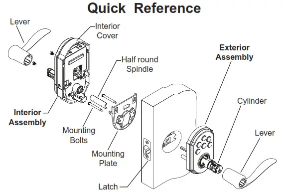
● Refer to “Quick Reference” area and illustrations to identify components.
√ Use the checklist below to assure completion of important steps.
□ ATTACH CONNECTOR …………………………………… Section 6
□ PROGRAM CODE(S) …………………………………………. Section 10 a, b, c
□ VERIFY OPERATION ……………………………………… Section 10 d
40490-01 SmartCode Lever Manual
a. Determine your backset, see figure 1.
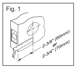
b. If the backset measured 2-3/4” (70mm), adjust the latch as follows: Using fingers, grasp the spring pin and move it down and over to the 2-3/4” (70mm) slot. (See figure 2).
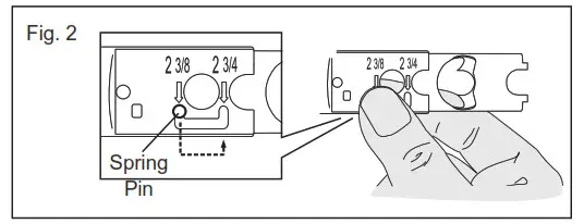
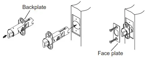
c. Prepare latch.
(1) Insert latch into the backplate,
(2) Insert latch and backplate into the door with the slant of bolt facing in the direction that the door closes.
(3) Place the desired faceplate cover backplate and fasten with two small screws.
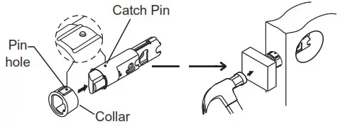
Align collar opening with the shape of the bolt and slide it on until the catch pins of latch snap into the pinholes of the collar. Install latch with the slant of bolt facing in the direction that the door closes. Use a woodblock to install the latch. Note, should collar require removal, squeeze collar hard at sides and remove.
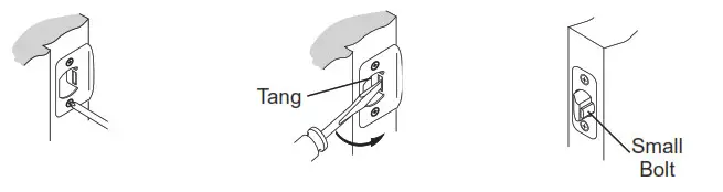
d. Install strike plate onto door jamb using two small screws. Minor loose door fit may be reduced by adjusting tang. Note, the lock will not lock properly if the smaller bolt of latch enters the strike hole. Reposition strike plate if required.
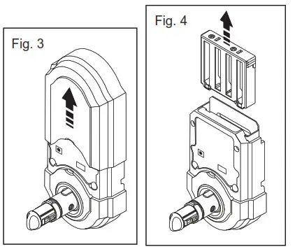
a. Remove the cover from the assembly by sliding the cover up and off, see figure. 3
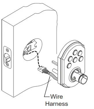
b. Remove the battery case from the interior assembly by lifting the case up and out and set aside, see figure 4.
Important before proceeding:
1. Verify that position #2 of the “Settings Switch” is in the OFF position. (Refer to section 11.)
2. Work with the door open (away from the jamb) to avoid accidental lockout.
Place the exterior assembly flush onto the door, threading the wire harness under the latch.
Route the connector of the wire harness through the slot at top of the mounting plate. Insert the long screws to engage exterior assembly. Tighten screws to secure – making sure that both the plate and the exterior assembly are flush against the door and vertically aligned with the edge of the door.
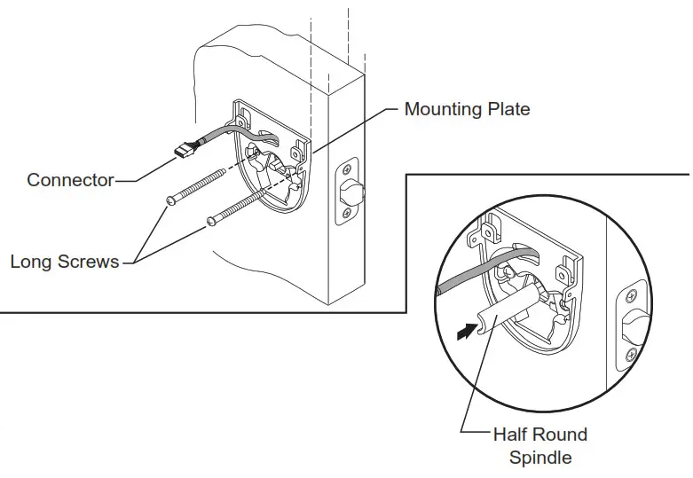
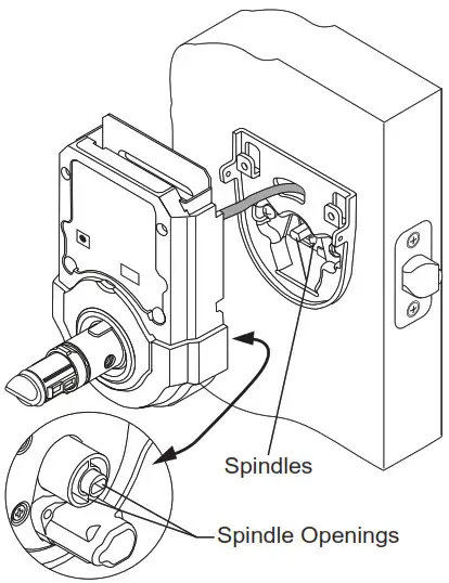
Insert the half-round spindle through the latch fully – to engage with the exterior assembly.
Important Note: To prevent damage, always handle the wire harness at the connector (do not pull wires).
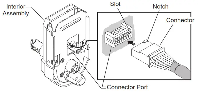
a. Align the connector with the connector port of the interior assembly, matching notch to slot.
b. Once aligned, push the connector in firmly to connect.
a. Tucking any excess wire back into the slot of the mounting plate, place the interior assembly on the door, aligning the spindles with the spindle slots of interior assembly.
b. Once flush on the door, insert and tighten small screws to secure assembly onto the mounting plate.
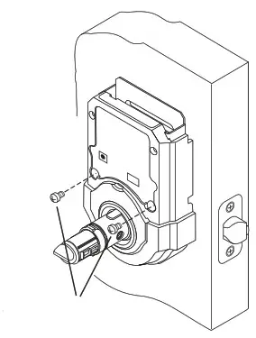
Small Screws
Note: To aid insertion of screws, approach the screw holes with the screw loaded onto the screwdriver.
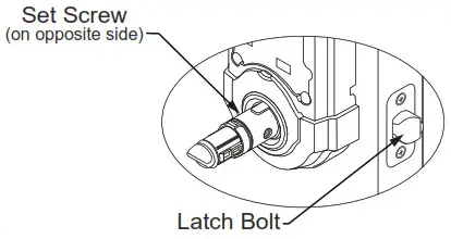
a Check both the interior and the exterior assemblies, to make sure the set screw is located on the opposite side, (the side furthest away from the latch bolt). If correctly positioned proceed to step c, if it is not on the proper side, remove and switch the set screw as directed in the following step – step b.
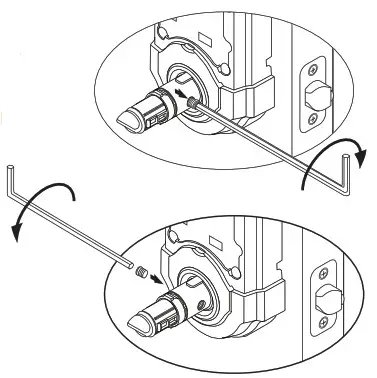
b. Using the tool provided, remove the set screw by unscrewing it in a clockwise direction (this is the reverse direction of what might feel normal). Reposition set screw to the other side and screw it in fully, using a counterclock direction (again this is the reverse of the normal direction).
c. Install interior lever and tighten set screw clockwise.
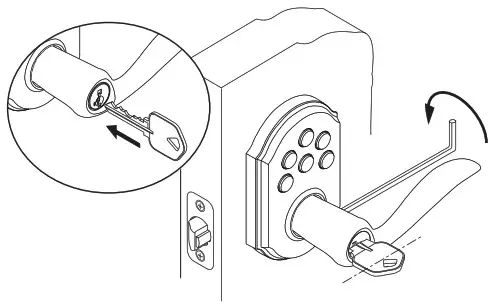
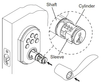
d. To install the exterior lever, first remove the key from the cylinder and insert the cylinder into the lever shaft, making sure the sleeve of cylinder is positioned near the keyway. Note that the cylinder will not seat back fully at this time. Slide the lever on smoothly, aligning ribs inside the lever with the lever shaft (lever will not seat all the way until completing step e).
e. Insert the key into the cylinder and rotate it clockwise to the horizontal position, then press the lever to seat into the assembly. With the key still in the horizontal position, tighten the set screw clockwise to secure the lever.

f. Test the locking and unlocking function.
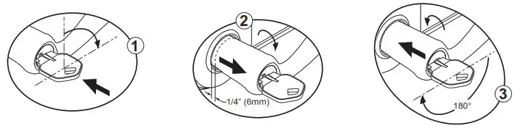
If you cannot lock the unit from the exterior or cannot rotate the interior turn piece, proceed with the following steps to remedy the situation. 1. Insert the key and rotate clockwise to the horizontal position. 2. Loosen the set screw and pull the lever away from the unit, about 1/4”. 3. Rotate the key 180° clockwise. With the key remaining in the horizontal position, push the lever back to the seat and tighten the set screw. 4. Test the locking and unlocking function and repeat these steps if required.
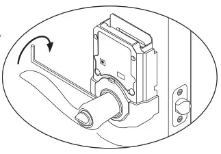
Action of exterior lever: When the unit is in the locked position the exterior lever is still allowed to turn, but it will not retract the latch. When the unit is in the unlocked position, the exterior lever will turn firmly, retracting the latch for entry.
Important note should you need to remove the exterior lever: 1. insert the key into the exterior lever and rotate clockwise to a horizontal (unlocked) position. 2. Loosen set screw and pull the lever, cylinder, and key – away from keypad assembly.
![]()
Install the new batteries as indicated in the illustration. Make sure batteries lie flat in the holder. For best performance, rechargeable batteries are not recommended.
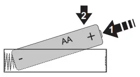
Do not dispose of in fire, recharge, put in backward, disassemble, mix with used or other battery types. May explode or leak and cause personal injury.
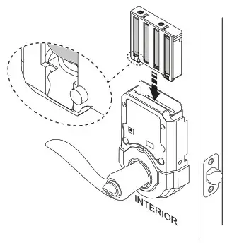
b. Install battery pack into a unit as shown. The unit will beep and the LED will flash green.
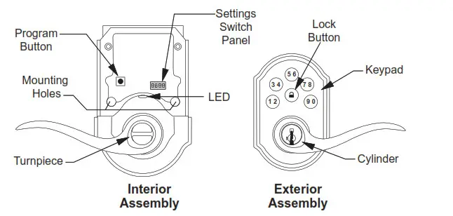
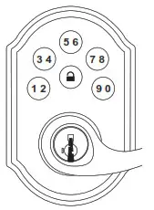
How the keypad works:
Each button represents two numbers (i.e. 1 and 2 for the first button). You only need to push the button once to get either 1 or 2. For example: If your code is 1-2-5-6-8,
■ Press the 12 button once to get number 1.
■ Press the 12 button once to get number 2.
■ Then press the 56 button once to get number 5.
■ Then press the 56 button once to get number 6.
■ Finally press the 78 button once to get number 8.
● A programmed code can be from four (4) to eight (8) digits long.
● For maximum security an 8 digit code is recommended.
● Up to 4 user codes can be entered.
● Excess delay in the programming steps once started will cause unit to beep twice and will require you to restart from step (10a).
Programming the 1st user code.
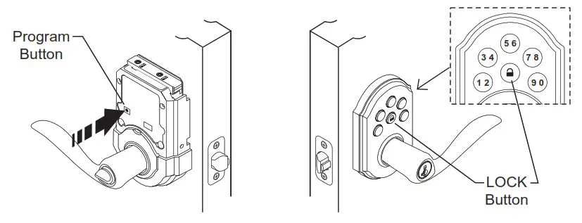
a. Press the program button on the interior unit once.
b. Enter in 4 to 8 digit code onto the keypad.
c. Press the “LOCK” button to save code.
d. Press the “LOCK” button and re-enter the code to test. The unit should go to the unlocked position allowing the exterior lever to retract the latch. If it does not go to the unlock position, repeat steps (a) through (c).
Note: Programming instructions can also be found on interior of lock.
Programming the 2nd user code.
a. Press the program button on the interior unit twice.
b. Enter in 4 to 8 digit code onto the keypad.
c. Press the “LOCK” button to save code.
d.Press the “LOCK” button and re-enter the code to test. The unit should go to the unlocked position allowing the exterior lever to retract the latch. If it does not go to the unlock position, repeat steps (a) through (c).
10. Continued…..
Programming the 3rd user code.
a. Press the program button on the interior unit three times.
b. Enter in 4 to 8 digit code onto the keypad.
c. Press the “LOCK” button to save code.
d. Press the “LOCK” button and re-enter the code to test. The unit should go to the unlocked position allowing the exterior lever to retract the latch. If it does not go to the unlock position, repeat steps (a) through (c).
Programming the 4th user code.
a. Press the program button on the interior unit four times.
b. Enter in 4 to 8 digit code onto the keypad.
c. Press the “LOCK” button to save code.
d. Press the “LOCK” button and re-enter the code to test. The unit should go to the unlocked position allowing the exterior lever to retract the latch. If it does not go to the unlock position, repeat steps (a) through (c).
CAUTION: Prevent unauthorized entry. This lock can be opened using four different codes that are randomly set at the factory. Upon installation and set-up, replace all of these codes with your own. Since anyone with access to the power board can change these codes, you must restrict access to the power board and routinely check both codes to assure they have not been altered without your knowledge.
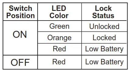
Switch #1  Status LED blinks every 5 seconds when in the ON position. Note: The low battery RED LED cannot be disabled.
Switch #2  Enables the AUTO LOCK when in the ON position. With Auto-Lock enabled, SmartCode will automatically relock the door 30 seconds after unlocking.
Switch #3  Enables the AUDIO sound (Beeper) when in the ON position. The keypad will now light red/green when buttons are pressed.
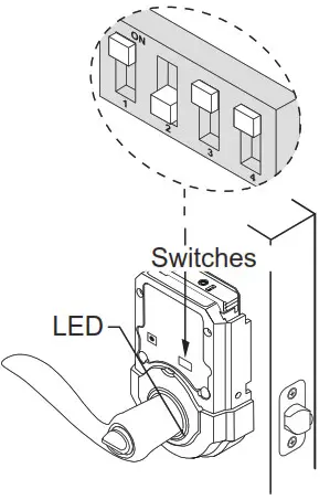
Switch #4  Extra switch with NO FUNCTION.
Hint: for easier access, use a ballpoint pen to operate the switches.
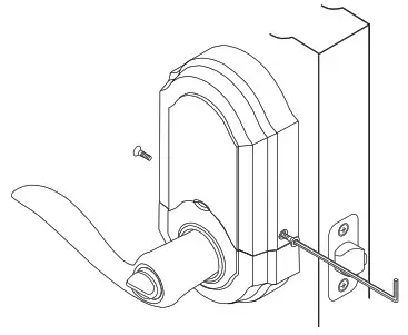
a. Once you have completed setup and programming, you can install the cover. Position cover over the unit and press it onto the top portion of the unit. Once it is flush against the door, slide it down into place.

b. Optional : To avoid tampering you may choose to secure the cover by installing a small screw to both sides of the cover – using the hex wrench supplied.
- The interior LED
● Regardless of switch #1 position, under “Low Battery” condition – red LED will flash every 5 seconds. - The exterior Keypad (when switch #3 is OFF).
● After a correct code is entered, the keypad will flash red multiple times for approximately 3 seconds. - The Audio Indicator (when switch #3 is in the ON position).
● After a correct code is entered the unit beeps multiple times for approximately 3 seconds.
Note: For future battery replacement, remove the battery pack, replace batteries (see section 9), and simply reinsert the battery pack as shown, a beep and a Green LED flash will indicate success.
a. Keypad Back Light
● When the door is in the locked position, press the lock button to light up the keypad. In a “very low battery” condition the keypad will not light up.
b. Keypad light signals
● Switch 3 off – the keypad will flash red every time you press a button.
● Low Battery Warning – After a correct code is entered, the keypad will flash red multiple times for approximately 3 seconds.
● Incorrect Codes Entered – when three incorrect codes are entered into the SmartCode the keypad will flash red and the beeper will sound for 15 seconds. The keypad will not allow input for 60 seconds after which you can re-enter a code and try again.
Q: How long will the Smart Code operate on a set of batteries?
A: Based on 15 operations per day, a single set of Alkaline batteries will operate the SmartCode for over 2 years.
Q: What type of batteries do you recommend?
A: For best results, use new non-rechargeable Alkaline batteries only.
Q: I just installed a Smart Code on my door but it does not operate correctly
A: Make sure you have installed the cylinder properly, review step 8.
Q: I removed the battery pack momentarily and my lock does not work anymore.
A: The system did not initialize properly due to the remaining charge. To correctly perform the following:
a. Remove the battery pack
b. Press “Program” button three times
c. Wait 10 seconds.
d. Insert battery pack.
e. The system should flash the Green LED and beep, indicating proper initialization
f. Repeat a-d if initialization failed
Q: I am planning to be away for several months; will my lock operate when I get back?
A: When the system is idling, it consumes minimum power (very close to battery shelf life.) With alkaline batteries, the lock should be operable after years of idle. See also Questions and Answers below.
Q: What settings should I use to get the maximum battery life out of my lock?
A: Set “Status LED” (SW1) and “Auto-lock” (SW2) to the off position.
WARNING: This Manufacturer advises that no lock can provide complete security by itself. This lock may be defeated by forcible or technical means or evaded by entry elsewhere on the property. No lock can substitute for caution, awareness of your environment, and common sense. Builder’s hardware is available in multiple performance grades to suit the application. In order to enhance security and reduce risk, you should consult a qualified locksmith or other security professional.
For , call
1-800-327-5625 for USA & CANADA
or visit, www.kwikset.com
For Weiser product, call
1-800-677-5625 USA, 1-800-501-9471 CANADA
or visit, www.weiserlock.com


