![]()
OWNER’S & INSTALLATION MANUAL
AIR CONDITIONER
Please read this installation manual completely before installing the product. Installation work must be performed in accordance with the national wiring standards by authorized personnel only. Please retain this installation manual for future reference after reading it thoroughly.
Simple Wired Remote Controller
 www.lg.com
www.lghvac.com
Copyright © 2018 – 2020 LG Electronics Inc. All Rights Reserved.
TIPS FOR SAVING ENERGY
Here are some tips that will help you minimize power consumption when you use the air conditioner. You can use your air conditioner more efficiently by referring to the instructions below:
- Do not cool excessively indoors. This may be harmful to your health and may consume more electricity.
- Block sunlight with blinds or curtains while you are operating the air conditioner.
- Keep doors or windows closed tightly while you are operating the air conditioner.
- Adjust the direction of the airflow vertically or horizontally to circulate indoor air.
- Speed up the fan to cool or warm indoor air quickly.
- Open windows regularly for ventilation as the indoor air quality may deteriorate if the air conditioner is used for many hours.
- Clean the air filter once every 2 weeks. Dust and impurities collected in the air filter may block the airflow or weaken the cooling / dehumidifying functions.
For your records
Staple your receipt to this page in case you need it to prove the date of purchase or for warranty purposes. Write the model number and the serial number here: ________________________________________
Model number : ______________________________________
Serial number : _______________________________________
You can find them on a label on the side of each unit.
Dealer’s name : _______________________________________
Date of purchase : _____________________________________
IMPORTANT SAFETY INSTRUCTIONS
READ ALL INSTRUCTIONS BEF ORE USING THE APPLIANCE.
Always comply with the following precautions to avoid dangerous situations and ensure peak performance of your product
 WARNING
This symbol indicates a potentially hazardous situation that, if not avoided could result in death or serious injury.

This symbol indicates a potentially hazardous situation that, if not avoided, may result in minor or moderate injury.
WARNING
Installation
- For electrical work, contact the dealer, seller, a qualified electrician, or an authorized service center.
- Do not disassemble or repair the product. There is a risk of fire, electric shock, explosion, equipment malfunction, or injury.
- Request to the service center or installation specialty store when reinstalling the installed product.
- There is a risk of fire, electric shock, explosion, equipment malfunction, or injury.
- Do not disassemble, fix, and modify products randomly.
- There is a risk of fire, electric shock, explosion, equipment malfunction, or injury.
- The product shall be installed according to the national standards and local code.
- Apply totally enclosed noncombustible conduit in case of local building code requiring plenum.
- Use appropriate unit mounting procedures.
- Avoid direct sunlight.
- Avoid moist areas.
In-Use
- Do not place flammable objects close to the product.
- There is a risk of fire, electric shock, explosion, equipment malfunction, or injury.
- Do not allow the product to get wet.
- There is a risk of fire, electric shock, explosion, equipment malfunction, or injury.
- Avoid dropping the product.
- There is the risk of fire, electric shock, explosion, equipment malfunction, or injury.
- If the product gets wet, contact your dealer or authorized service center.
- There is a risk of fire, electric shock, explosion, equipment malfunction, or injury. If the instructions are not followed, it may cause death or severe injury to the user.
- Do not use sharp or pointed objects on the product.
- There is the risk of fire, electric shock, explosion, equipment malfunction, or injury.
- Do not touch or pull the lead wire with wet hands.
- There is a risk of product breakdown or electric shock.
Installation
- The Limited Warranty is void and of no effect, and LG will have no liability hereunder to any Customer or the third party, to the extent any of the following occur: acts, omissions, and conduct of any and all third parties including, but not limited to, the installing contractor and any repairs, service or maintenance by unauthorized or unqualified persons.
- Do not install the unit in potentially explosive atmospheres.
In-use
- Do not clean using powerful detergents like solvent but use soft cloths.
- There is a risk of fire, electric shock, explosion, equipment malfunction, or deformation.
- Do not press the screen using powerful pressure.
- There is a risk of product break-down or malfunction.
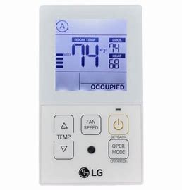
DESCRIPTION
Simple wired remote controller
Accessories
 |
 |
| Remote controller fixing screws (2EA) | OWNER’S &INSTALLATION MANUAL |
Icon Description![]()
| Function | Icon | Description |
| Operation mode | Auto mode • Product automatically switches between cooling and heating modes. |
|
| Cooling mode • Product is running in cooling mode. |
||
| Dehumidification mode • Product is running in dehumidifying mode. |
||
| Heating mode • Product is running in heating mode. |
||
| Fan only operating mode • Product is running only the fan for ventilation. |
||
| Subfunction | Auxiliary heat control • Product operates Auxiliary Heat Control in heating mode. |
| Function | Icon | Description |
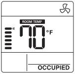
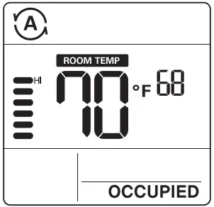
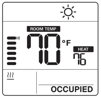
| Temperature | Current temperature • Display current room temperature. |
|
| Cooling setpoint temperature • Temperature set point for cooling operation. |
||
| Heating setpoint temperature • Temperature setpoint for heating operation. |
||
| Fan speed | Displays current fan speed POW: Fan speed – Power AUTO: Fan speed – Auto HI: Fan speed – High MED: Fan speed – Medium LO: Fan speed – Low SLO: Fan speed – Weak |
|
| Controller mode | Set back operation mode • Controller operates a set-back operation. |
|
| Override mode • Occupied/Unoccupied state change. |
||
| Product state monitoring | Command received from the central controller or outdoor unit. | |
| Slave indoor unit on a heat pump system prevents changing to a mode not compatible with the current outdoor unit mode. |
||
| Outdoor unit running. | ||
| Indoor unit pre-heating operation running. | ||
| Defrost operation running. | ||
| Function setting | TIME SET | Override timer setting step. |
| TEMP.SET | Setback cooling/heating temperature setting step. | |
| It is displayed when is set. |
OPERATION INSTRUCTIONS – Standard Operation
Press ![]() the button several times until the desired mode is selected.
the button several times until the desired mode is selected.
Whenever pressing the button, the selected operation mode is changed as Auto -> cooling -> Dehumidification -> Heating -> Fan -> Auto··· .
Cooling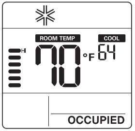 Heating
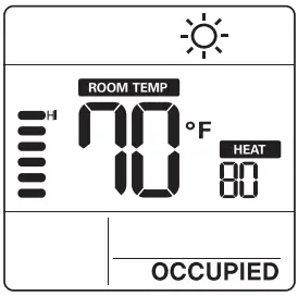
- Adjust the desired temperature by pressing buttons.
![]() Note
Note
- The setting temperature range is as below.
- Cooling: 64°F ~ 86°F(18°C ~ 30°C) 60°F ~ 86°F(16°C ~ 30°C) (For some models)
- Heating: 60°F ~ 86°F(16°C ~ 30°C)
 If connecting to an indoor unit with a dual setpoint function.
Cooling : 50 ~ 99 °F (10 ~ 37.5 °C)
Heating: 40 ~ 90 °F (4 ~ 32 °C)- The heating mode is not available for cooling exclusive models.
Cooling mode
The set temperature is lower than room temperature.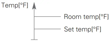
Heating mode
The set temperature is higher than room temperature.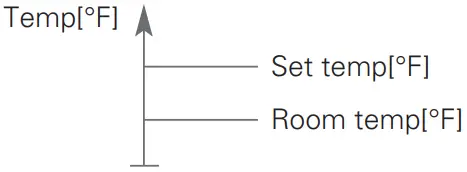
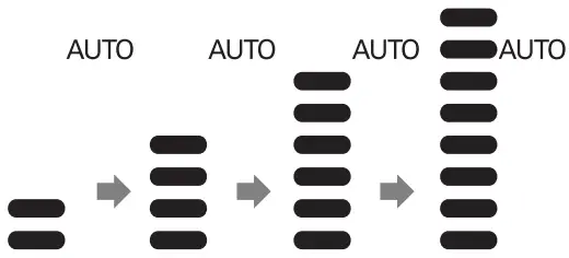
Fan speed
You can simply adjust the desired fan speed.
- Press
 the button to change the fan speed.
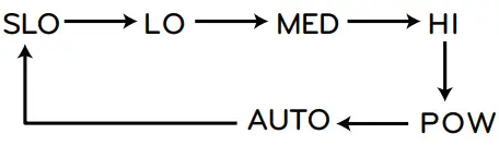
- It is displayed as an animation effect like below.
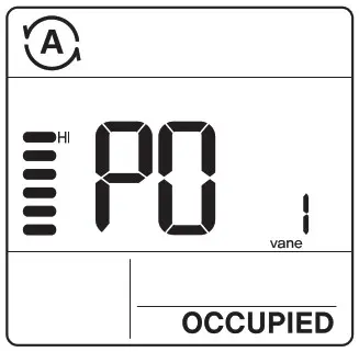
Power cooling
- Press the button until ’Po’ is displayed.
![]() NOTE!
NOTE!
- Power cooling quickly lowers the indoor temperature.
- Desired temperature: 64°F(18°C)
- Fan speed: Power fan speed
- Fan direction: Current fan direction
- If fan speed or desired temperature is changed, the power cooling is cleared, and it operates in the cooling operation mode.
- This function may not be supported, depending on the models.
Dehumidification
Fan
 Press the button repeatedly to adjust the fan speed.
![]() NOTE
NOTE
- In dehumidification/fan mode
- You cannot adjust set temperatures.
- The menu items of fan speed might not be partially selected depending on the product functions.
- Using dehumidification mode in the rainy season or high humidity climates, you can feel dehumidification and cooling mode at the same time.
- Fan mode only circulates the indoor air without changing the room temperature.
Auto operation (Dual set points)
This function automatically manages the room temperature based on two types of set temperature(cooling and heating) and provides a comfortable environment.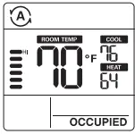
- Press the
 button to select auto mode(Dual setpoints control).
 - Press
 buttons and then the cooling and heating temperature will blink.
 - You can control the blinking temperature by pressing buttons.
![]() If you want to control each temperature, press the
If you want to control each temperature, press the ![]() button when the temperature icons blink.
button when the temperature icons blink.
Cooling operation state
Heating operation state
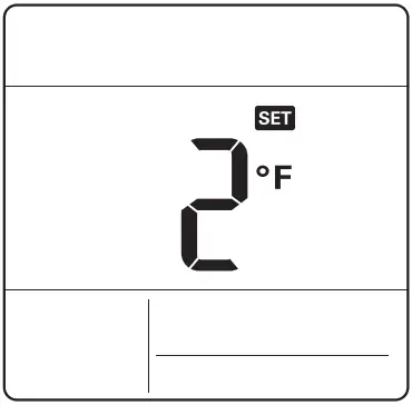
For the case of the cooling-only model, you can adjust the temperature from hot to cold, from “-2” to “2” based on “0”.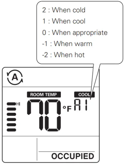
![]() NOTE
NOTE
- When remote controller has a connection with indoor unit that does not support ‘dual setpoint’, thermal operation function of indoor unit is replaced with ON/Off control from the wired remote, when the user sets target temperatures in the below ranges.
- cooling target temp. range : 87~99 °F (30.5~37.5 °C)
- heating target temp. range : 40~59 °F (4~15.5 °C).
Auto operation (Single set point)
This function automatically manages room temperature based on set temperature and provides a comfortable environment.
- Press button to select auto mode.
- Press buttons and then temperature will blink.
- You can control the blinking temperature by pressing bottons.
OPERATION INSTRUCTIONS – Sub Function
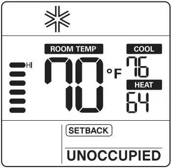
Setback
The setback operation returns to the set temperature until the setback operation is canceled.
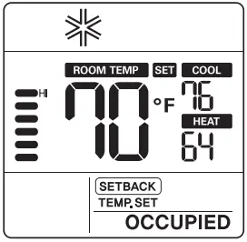
- Press
 button for 3 seconds, you can operate/cancel setback.
You cannot change the setting in setback operation, except to cancel the mode.
• ‘HL’ lock is displayed on the window.
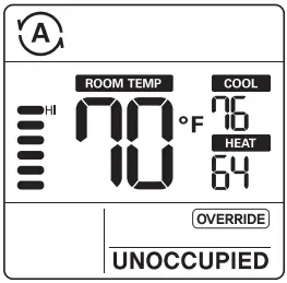
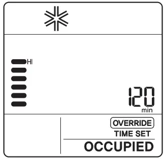
Override
The override operation temporarily returns to the set temperature until the override operation is canceled.
- Press button for 3 seconds, you can operate/cancel override.
You cannot change the setting in override operation, except to set sub function and cancel the mode.
• ‘HL’ lock is displayed on the window.
• It is only applied for ‘UNOCCUPIED’.
Press the ![]() button for 3 seconds. You can enter to sub function setting mode and press the
button for 3 seconds. You can enter to sub function setting mode and press the ![]() button repeatedly to change the sub function mode in the following order.
button repeatedly to change the sub function mode in the following order.
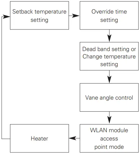
Change temperature – When it connect with single set point control product.
Setting the setback temperature
- Press button for 3 seconds.
- Press button to move the setback mode.
- Press button to select cool/heat temperature.
- Press button to change the temperature.
- Press button to set temperature.
- Press button for 3 seconds.
Setting the override time
- Press button for 3 seconds.
- Press button to move the override mode.
- Press button to select override time.
- Press button to set override time.
- Press button for 3 seconds.
You can set in units of 30 minutes.
Dead band (Dual set points)
This function sets the minimum difference between heating and cooling set points.
![]() This function is used in connection with the dual set points control product.
This function is used in connection with the dual set points control product.
- Press button for 3 seconds.
- Press button to move the dead band mode.
- Press button to change the dead band temperature. (0 ~ 10°F/0 ~ 5°C)
- Press button to set temperature.
- Press button for 3 seconds.
Change temperature setting (Single set point)
Change temperature is the function to setup air-cooling and heating drive automatically changeable according to the temperature at single set point auto operation mode.
![]() This function is used in connection with the single set point control product.
This function is used in connection with the single set point control product.
- Press button for 3 seconds.
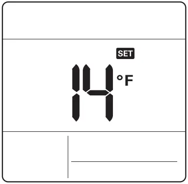
- Press button to move the change temperature setting mode.
- Press button to change the temperature. (2 ~ 14°F/1 ~ 7°C)
- Press button to set temperature.
- Press button for 3 seconds.
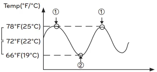
Example of using change temperature Condition
- Mode: Auto mode
- Temperature: 72°F(22°C)
- Change Temperature: 6°F(3°C)
In case of the above conditions, it operates as in the graph.
① : Cooling operation start
② : Heating operation start
![]() This function may not work in some products.
This function may not work in some products.
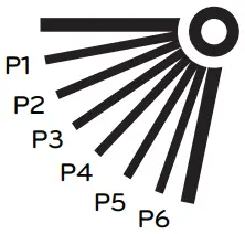
Vane angle control
This function is to adjust airflow angle.
- Press button for 3 seconds.
- Press button to move the vane angle control mode.
- Press button to select indoor unit vane. (1,2,3,4,All)
- Press button to change the vane angle. (P1 ~ P6)
- Press button to set vane angle.
- Press button for 3 seconds.
Child lock
It is the function to prevent children or others from careless using.
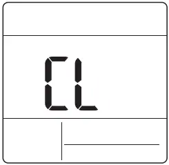
- Press button and botton for 3 seconds, you can operate child lock.
- As for the releasing method, press button and botton for 3 seconds.
At the time of initial setting of the ‘Child Lock’, the ‘CL’ will be indicated approx. 3 seconds at the temperature display section before resuming to the previous mode.
After the setting of the ‘CL’, if another button is setup, the button can not be recognized as the ‘CL’ is indicated at the temperature display section for approx. 3 seconds.
WLAN module access point mode
It is the function to operate WLAN (Wireless LAN) module connected to the product in access point mode.
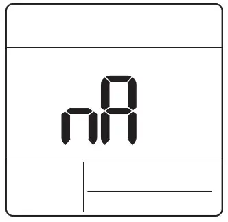
- Press button for 3 seconds.
- Press button to move the WLAN module access point mode.
- While WLAN module is operating in access point mode, the term of ‘AP’ blinks on the screen of wired remote controller.
- Press button for 3 seconds.
This function is only available for select models that support the WLAN Module.
Refer to the installation manual of indoor unit whether available or not.
Heater
It is the function to reinforce the heating capability by turning on the electric heater during the heating operation.
- Press button for 3 seconds.
- Press button to move the heater mode.
- Press button to select heater mode ‘on/off’
- Press button for 3 seconds.
This function may not work in some products.
Mode lock button
This function prevents changes to mode setting.
- Press
 button and button simultaneously for 3 seconds to use mode lock.
If you press the button while mode lock is in use, the following screen appears.
As for the releasing method, press button and botton for 3 seconds.
INSTALLATION INSTRUCTIONS
Installation
- Please fasten the back plate securely to the wall using the provided screws.
Please ensure to not bend the back plate as this could cause issues with installation.
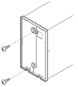
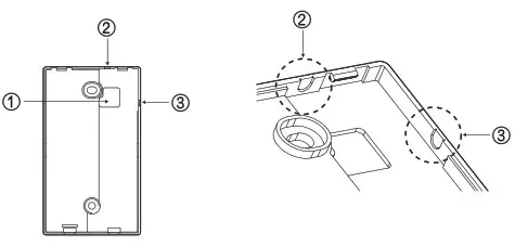
- There are three different wiring configurations.
① Through the surface of the wall
② Upper section of Remote Controller
③ Right section of Remote Controller
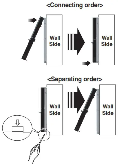
- Please secure remote controller upper part into the backplate attached to the surface of the wall, as pictured below, and then, connect with backplate by pressing lower part.
Please make sure to leave no gaps on the top, bottom, left or right sides between the remote controller and backplate. Before assembly with the backplate, arrange the Cable not to interfere with circuit parts.
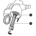
Remove remote controller by inserting a screwdriver into the lower separating holes and twisting to release the controller from backplate.
There are two separating holes. Please individually separate one at a time. Please be careful not to damage the inside components when separating.
- Please refer to the following directions when connecting the indoor unit and the wired remote controller together.
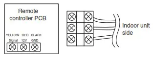
![]() CAUTION
CAUTION
When installing the wired remote controller do not bury it in the wall. (It can cause damage in the temperature sensor.)
Do not exceed 164ft(50m) for cable length.
(It can cause communication error.)
Specification of LG supplied extension cable : AWG 24, 3 conductor or above. (Model : PZCWRC1)
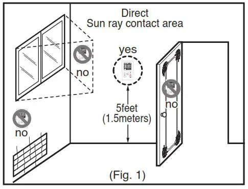
Remote controller installation
Since the room temperature sensor is in the remote controller, the remote controller box should be installed in a place away from direct sunlight, high humidity and direct supply of cold air to maintain proper space temperature. Install the remote controller about 5ft(1.5m) above the floor in an area with good air circulation at an average temperature.
Do not install the remote controller where it can be affected by:
-
- Drafts, or dead spots behind doors and in corners.
- Hot or cold air from ducts.
- Radiant heat from sun or appliances.
- Concealed pipes and chimneys.
- Uncontrolled areas such as an outside wall behind the remote controller.
- This remote controller is equipped with LCD display. For proper display of the remote controller LCD’s, the remote controller should be installed properly as shown in
Fig.1. (The standard height is 4~5 ft (1.2~1.5 m) from floor level.)
 When installing more than 2 units of air conditioner to one Thermostat, please connect as pictured to the right.
 - Set one indoor unit to master and the remaining to slave.
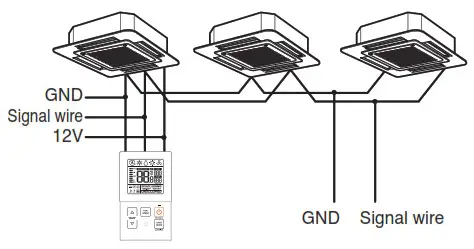 When controlling multiple indoor units with one Thermostat, you must change the master/slave setting from the indoor unit.
 - Once DIP S/W is set, recycle power. When recycling power, please remain in OFF position for at least 1 minute for new settings to take effect.
- For ceiling type cassette and duct product group, change the switch setting of the indoor PCB.
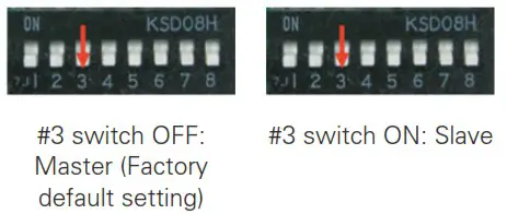
- For wall-mount type and stand type product, change the master/slave setting with the wireless.
Thermostat. (Refer to wireless Thermostat manual for additional information)
When controlling the group, some advanced functions (excluding basic operation setting, fan level Low, med, high, Thermostat lock setting and time setting) may be limited.
INSTALLER SETTING
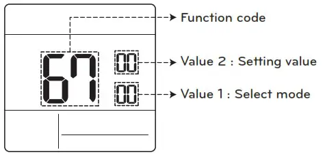
How to enter installer setting mode
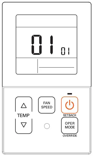
- Press
 button and button simultaneously for 3 seconds to enter the installer setting mode.
 - When you enter the setting mode initially, function code is displayed on the LCD screen.
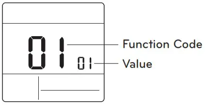
- Press button to select function code.
- Press button to change value.
- Press button to set value.
- Press button and button simultaneously for 3 seconds to exit installer setting mode.
![]() CAUTION
CAUTION
Installer setting mode is to set the detail function of the remote controller. If the installer setting mode is not set correctly, it can cause problems to the product, user injury or property damage. This must be set by an certificated installer, and any installation or change that is carried out by a non-certificated person should be responsible for the results. In this case, free service cannot be provided.
<Installer setting code table>
1) General air-conditioner product
| Code No. | Function Name | Value | Description |
| 1 | Test run mode | 00: Normal operation (Default) 01: Initiate cooling test mode 02: Initiate heating test mode |
Initiate IOU test mode |
| 2 | Address setting | 02 : xx: central control address number (00-FR |
Assign a unique hexadecimal address when used with central controller. |
| 3 | E.S.P. function | [Select fan speed) 01 : Slow 02 : Low 03 : Middle 04 : High 05 : Power E.SP value : 0130-255 |
Please refer to engineering manual for specific product data. “000” is the number displayed for factory settings. If code3 valuels) are changed from default setting 1000) then code5. code6 & code32 values will not be used. Only selected products have five speeds. |
| 4 | Temperature sensor setting | 01 : Use wired remote controller sensor (Default) 02 : Use indoor unit return sensor 03 : 2TH sensor – Cooling : higher sensor value is used – Heating : lower sensor value is used |
Select the thermistor value that will be used to control room temp. |
| 5 | Ceiling height | [Ceiling height) 01 : Low, 02 : Standard (Default) 03 : High 04 : Very high |
Simplified air volume setting for cassette and console product. Select the value that cooresponds to the ceiling height the product is installed at |
| 6 | Static pressure | Zone state – E.S.P standard value 01 : Variable -High 02 : Fixed-High 03 : Variable-Low 04 : Fixed-Low |
Simplified air volume setting for ducted product Select the value that corresponds to the type of duct system attached to the product. |
| 8 | Override master/slave setting |
00 : Slave unit [Default)01 : Master unit | This function is available for use with MV HP system. One IOU is selected as a master and will communicate its mode to the other slave IDUs. The slave IOUs will probbt/gray out opposite mode selection. |
| 9 | Dry contact mode setting |
00 (Default): – Input closed = Enable remote – Input open = Stop IOU and disable remote 01 : – Input closed = Start IOU and enable remote – Input open = Stop IOU and disable remote |
This function is available for use with simple dry contact. |
| 12 | Celsius /Fahrenheit switching |
00 : Celsius 01 : Fahrenheit (Default) |
Celsius or Fahrenheit. |
| 15 | Heating thermal on off setting | 0: Default. Each indoor unit has different value with product type. 1 : +8 °F/+12 °F 1+4 °C/+6 °C) 2 : +4 °F/+8 °F (+2 °C/+4 °C) 3: -2 °F/ +2 °F ft °C/+1 °C) 4 : -1 °F/ +1 °F (-0.5 °C /+0.5 T) ‘Option 4 is available under fahrenheit unit use condition of codel2. |
It can adjust the heating thermal on/off temperature according to the field environment in preparation for over heating or heating claim. |
| 17 | Celsius temperature unit | 00: Celsius IT control (Default) 01 : Celsius 0.5°C control | Temperature resolution |
| 18 | Emergency heater setting | [Value 1] 00 : Disable emergency heater (Default) 01 : Enable emergency heater [Value 2] 0: Disable emergency heater in low ambient temperature 1-15 : Enable emergency heater at low ambient temperature 01 : -10F, 02: -5F. 03 : OF. 04 : 5F. 05 : 1OF 06 : 15F, 07: 20F. 08 : 25F. 09: 30F. 10: 35F 11 : 40F, 12 : 45F. 13 : 50F. 14 : 55F. 15: 60F [Value 3] 0: Fan off 1 : Fan on (Fan is off when heater is off I |
Setting value 1 enables auxiliary heater to be used when ODU has an error code. Setting value 2 enables ODU to be locked out based on selected outside temperature and enables auxiliary heater to be used Setting value 3 determines fan operation during thermal on with auxiliary heater |
| 19 | Function setting in group control | 00 : Disable extended functions (Default) 01 : Enable extended functions |
Standard function : On/Off. Mode. Air flow (Low/Mid/Highl. Set point. Schedule Extended function: Air angle controffallk Swirl. Air up/down. Air righOeft. Energy saving cooling. Fan Auto |
| 20 | Plasma purification | 03 : Disable 01 : Enable (Default) |
It is a function to set whether Plasma purification is enable or not. |
| 21 | Auxiliary heat control | 00 : Manual heat control disabled 01 : Manual heat control enabled (Default) | This setting allows user to enable/disable the auxiliary heat in sub function menu. |
| 25 | External auxiliary heat kit | 00 : Not installed 01 : Installed (Default) |
This function must be enabled to use external auxiliary heat kit. |
| 26 | Check indoor unit address number | XX(assigned address) | Display ODU assigned IDU address. |
| 27 | Cooling thermal onoff setting | 0: default. +1 °F/-1 °F1+0.5 °C/-0.5 °C) 1 : +12 °F/+8 °F 1+6 °C/+4 °C) 2 : +8 °F/+4 °F (+4 °C/+2 °C) 3: +2 °F/-2 °F (+1 °C/-1 °C) |
It can adjust the cooling thermal on / off temperature according to the field environment in preparation for over cooling or cooling claim. ‘This function available from Gen 4 indoor unit series. |
| 29 | Setting for refrigerant leak detector |
00 : Not installed (Default) 01 : Installed |
Enable this function after installing external refrigerant leakage detection device. |
| 30 | SW version | Display remote SW version | Remote SW version |
| 31 | Setting temperature range | 00 : 60-86°F(16-30°C) (Default) 01 : 40-994F(4-37.5°C) |
If the extended temperature range is set refer to the following. – Cooling 87-99’F (30.5-37.5°C) -> 86°F130t). – Heating 40-59’F (4-15.5°C)-> 60°F116°C). – If set on dual set points. it is changed to the current operation modelcooling or heating) of the indoor unit. |
| 32 | Static pressure step | 00 : Use static pressure (code 06) set value (Default) 01-11: Static pressure step (code 321 set value |
If code3 values) are changed from their default settings (000) then code32 values will not be used. Extended simplified air volume setting for ducted product |
| 33 | Guard timer | 00 0 minute 01 15 minutes (Default) 02:30 minutes 03:45 minutes 04 :60 minutes |
Minimum time that must elapse before system can change to opposite mode. (example: change from heat to cool mode) |
| 34 | Set point range lock | 00 : Disable (Default) 01 : Enable | limits the heating and coding setpolnt range that the user can select. For more detail information see the following instruction |
| 35 | Cooling thermal off fan operation | 00 : Fan low (Default) 01 : Fan off 02 : Previous fan setting |
Set the fan speed operation during cooling thermal off |
| 36 | Primary heater control | 00 HP first stage heat (Default) 01 HP last stage heat |
Installer to select heat pump to operate as first or last stage of heat with use of external heat kit |
| 37 | Hold enable/Disable | 00 : Hold disable (Default) 01 – Hold enable | Prevent or allow user to select hold function. |
| 38 | Air conditioner fan operation interlocked with ventilation |
00 : Fan low(Default) 01 • Fan off | If cassette has a ventilation kit installed then it is desirable to limit air from flowing through the air filter in a direction opposite of design flow. |
| 39 | IDU auto start setting | 00 : Enable auto restart (Default) 01 : Disable auto restart | Installer to select if IDU should be on or off after power is restored to IDU. |
| 40 | Occupancy duration time setting |
00:0 minute (Default) 01 10 minutes 02 30 minutes 03 :60 minutes |
Time that IDU is on after transition to occupied mode. |
| 41 | Simple dry contact setting ICN_CC connection) |
00: Simple dry contact auto identification (Default) : 01 : Disable the function. 02 : Enable simple dry contact function 03 : Enable simple dry contact function with CN_EXT port |
This function is used when simple dry contact unit is additionally installed in the indoor unit or the installed simple dry contact unit is removed. |
| 46 | Setting the fan continuous | 00 : Not used 01 : Used | It is the function to set the continuous operation of the indoor fan. Even if the room air temperature reaches the set point through the indoor unit operation it is the ability to keep set fan speed longer than does not setting. |
| 47 | Outdoor unit function setting master/slave | 03 : Outdoor unit function slave 01 : Outdoor unit function master |
This function make connected indoor unit as a master indoor unit that can set functions related to outdoor unit operation. Outdoor unit accepts for only one indoor unit that can set functions related to outdoor unit operation. |
| 48 | Function of indoor unit silent mode | 03 Not used 01 Silent mode low 02 Silent mode high |
It is the function to reduce the refrigerant noise occurred at the initial stage of the operation of the indoor unit at the heating mode. |
| 49 | Setting the outdoor unit defrost mode |
00: Not used 01 : Forced remove piled snow mode 02: Fast defrost mode 03 : Forced remove piled snow and fast defrost mode |
It is the function to select the defrost or snow remove function of the outdoor unit. |
| 51 | Setting temperature based fan speed ‘auto’ | . 03 Not used 01 : Use temperature-based fan speed ‘auto’ | Temperature-based fan speed ‘auto’ function is the function to change the fan speed according to the difference between the room temperature and the set point. |
| 52 | CN_EXT | 00 : Use installer code No. 41 setting value (simple dry contact setting value) 01 : Simple operation on/off 02 : Simple dry contact (It takes HL when operation is off.) 03 : Indoor unit single emergency stop 04 : Occupied / unoccuped 05 : Indoor unit all emergency stop * It can be set only when there is indoor unit emergency stop function. 06 : Wndow contact * It can be set only when there is window contact function. 07 : Wndow contact lock *It can be set only when there is window contact lock function. |
It is the function to set a purpose of digital input port(CN_EXTI of indoor unit PC8. |
| 56 | Outdoor unit cycle priority | <Select mode> < Step > 00 ‘ Not use INot use. Standby) 01 : Stand None by 02 : Cool ICooll 0-5 Step |
It is the function to clear the limit and set the operation mode when it is cleared. to be able to select the operation mode opposite to the operation mode of the outdoor unit currently in operation while the connected product is in slave mode. |
| 57 | Outdoor temperature for heating stages |
<Select mode> <Setting range> 01 : Use/Not use lUse/Not usel 02 : T1 None 03 : PT ITt setting range) -10-60°R-23-16°C) I /IT setting range) 0-70°F10-35°C) |
It is a function that sets outdoor temperature values for two stage heating. If user set outdoor temperature T1 and AT. indoor unit will select heating stage between indoor unit operation and heater operation. |
| 61 | Room temperature compensation |
Compensation temperature setting range : -10`F – 10°R-5°C – 5`C) |
This function adjusts the room temperature displayed on the product to match the actual room temperature. |
| 64 | Air volume control | 00 : Default 01 +10% 02 : -10% |
This function is available to change target air volume. |
| 67 | Fan setting during thermal off (Occupancy /Operation model | <Select mode> 00: Cooling / Occupied 1:Cooling i Unoccupied 2:Heating / Occupied 3:Heating / Unoccupied |
<Step> 00: Not Used 1:Fan Low 2:Previous fan Setting 3:Fan off |
Set the fan speed opreation during thermal off condition according to occupancy and operation mode. This setting has the highest priority to all related fan setting. |
| 68 | Auto ESP | < Mode > 00: Not use 1:Auto 2:Manual 3:Pass 4:Fail |
< Manual step > 00: 190 V 1:200 V 2:210 V 3:220 V 4:230 V 5:240V 6:250 V 7:260 V 8:270V |
This function automatically sets the rotation speed of the fans corresponding to each step of rated airflow for easy installation. |
![]() Some contents may not be displayed depending on the product function.
Some contents may not be displayed depending on the product function.
Test run mode (Code 1)
After installing the product, you must run a Test run mode.
For details related to this operation, refer to the product manual.
00 : Normal operation (Default)
01 : Initiate cooling test mode
02 : Initiate heating test mode
During the test run, pressing the below button will exit the test run.
On/Off, temp, fan speed, oper mode button.
Address setting (Code 2)
Sets the central control address of the indoor unit during the central controller connection.
XX : central control address number (00~FF)
E.S.P. function (Code 3)
Sets the wind amount value corresponding to each wind amount for easy installation.
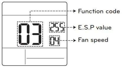
[Select fan speed]
E.S.P value : 000~255
01 : Slow
02 : Low
03 : Middle
04 : High
05 : Power
![]() Press
Press ![]() button to select fan speed or
button to select fan speed or
E.S.P value.
![]() NOTE
NOTE
- Please be careful when adjusting ESP values.
- It does not work to setup ESP value for slow/power step for some products.
- ESP value range is dependent on product.
Temperature sensor setting (Code 4)
Determines if you will use the indoor unit mounted sensor or the remote controller sensor.
<Thermistor table>
| Temperature sensor selection | Function | ||
| 1 | Thermostat | Operate according to thermostat temperature sensor | |
| 2 | Indoor unit | Operate according to indoor unit temperature sensor | |
| 3 | 2TH | Cooling | Operate according to higher temperature by comparing indoor unit’s and thermostat’s temperature. (There are products that operate at a lower temperature.) |
| Heating | Operate according to lower temperature by comparing indoor unit’s and thermostat’s temperature. | ||
![]() The function of 2TH has different operation characteristics according to the product.
The function of 2TH has different operation characteristics according to the product.
Ceiling height (Code 5)
Controls the fan speed stage according to the ceiling height in the ceiling type product.
<Ceiling height selection table>
| Ceiling height level | Description | |
| 1 | Low | Decrease the indoor airflow rate 1 step from standard level |
| 2 | Standard | Set the indoor airflow rate as standard level |
| 3 | High | Increase indoor airflow rate 1 step from standard level |
| 4 | Very High | Increase indoor airflow rate 2 steps from standard level |
![]() Ceiling height setting is only available for some products.
Ceiling height setting is only available for some products.
![]() Ceiling height of ‘Very high’ function may not exist depending on the indoor unit.
Ceiling height of ‘Very high’ function may not exist depending on the indoor unit.
![]() Refer to the product manual for more details.
Refer to the product manual for more details.
Static pressure (Code 6)
Static pressure setting can be set only in the duct products. (It cannot be set in other products.)
<Static pressure setting table>
| Pressure selection | Function | ||
| Zone state | ESP standard value | ||
| 1 | V-H | Variable | High |
| 2 | F-H | Fixed | High |
| 3 | V-L | Variable | Low |
| 4 | F-L | Fixed | Low |
Override master/slave setting (Code 8)
The operation master / slave selection function is to avoid other mode operations, and it is the function to prevent the selection of opposite mode of the indoor unit master by the indoor units set as slaves.
| M/S | Description | |
| 1 | Master | Using group control, this master sets the mode of slave IDU’s. |
| 2 | Slave | For the indoor unit set as slave, it can only select the some operation mode of the master indoor unit cycle. Ex) Master is in cooling cycle, slave can select cooling, dehumidification, auto, and wind only. Master is in heating cycle, slave can select auto, heating, and wind only. |
![]() NOTE
NOTE
• Override M/S setting function is only available in some products.
Dry contact mode setting (Code 9)
Dry contact function is the function that can be used only when the dry contact devices is separately purchased and installed.
![]() NOTE
NOTE
- For dry contact mode related detail functions, refer to the individual dry contact manual.
- What is dry contact?
- It means the contact point signal input when the hotel card key, human body detection sensor, etc. are interfacing with the air conditioner.
- Added system functionality by using external inputs (dry contacts and wet contacts).
Heating thermal on/off setting (Code 15)
You can adjust the heating on/off temperature according to the field environment in preparation for over heating or heating claim.
| Value | Thermal on | Thermal off |
| 0 | Default(Different from each product) | |
| 1 | 8°F(4°C) | 1 2°F(6°C) |
| 2 | 4°F(2°C) | 8°F(4°C) |
| 3 | -2°F(-1°C) | 2°F(1°C) |
| 4 | -1°F(-0.5°C) | 1 °F(0.5°C) |
Emergency heater setting (Code 18)
This function is only available on some products.
This function will set the emergency heater setting.
Emergency heater is used to heat the space in emergency cases such as heat pump error.
Emergency heat is in place of and does not supplement heat pump.
![]() Emergency heater setting function sets following conditions:
Emergency heater setting function sets following conditions:
- Emergency heater operation while in error or outdoor unit operating in the cooling cycle.
- Emergency heater operation in low outdoor ambient temperature.
- Fan speed setting during emergency heater operation.
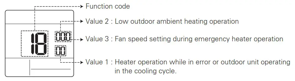 Press button to value 1, value 2 or value 3.
Value 1
18:00 : Disable emergency heater (Default)
18:01 : Enable emergency heater
When it connect general function indoor unit
| Value 2 | Enable temperature | Disable temperature | ||
| Fahrenheit (°F) | Celsius (°C) | Fahrenheit (°F) | Celsius (°C) | |
| 0 | Not used(Default) | |||
| 1 | 0°F | -18°C | 5°F | -15°C |
| 2 | 5°F | -15°C | 10°F | -12°C |
| 3 | 10°F | -12°C | 15°F | -9°C |
When it connect extended function indoor unit
| Value 2 | Enable temperature | Disable temperature | ||
| Fahrenheit (°F) | Celsius (°C) | Fahrenheit (°F) | Celsius (°C) | |
| 0 | Not used(Default) | |||
| 1 | -10°F | -23°C | -5°F | -20°C |
| 2 | -5°F | -21°C | 0°F | -17°C |
| 3 | 0°F | -18°C | 5°F | -14°C |
| 4 | 5°F | -15°C | 10°F | -11°C |
| 5 | 10°F | -12°C | 15°F | -8°C |
| 6 | 15°F | -9°C | 20°F | -5°C |
| 7 | 20°F | -7°C | 25°F | -2°C |
| 8 | 25°F | -4°C | 30°F | 1°C |
| 9 | 30°F | -1°C | 35°F | 4°C |
| 10 | 35°F | 2°C | 40°F | 7°C |
| 11 | 40°F | 4°C | 45°F | 10°C |
| 12 | 45°F | 7°C | 50°F | 13°C |
| 13 | 50°F | 10°C | 55°F | 16°C |
| 14 | 55°F | 13°C | 60°F | 19°C |
| 15 | 60°F | 16°C | 65°F | 22°C |
Value 3
0 : Fan off
1 : Fan on (Fan is off when heater is off)
Check indoor unit address number (Code 26)
It is the function to verify the indoor unit address designated by the outdoor unit.
Cooling thermal on/off setting (Code 27)
It can adjust the cooling thermal on/off temperature according to the field environment in preparation for over cooling or cooling claim.
![]() CAUTION
CAUTION
This function setting must be carried out by a certified technician.
| Value | Thermal on | Thermal off |
| 0 | 1°F(0.5°C) | -1°F(-0.5°C) |
| 1 | 12°F(6°C) | 8°F(4°C) |
| 2 | 8°F(4°C) | 4°F(2°C) |
| 3 | 2°F(1°C) | -2°F(-1°C) |
Setting temperature range (Code 31)
This function is used to select the temperature range options.
Value 00 (Default)
• Cooling : 64~86°F(18~30°C)
• Heating : 60~86°F(16~30°C)
Value 01
• Cooling : 64~99°F(18~37.5°C)
• Heating : 40~86°F(4~30°C)
![]() NOTE
NOTE
- In case of the setting expanded temperature range (set), please note that the setting of the wired remote controller can be altered under below circumstances.
- In case of cooling at 87~99°F(30.5~37.5°C), it is changed to cooling at 86°F(30°C).
- In case of heating at 40~59°F(4~15.5°C), it is changed to heating at 60°F(16°C).
- If set on dual set points, it is changed to the current operation mode(cooling or heating) of the indoor unit.
Static pressure step (Code 32)
This is the function that static pressure of the product is divided in 11 steps for setting.
00 : Use static pressure(code 06) set value
01~ 11 : Use static pressure step (code 32) set value
![]() Refer to the product manual for information on each step value.
Refer to the product manual for information on each step value.
![]() This function is applied to only duct type.
This function is applied to only duct type.
![]() Setting this in other cases will cause malfunction.
Setting this in other cases will cause malfunction.
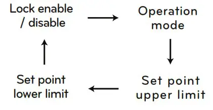
Set point range lock (Code 34)
It is the function that can limit the range of the desired temperature that can be set in the wired remote controller.
When the temperature range is locked, the desired temperature can be set only in the range of the set value. But, the desired temperature value by central control unit or additional accessories reflects the desired temperature received beyond the range.
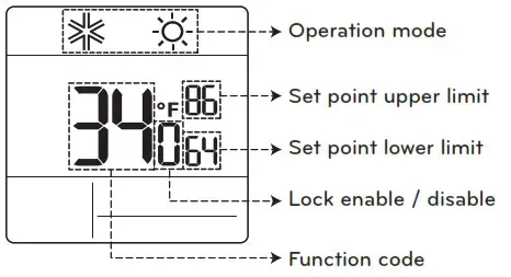
![]() Press
Press ![]() button to select each function like below.
button to select each function like below.
| Indoor unit control method | Code 31 | Cooling | Heating |
| Single set point | 0 | 64-86 °F (1830 °C) | 60-86 °F (1630 °C) |
| 1 | 64-99 °F (1837.5 °C) | 40-86 °F (4-30 °C) | |
| Dual set points | 50-99 °F (10-37.5 °C) | 40-90 °F (4-32 °C) |
CN_EXT (Code 52)
It is the function to set a purpose of digital input port(CN_EXT) of indoor unit PCB.
| Value | Description |
| 0 | Use installer code No. 41 setting value (simple dry contact setting value) |
| 1 | Simple operation on/off |
| 2 | Simple dry contact (It takes HL when operation is off.) |
| 3 | Indoor unit single emergency stop |
| 4 | Occupied / unoccupied |
| 5 | Indoor unit all emergency stop It can be set only when there is indoor unit emergency stop function. |
| 6 | Window contact |
| 7 | Window contact lock |
Outdoor unit cycle priority (Code 56)
It is the function to clear the limit and set the operation mode when it is cleared, to be able to select the operation mode opposite to the operation mode of the outdoor unit currently in operation while the connected product is in
Slave mode.
![]() When you set installer code 08:00 (operation slave), according to the operation status of the outdoor unit, cooling/heating mode selection is restricted.
When you set installer code 08:00 (operation slave), according to the operation status of the outdoor unit, cooling/heating mode selection is restricted.
Value 1 00 : Not use
- According to the outdoor unit operation mode, operation mode selection is limited.
The following operation modes can be selected according to the outdoor unit cycle. - Cooling cycle: auto, fan, cool, dehumidification
- Heating cycle: auto, fan, heat
Value 1 01 : Standby
- In case of the operation mode opposite to the outdoor unit operation mode, it maintains the current operation mode. At this time, it maintains thermal off + fan off state.
Value 1 02 : Cool
- Outdoor unit operation has priority in cooling operation. It is the function to enable the heating operation by heater in the product in heating operation.
For heater interface operation, set ‘emergency heater setting’ and ‘auxiliary heater’. - Emergency heater setting – installer code 18
- Auxiliary heater – installer code 25
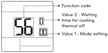
![]() Press
Press ![]() button to select value 1 or value 2.
button to select value 1 or value 2.
| Value 2 | Waiting time for cooling thermal off |
| 0 | 45 minutes (default) |
| 1 | 30 minutes |
| 2 | 60 minutes |
| 3 | 90 minutes |
| 4 | 120 minutes |
| 5 | Not use |
Outdoor temperature for heating stages (Code 57)
It is a function that sets outdoor temperature values for two stages heating. If user sets outdoor temperature T1 and △T, indoor unit will select heating stage between indoor unit operation and heater operation.
![]() When the emergency heater setting is set (installer code 18), emergency heater control operation is performed with priority.
When the emergency heater setting is set (installer code 18), emergency heater control operation is performed with priority.
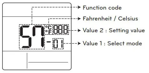
![]() Press
Press ![]() button to select value 1 or value 2.
button to select value 1 or value 2.
| Value 1 | Select mode |
| 1 | Use/Not use setting |
| 2 | T1 value setting |
| 3 | △T value setting |
Value 1 : 01
| Setting value | Description |
| 0 | Not use |
| 1 | Use |
Value 1 : 02
| Temperature unit | Temperature unit |
| Celsius | Celsius |
| Fahreneit | Fahreneit |
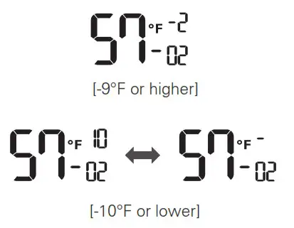
Value 1 : 03
| Temperature unit | △T setting range |
| Celsius | 0~35°C |
| Fahreneit | 0~70°F |
Operation according to T1, △T setting and outdoor temperature.
① (T1 +△T < Outdoor temperature) : only heat pump used
② (T1 < Outdoor temperature < T1 + △T) : both heater and heat pump used
③ (Outdoor temperature < T1) : only heater used
Fan setting during thermal off (Occupancy / Operation mode) (Code 67)
Set the fan speed opreation during thermal off condition according to occupancy and operation mode.
| <Select mode> | <Step> |
| 00: Cooling / Occupied | 00 : Not used |
| 01: Cooling / Unoccupied | 01 : Fan low |
| 02: Heating / Occupied | 02 : Previous fan setting |
| 03: Heating / Unoccupied | 03 : Fan off |
Auto ESP (Code 68)
This function automatically sets the rotation speed of the fans corresponding to each step of rated airflow for easy installation.
| < Mode > | < Manual step > |
| 00: Not use 01: Auto 02: Manual 03: Pass 04: Fail |
00: 190 V 01: 200 V 02: 210 V 03: 220 V 04: 230 V 05: 240 V 06: 250 V 07: 260 V 08: 270 V |
![]() The voltage can be set by setting the Auto ESP Mode to ‘Manual (02)’, then pressing the `Fanspeed` button.
The voltage can be set by setting the Auto ESP Mode to ‘Manual (02)’, then pressing the `Fanspeed` button.
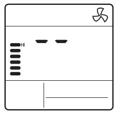
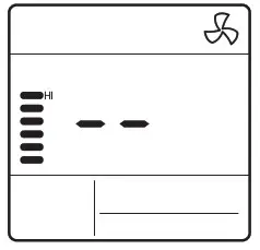
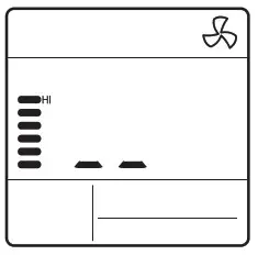
![]() While ‘Auto ESP’ is being set, the display on the wired remote control changes as shown below, and the wired remote control cannot be operated.
While ‘Auto ESP’ is being set, the display on the wired remote control changes as shown below, and the wired remote control cannot be operated.
![]() Once the set-up is complete, you can enter installer setup (68) to check whether the set-up has succeeded or failed. (03: Success, 04: Failure)
Once the set-up is complete, you can enter installer setup (68) to check whether the set-up has succeeded or failed. (03: Success, 04: Failure)
 |
 |
 |
![]()
LG Electronics Inc.
Manufacturer: LG Electronics Inc.
Changwon 2nd factory, 84, Wanam-ro,
Seongsan-gu, Changwon-si, Gyeongsangnam-do, KOREA