door opener on a one-piece door. The Timer-to-Close is to be used ONLY with sectional doors.
Important Safety Instructions
Safety Symbol and Signal Word Review
This garage door opener has been designed and tested to offer safe service provided it is installed, operated, maintained and tested in strict accordance with the instructions and warnings contained in this manual.
When you see these Safety Symbols and Signal Words on the following pages, they will alert you to the possibility of serious injury or death if you do not comply with the warnings that accompany them.
The hazard may come from something mechanical or from electric shock. Read the warnings carefully.
![]()
Warning Mechanical

Warning Electrical
When you see this Signal Word on the following pages, it will alert you to the possibility of damage to your garage door and/or the garage door opener if you do not comply with the cautionary statements that accompany it. Read them carefully.
IMPORTANT INSTALLATION INSTRUCTIONS
To reduce the risk of SEVERE INJURY or DEATH:
- READ AND FOLLOW ALL WARNINGS AND INSTRUCTIONS.
- Install garage door opener ONLY on properly balanced and lubricated garage door. An improperly balanced door may NOT reverse when required and could result in SEVERE INJURY or DEATH.
- ALL repairs to cables, spring assemblies and other hardware MUST be made by a trained door systems technician BEFORE installing opener.
- Disable ALL locks and remove ALL ropes connected to garage door BEFORE installing opener to avoid entanglement.
- Install garage door opener 7 feet (2.13 m) or more above fl oor.
- Mount the emergency release within reach, but at least 6 feet (1.83 m) above the fl oor and avoiding contact with vehicles to avoid accidental release.
- NEVER connect garage door opener to power source until instructed to do so.
- NEVER wear watches, rings or loose clothing while installing or servicing opener. They could be caught in garage door or opener mechanisms.
- Install wall-mounted garage door control:
• within sight of the garage door.
• out of reach of children at minimum height of 5 feet (1.5 m).
• away from ALL moving parts of the door. - Place entrapment warning label on wall next to garage door control.
- Place manual release/safety reverse test label in plain view on inside of garage door.
- Upon completion of installation, test safety reversal system. Door MUST reverse on contact with a 1-1/2″ (3.8 cm) high object (or a 2×4 laid fl at) on the fl oor.
- To avoid SERIOUS PERSONAL INJURY or DEATH from electrocution, disconnect ALL electric and battery power BEFORE performing ANY service or maintenance.
- DO NOT enable the Timer-to-Close functionality if operating either one-piece or swinging garage doors. To be enabled ONLY when operating a sectional door.
- SAVE THESE INSTRUCTIONS.
Operation
Your garage door opener is equipped with features to provide you with greater control over your garage door operation. Accessories provided with your garage door opener will vary depending on the garage door opener model purchased.
ALERT2CLOSE
The Alert2Close feature provides a visual and an audible alert that an unattended door is closing.
TIMER-TO-CLOSE (TTC)
The Timer-to-Close feature automatically closes the door after a specifi ed time period that can be adjusted using a TTC enabled door control (Models 881LM or 880LM). Prior to and during the door closing the garage door opener lights will fl ash and the garage door opener will beep.
MyQ™
MyQ™ technology uses a 900MHz signal to provide two-way communication between the garage door opener and MyQ™ enabled accessories. Your garage door opener is compatible with up to 16 MyQ™ accessories.
REMOTE CONTROLS AND DOOR CONTROLS (SECURITY✚2.0™)
Your garage door opener has already been programmed at the factory to operate with your remote control, which changes with each use, randomly accessing over 100 billion new codes. Compatible with MyQ™ and Security✚ 2.0™.
NOTE: Older LiftMaster remote controls, door controls, and third party products are not compatible.
Accessories (Security✚ 2.0™): MEMORY CAPACITY
Remote Controls: Up to 24
Door Controls: Up to 2 Smart Control Panels or 4 of any other Security+ 2.0™ door controls
Keyless Entries: Up to 2
THE PROTECTOR SYSTEM® (SAFETY REVERSING SENSORS)
When properly connected and aligned, the safety reversing sensors will detect an obstruction
in the path of the infrared beam. If an obstruction breaks the infrared beam while the door is
closing, the door will stop and reverse to full open position, and the opener lights will fl ash
10 times. If the door is fully open, and the safety reversing sensors are not installed, or are
misaligned, the door will not close from a remote control. However, you can close the door
if you hold the button on the door control or keyless entry until the door is fully closed. The
safety reversing sensors do not affect the opening cycle.
ENERGY CONSERVATION
For energy effi ciency the garage door opener will enter sleep mode when the door is fully closed. The sleep mode shuts the garage door opener down until activated. The sleep mode is sequenced with the garage door opener light bulb; as the light bulb turns off the sensor LEDs will turn off and whenever the garage door opener lights turn on the sensor LEDs will light.
LIGHTS
The garage door opener light bulbs will turn on when the opener is initially plugged in; power is restored after interruption, or when the garage door opener is activated. The lights will turn off automatically after 4-1/2 minutes. An incandescent A19 light bulb (100 watt maximum) or for maximum energy effi ciency a 26W (100W equivalent) compact fl uorescent light (CFL) bulb may be used.
Light Feature
The garage door opener is equipped with an added feature; the lights will turn on when someone enters through the open garage door and the safety reversing sensor infrared beam is broken. For added control over the light bulbs on your garage door opener.
USING YOUR GARAGE DOOR OPENER
The garage door opener can be activated through a wall-mounted door control, remote control, wireless keyless entry or MyQ™ accessory. When the door is closed and the garage door opener is activated the door will open. If the door senses an obstruction or is interrupted while opening the door will stop. When the door is in any position other than closed and the garage door opener is activated the door will close. If the garage door opener senses an obstruction while closing, the door will reverse. If the obstruction interrupts the sensor beam the garage door opener lights will blink 10 times. However, you can close the door if you hold the button on the door control or keyless entry until the door is fully closed.
The safety reversing sensors do not affect the opening cycle. The safety reversing sensor must be connected and aligned correctly before the garage door opener will move in the down direction.
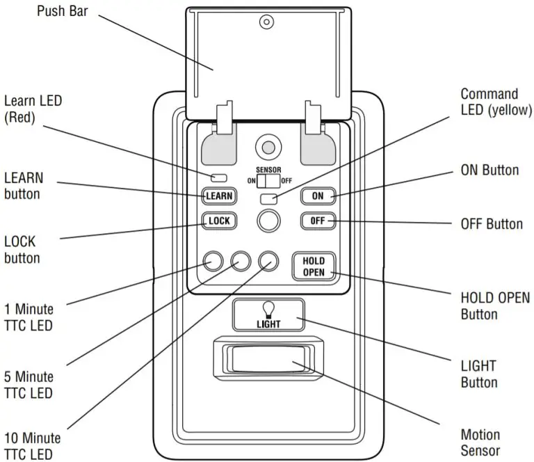
Using the Door Control
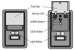
PUSH BAR
Press the push bar to open and close the door.
LIGHT BUTTON
Press the LIGHT button to turn the garage door opener lights on or off. When the lights are turned on they will stay on until the LIGHT button is pressed again, or until the garage door opener is activated. Once the garage door opener is activated the lights will turn off after the specified period of time (the factory setting is 4-1/2 minutes). The LIGHT button will not control the lights when the door is in motion. The duration of the light timing can be adjusted using the door control.
Light Button
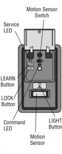
MOTION-DETECTING CONTROL PANEL The following features are accessible by lifting the push bar:
LEARN A DEVICE
Any compatible remote controls, wireless keyless entry, or MyQ™ accessories can be programmed to the garage door opener by pressing the Learn button on the Motion-Detecting Control Panel.
LOCK
The LOCK feature is designed to prevent activation of the garage door opener from remote controls while still allowing activation from the door control and keyless entry. This feature is useful for added peace of mind when the home is empty (i.e. vacation).
AUTOMATIC LIGHT
Motion Sensor
Factory default is set to on. This feature automatically turns on the garage door opener lights when motion is sensed. The lights will come on for the set period of time, then shut off. If using the garage door opener light as a work light disable the motion sensor, otherwise the light will turn off automatically if you are beyond the range of the sensor.
Light Feature
The lights will turn on when someone enters through the open garage door and the safety reversing sensor infrared beam is broken.
MAINTENANCE ALERT SYSTEM (MAS)
This feature assists the homeowner in ensuring the garage door opener system stays in good working condition. When the garage door opener needs to be serviced (approximately 4500 garage door opener cycles) the command (yellow) and service (red) LEDs will begin to alternately flash back and forth. The factory setting for the MAS feature is off and can be activated at the time of installation. Contact your installing dealer for service.
Programming – Motion-Detecting Control Panel
Features
Lock:
NOTE: Your remote controls will NOT work when LOCK mode is active however your keyless entry will still allow access to your garage. Activate: Press and hold the LOCK button for 2 seconds. The command LED will flash as long as the lock feature is activated and your handheld remote control will not operate your door at this time. Deactivate: Press and hold the LOCK button gain for 2 seconds. The command LED will stop flashing and normal operation will resume.
Light:
To change the amount of time the garage door opener lights will stay on:
Press and hold the LOCK button until the garage door opener lights flash.* The time interval is indicated by the number of flashes.
NUMBER OF TIMES GARAGE DOOR OPENER LIGHTS FLASH 1:2:3:4
TIME THE GARAGE DOOR OPENER LIGHT STAYS ON 1 ½ Minutes: 2 ½ Minutes: 3 ½ Minutes: 4 ½ Minutes
To cycle through the time intervals repeat the step above.
Deactivate: Press and hold the LIGHT button until the garage door opener lights turn on, then off again.*
Activate: Start with the garage door opener lights on. Press and hold the LIGHT button until the garage door opener lights turn off, then on again.*
* Approximately 10 seconds
Motion Sensor: Activate/Deactivate: Slide the motion sensor switch ON or OFF.
To Program a Remote Control or Keyless Entry:
- Press the LEARN button on the door control to enter Programming Mode.
- Press the LEARN button again, the LED will fl ash once.
- Remote Control: Press the button on the remote control that you wish to operate your garage door.
Keyless Entry: Enter a 4-digit personal identifi cation number (PIN) of your choice on the keyless entry keypad. Then press the ENTER button.
The garage door opener lights will fl ash (or two clicks will be heard) when the code has been programmed. If programming is unsuccessful, repeat steps 1-3 or program the remote using the learn button on the garage door opener.
Maintenance Alert System (MAS):
Activate/Deactivate
Press and hold the LEARN button. Then press the LIGHT button. The service LED will fl ash the status; Active is 2 fl ashes and deactivated is 3 fl ashes.
Programming – Remote Controls
Your garage door opener has been programmed at the factory to operate with your remote control. Older LiftMaster remote controls are NOT compatible. Programming can be done through the door control or the Learn button on the garage door opener. To program additional remote controls refer to the instructions provided with the additional remote controls or visit www.liftmaster.com. If your vehicle is equipped with a Homelink®, you may require an external adapter depending on the make, model, and year of your vehicle. Visit www.homelink.com for additional information.
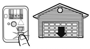
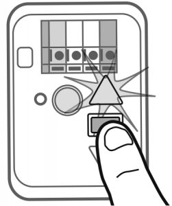
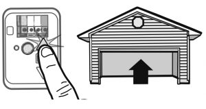
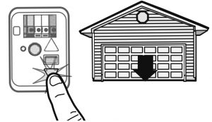
PROGRAM A REMOTE USING THE LEARN BUTTON ON THE GARAGE DOOR OPENER
- Press and release the Learn button on the garage door opener. The Learn indicator light will glow steadily for 30 seconds.
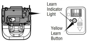
- Within 30 seconds, press and hold the button on the remote control.
- Release the button when the garage door opener light blinks.
It has learned the code. If light bulbs are not installed, two clicks will be heard.
When replacing the light lens cover, ensure the antenna wires are hanging straight down.
ERASE ALL REMOTE CONTROLS AND KEYLESS ENTRIES
- Press and hold the learn button on garage door opener until the learn LED goes out (approximately 6 seconds). All remote control and keyless entry codes are now erased. Reprogram any accessory you wish to use.
ERASE ALL DEVICES
- Press and hold the learn button on garage door opener until the learn LED goes out (approximately 6 seconds).
- Immediately press and hold the learn button again until the learn LED goes out. All codes are now erased. Reprogram any accessory you wish to use.
To Open the Door Manually
![]() WARNING
WARNING
To prevent possible SERIOUS INJURY or DEATH from a falling garage door:
- If possible, use emergency release handle to disengage trolley ONLY when garage door is CLOSED. Weak or broken springs or unbalanced door could result in an open door falling rapidly and/or unexpectedly.
- NEVER use emergency release handle unless garage doorway is clear of persons and obstructions.
- NEVER use handle to pull door open or closed. If rope knot becomes untied, you could fall.
DISCONNECT THE TROLLEY
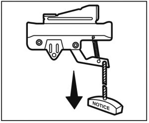
- The door should be fully closed if possible.
- Pull down on the emergency release handle.
RECONNECT THE TROLLEY
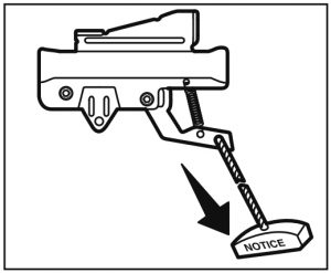
The lockout feature prevents the trolley from reconnecting automatically.
- Pull the emergency release handle down and back (toward the opener). The door can then be raised and lowered manually as often as necessary.
- To disengage the lockout feature, pull the handle straight down.
The trolley will reconnect on the next UP or DOWN operation, either manually or by using the door control or remote control.
Battery Backup (If applicable)
The battery backup system allows access in and out of your garage, even when the power is out. When the garage door opener is operating on battery power, the garage door opener will run slower, the light will not function, the Battery Status LED will glow solid orange, and a beep will sound approximately every 2 seconds.
The battery charges when the garage door opener is plugged into a 110Vac electrical outlet that has power and requires 24 hours to fully charge. A fully charged battery supplies 12Vdc to the garage door opener for one to two days of normal operation during an electrical power outage. After the electrical power has been restored, the battery will recharge within 24 hours. The battery will last approximately 1 to 2 years with normal usage. Instructions for replacement are provided with the battery. To obtain maximum battery life and prevent damage, disconnect the battery when the garage door opener is unplugged for an extended period of time.
NOTE: When the garage door opener is in battery backup mode the garage door opener lights, Timer-to-Close, and Remote Close features are unavailable.
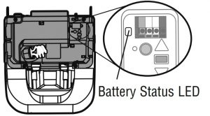
BATTERY STATUS LED
NOTE: The Battery Status LED is most visible with the garage door opener light off.
Battery does not have to be fully charged to operate the garage door opener.
GREEN LED:
All systems are normal.
- A solid green LED light indicates the battery is fully charged.
- A fl ashing green LED indicates the battery is being charged.
ORANGE LED:
The garage door opener has lost power and is in battery backup mode.
- A solid orange LED with beep, sounding approximately every 2 seconds, indicates the garage door opener is operating on battery power.
- A fl ashing orange LED with beep, sounding every 30 seconds, indicates the battery is low.
RED LED:
The garage door opener’s 12V battery needs to be replaced.
- A solid red LED with beep, sounding every 30 seconds, indicates the garage door opener needs servicing. Please call for replacement battery to allow your system to operate during a power outage.
Adjustment
WARNING: Without a properly installed safety reversal system, persons (particularly small children) could be SERIOUSLY INJURED or KILLED by a closing garage door.
- Incorrect adjustment of garage door travel limits will interfere with proper operation of safety reversal system.
- After ANY adjustments are made, the safety reversal system MUST be tested. Door MUST reverse on contact with 1-1/2″ (3.8 cm) high object (or 2×4 laid fl at) on floor.
CAUTION: To prevent damage to vehicles, be sure fully open door provides adequate clearance.
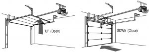
Your garage door opener is designed with electronic controls to make setup and adjustments easy. The adjustments allow you to program where the door will stop in the open (UP) and close (DOWN) position.
The electronic controls sense the amount of force required to open and close the door.
NOTE: If anything interferes with the door’s upward travel it will stop. If anything interferes with the door’s downward travel, it will reverse.
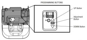
PROGRAMMING BUTTONS
The programming buttons are located on the left side panel of the garage door opener and are used to program the travel.
1. Program the Travel
Without a properly installed safety reversal system, persons (particularly small children) could be SERIOUSLY INJURED or KILLED by a closing garage door.
* Incorrect adjustment of garage door travel limits will interfere with proper operation of safety reversal system.
* After ANY adjustments are made, the safety reversal system MUST be tested. Door MUST reverse on contact with 1-1/2″ (3.8 cm) high object (or 2×4 laid flat) on floor.
1.1 Press and hold the Adjustment Button until the UP Button begins to fl ash and/or a beep is heard.
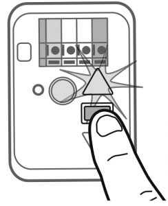
1.2 Press and hold the UP Button until the door is in the desired UP position.
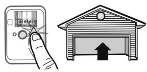
NOTE: The UP and DOWN Buttons can be used to move the door up and down as needed.
1.3 Once the door is in the desired UP position press and release the Adjustment Button. The garage door opener lights will flash twice and the DOWN Button will begin to flash.
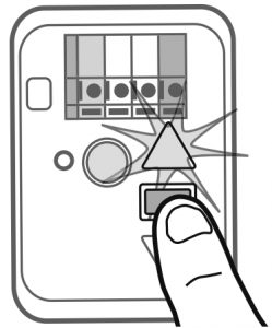
1.4 Press and hold the DOWN Button until the door is in the desired DOWN position.
NOTE: The UP and DOWN Buttons can be used to move the door up and down as needed.
1.5 Once the door is in the desired DOWN position press and release the Adjustment Button. The garage door opener lights will flash twice and the UP Button will begin to flash.
1.6 Press and release the UP Button. When the door travels to the programmed UP position, the DOWN Button will begin to flash.
1.7 Press and release the DOWN Button. The door will travel to the programmed DOWN position. Programming is complete.
* If the garage door opener lights are flashing 5 times during the steps for Program the Travel, the programming has timed out. If the garage door opener lights are fl ashing 10 times during the steps for Program the Travel, the safety reversing sensors are misaligned or obstructed. When the sensors are aligned and unobstructed, cycle the door through a complete up and down cycle using the remote control or the UP and DOWN buttons. Programming is complete. If you are unable to operate the door up and down, repeat the steps for Programming the Travel.
2. Test the Safety Reversal System
![]() WARNING
WARNING
Without a properly installed safety reversal system, persons (particularly small children) could be SERIOUSLY INJURED or KILLED by a closing garage door.
- Safety reversal system MUST be tested every month.
- After ANY adjustments are made, the safety reversal system MUST be tested. Door MUST reverse on contact with 1-1/2″ high (3.8 cm) object (or 2×4 laid flat) on the floor.
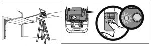
2.1 With the door fully open, place a 1-1/2 inch (3.8 cm) board (or a 2×4 laid flat) on the floor, centered under the garage door.
2.2 Press the remote control push button to close the door. The door MUST reverse when it makes contact with the board.
If the door stops and does not reverse on the obstruction, increase the down travel (refer to Adjustment Step 1).
Repeat the test. When the door reverses upon contact with the 1-1/2 inch board, remove the board and open/close the door 3 or 4 times to test the adjustment.
If the test continues to fail, call a trained door systems technician.
3. Test the Protector System ®
![]() WARNING: Without a properly installed safety reversing sensor, persons (particularly small children) could be SERIOUSLY INJURED or KILLED by a closing garage door.
WARNING: Without a properly installed safety reversing sensor, persons (particularly small children) could be SERIOUSLY INJURED or KILLED by a closing garage door.
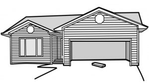
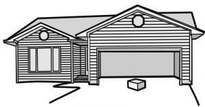
3.1 Open the door. Place the garage door opener carton in the path of the door.
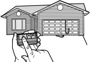
3.2 Press the remote control push button to close the door. The door will not move more than an inch (2.5 cm), and the garage door opener lights will flash 10 times.
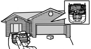
The garage door opener will not close from a remote control if the LED in either safety reversing sensor is off (alerting you to the fact that the sensor is misaligned or obstructed).
If the garage door opener closes the door when the safety reversing sensor is obstructed (and the sensors are no more than 6 inches [15 cm] above the fl oor), call for a trained door systems technician.
Maintenance
EVERY MONTH
- Manually operate door. If it is unbalanced or binding, call a trained door systems technician.
- Check to be sure door opens and closes fully. Adjust if necessary.
- Test the safety reversal system. Adjust if necessary.
EVERY YEAR
- Oil door rollers, bearings and hinges. The garage door opener does not require additional lubrication. Do not grease the door tracks.
- (If applicable) Test the battery backup and consider replacing the battery to ensure the garage door opener will operate during an electrical power outage.
Testing the Battery Backup:
- Unplug the garage door opener. The battery status LED will either glow solid orange indicating opener is operating on battery power or will fl ash indicating low battery power.
- Open and close the door using the remote control or door control.
NOTE: The garage door opener may run slower if the battery is not fully charged. The battery will take 24 hours to fully charge. - Plug in the garage door opener. Verify the battery status LED is fl ashing green, indicating the battery is charging.
EVERY TWO TO THREE YEARS
- Use a rag to wipe away the existing grease from the garage door opener rail. Reapply a small layer of white lithium grease to the top and underside of the rail surface where the trolley slides.
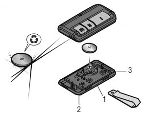
The Remote Control Battery
WARNING: To prevent possible SERIOUS INJURY or DEATH:
- NEVER allow small children near batteries.
- If the battery is swallowed, immediately notify a doctor.
To reduce risk of fire, explosion or chemical burn:
- Replace ONLY with 3V2032 coin batteries.
- DO NOT recharge, disassemble, heat above 212°F (100°C) or incinerate.
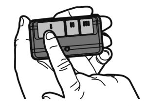
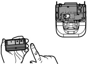
The lithium batteries should produce power for up to 5 years. If the battery is low, the remote control’s LED will not flash when the button is pressed. To replace the battery, pry open the case first in the middle (1), then at each side (2 and 3) with the visor clip. Insert battery positive side up.
Replace the batteries with only 3V2032 coin cell batteries. Dispose of old batteries properly.
NOTICE: To comply with FCC and/or Industry Canada (IC) rules, adjustment or modifications of this transceiver are prohibited. THERE ARE NO USER SERVICEABLE PARTS. Any changes or modifications not expressly approved by the party responsible for compliance could void the user’s authority to operate the equipment.
This device complies with Part 15 of the FCC rules and IC RSS-210. Operation is subject to the following two conditions:
(1) this device may not cause harmful interference, and (2) this device must accept any interference received, including interference that may cause undesired operation.
This Class B digital apparatus complies with Canadian ICES-003.
Troubleshooting
Diagnostic Chart
Your garage door opener is programmed with self-diagnostic capabilities. The UP and DOWN arrows on the garage door opener will fl ash the diagnostic codes.
DIAGNOSTIC CODE:
SYMPTOM:
SOLUTION
Up arrow Flash(es); Down arrow Flash(es)
1; 1: The garage door opener will not close and the light bulbs flash.:
Safety sensors are not installed, connected, or wires may be cut. Inspect sensor wires for a disconnected or cut wire.
1; 2:
The garage door opener will not close and the light bulbs flash.
There is a short or reversed wire for the safety sensors. Inspect safety sensor wire at all staple and connection points, replace wire or correct as needed.
1; 3:
The door control will not function.:
The wires for the door control are shorted or the door control is faulty. Inspect door control wires at all staple and connection points, replace wire or correct as needed.
1; 4:
The garage door opener will not close and the light bulbs flash.:
Safety sensors are misaligned or were momentarily obstructed. Realign both sensors to ensure both LEDs are steady and not fl ickering. Make sure nothing is hanging or mounted on the door that would interrupt the sensor’s path while closing;.
1; 5:
Door moves 6-8″ stops or reverses.:
Manually open and close the door. Check for binding or obstructions, such as a broken spring or door lock, correct as needed. Check wiring connections at travel module and at the logic board. Replace travel module if necessary.
No movement, only a single click.:
Manually open and close the door. Check for binding or obstructions, such as a broken spring or door lock, correct as needed. Replace logic board if necessary.:
Opener hums for 1-2 seconds no movement.:
Manually open and close the door. Check for binding or obstructions, such as a broken spring or door lock, correct as needed. Replace motor if necessary.
1; 6:
Door coasts after it has come to a complete stop.:
Program travel to coasting position or have door balanced by a trained door systems technician.
2; 1-5:
No movement, or sound.:
Replace logic board.
3; 2:
Unable to set the travel or retain position.
Check travel module for proper assembly, replace if necessary.
3; 3:
The battery status LED* is constantly fl ashing green.:
Battery backup* charging circuit error, replace the logic board.
*If applicable.
4; 1-4:
Door is moving stops or reverses.:
Manually open and close the door. Check for binding or obstructions, such as a broken spring or door lock, correct as needed. If the door is binding or sticking contact a trained door systems technician. If door is not binding or sticking attempt to reprogram travel.
4; 5:
Opener runs approximately 6-8″, stops and reverses.:
Communication error to travel module. Check travel module connections, replace travel module if necessary.
4; 6:
The garage door opener will not close and the light bulbs flash.:
Safety sensors are misaligned or were momentarily obstructed. Realign both sensors to ensure both LEDs are steady and not fl ickering. Make sure nothing is hanging or mounted on the door that would interrupt the sensor’s path while closing.
My garage door opener beeps:
The garage door opener can beep for several reasons:
- Garage door opener has been activated through a device or feature such as Timer-to-Close, garage door monitor or LiftMaster Internet Gateway.
- Operating on battery power or the 12Vdc battery needs to be replaced (if applicable).
My remote control will not activate the garage door:
- Verify the lock feature is not activated on the door control.
- Reprogram the remote control.
- If the remote control will still not activate the door check the diagnostic codes to ensure the garage door opener is working properly.
My door will not close and the light bulbs blink on my motor unit:
The safety reversing sensor must be connected and aligned correctly before the garage door opener will move in the down direction.
- Verify the safety sensors are properly installed, aligned and free of any obstructions.
My garage door opener light(s) will not turn off when the door is open:
The garage door opener is equipped with a feature that turns the light on when the safety reversing sensors have been obstructed or when the motion sensor on the door control detects movement in the garage. These features can be disabled using the door control.
My neighbor’s remote control opens my garage door:
Erase the memory from your garage door opener and reprogram the remote control(s).
My vehicle’s Homelink® is not programming to my garage door opener:
Depending on the make, model, and year of your vehicle an external adapter may be required. Visit www.homelink.com for additional information.
Repair Parts
NOTE: For additional parts not shown, visit www.liftmaster.com to download or print the full owner’s manual.
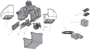
DESCRIPTION: PART NUMBER
1 Light Lens: 41A7562
2 Receiver Logic Board – Model 8350 & 8360: 45DCT
Receiver Logic Board – Model 8355 & 8365: 45ACT
3A Travel Module – Model 8350 & 8360: 41A7114-7
3B Travel Module – Model 8355 & 8365: 41D7742-7
4A Motor w/Travel Module – Model 8350 & 8360: 41D1739-1
4B Motor w/Travel Module – Model 8355: 41D7442
4C Motor w/Travel Module – Model 8365: 41D7440
5 3V2032 Lithium Battery (Remote Control): 10A20
6 Backup Battery (if applicable): 485LM
7 Safety Sensor Kit with receiving and sending sensors with 3 feet (.9 m) 2-conductor wire: 41A5034
Warranty
LIFTMASTER® ONE YEAR LIMITED WARRANTY LIFETIME MOTOR AND BELT* LIMITED WARRANTY ONE YEAR LIMITED WARRANTY FOR THE BATTERY BACKUP SYSTEM*
The Chamberlain Group, Inc. (“Seller”) warrants to the first retail purchaser of this product, for the residence in which this product is originally installed, that it is free from defects in materials and/or workmanship for a period of one year from the date of purchase, except that the motor and belt* are warranted to be free from defects in materials and/or workmanship for the lifetime of the product while you own your residence, and the Battery Backup System* is warranted to be free from defects in materials and/or workmanship for a period of one year from the date of purchase. The proper operation of this product is dependent on your compliance with the instructions regarding installation, operation, and maintenance and testing. Failure to comply strictly with those instructions will void this limited warranty in its entirety.
If, during the limited warranty period, this product appears to contain a defect covered by this limited warranty, call 1-800-528-9131, toll free, before dismantling this product. You will be advised of disassembly and shipping instructions when you call. Then send the product or component, pre-paid and insured, as directed to our service center for warranty repair. Please include a brief description of the problem and a dated proof-of purchase receipt with any product returned for warranty repair. Products returned to Seller for warranty repair, which upon receipt by Seller are confirmed to be defective and covered by this limited warranty, will be repaired or replaced (at Seller’s sole option) at no cost to you and returned pre- paid. Defective parts will be repaired or replaced with new or factory-rebuilt parts at Seller’s sole option. [You are responsible for any costs incurred in removing and/or reinstalling the product or any component.]
ALL IMPLIED WARRANTIES FOR THE PRODUCT, INCLUDING BUT NOT LIMITED TO ANY IMPLIED WARRANTIES OF MERCHANTABILITY AND FITNESS FOR A PARTICULAR PURPOSE, ARE LIMITED IN DURATION TO THE APPLICABLE LIMITED WARRANTY PERIOD SET FORTH ABOVE FOR THE RELATED COMPONENT(S), AND NO IMPLIED WARRANTIES WILL EXIST OR APPLY AFTER SUCH PERIOD. Some states do not allow limitations on how long an implied warranty lasts, so the above limitation may not apply to you. THIS LIMITED WARRANTY DOES NOT COVER NON DEFECT DAMAGE, DAMAGE CAUSED BY IMPROPER INSTALLATION, OPERATION OR CARE (INCLUDING, BUT NOT LIMITED TO ABUSE, MISUSE, FAILURE TO PROVIDE REASONABLE AND NECESSARY MAINTENANCE, UNAUTHORIZED REPAIRS OR ANY ALTERATIONS TO THIS PRODUCT), LABOR CHARGES FOR REINSTALLING A REPAIRED OR REPLACED UNIT, REPLACEMENT OF CONSUMABLE ITEMS (E.G., BATTERIES IN REMOTE CONTROL TRANSMITTERS AND LIGHT BULBS), OR UNITS INSTALLED FOR NON RESIDENTIAL USE. THIS LIMITED WARRANTY DOES NOT COVER ANY PROBLEMS WITH, OR RELATING TO, THE GARAGE DOOR OR GARAGE DOOR HARDWARE, INCLUDING BUT NOT LIMITED TO THE DOOR SPRINGS, DOOR ROLLERS, DOOR ALIGNMENT OR HINGES. THIS LIMITED WARRANTY ALSO DOES NOT COVER ANY PROBLEMS CAUSED BY INTERFERENCE. UNDER NO CIRCUMSTANCES SHALL SELLER BE LIABLE FOR CONSEQUENTIAL, INCIDENTAL OR SPECIAL DAMAGES ARISING IN CONNECTION WITH USE, OR INABILITY TO USE, THIS PRODUCT. IN NO EVENT SHALL SELLER’S LIABILITY FOR BREACH OF WARRANTY, BREACH OF CONTRACT, NEGLIGENCE OR STRICT LIABILITY EXCEED THE COST OF THE PRODUCT COVERED HEREBY. NO PERSON IS AUTHORIZED TO ASSUME FOR US ANY OTHER LIABILITY IN CONNECTION WITH THE SALE OF THIS PRODUCT.
Some states do not allow the exclusion or limitation of consequential, incidental or special damages, so the above limitation or exclusion may not apply to you. This limited warranty gives you specific legal rights, and you may also have other rights, which vary from state to state.
]]>LiftMaster Wireless Keyless Entry 878MAX
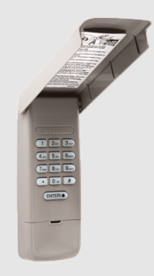
LiftMaster Wireless Keyless Entry 878MAX
BEFORE YOU START Your wireless keyless entry is compatible with 315 MHz or 390 MHz garage door openers manufactured starting January 1, 1993, and have a LEARN button.
Read instructions thoroughly BEFORE beginning. If you are using this product with residential door openers, this product must be used only with door openers manufactured starting January 1, 1993, that use photoelectric sensors located near the bottom of the door track.
IMPORTANT: The keypad will activate your door or gate during programming. Be sure the door is clear of ALL obstructions. Start with the garage door closed. Make sure the garage door opener has a working light because it is a programming indicator.
Install the battery and program the wireless keyless entry prior to installation.
 WARNING: This product can expose you to chemicals including lead, which is known to the State of California to cause cancer or birth defects or other reproductive harm. For more information go to www.P65Warnings.ca.gov
 WARNING
To prevent possible SERIOUS INJURY or DEATH from a moving gate or garage door:
- Install Wireless Keyless Entry within sight of the garage door, out of reach of children at a minimum height of 5feet (1.5 m), and away from ALL moving parts of the door.
- ALWAYS keep remote controls out of reach of children. NEVER permit children to operate, or play with remote controls.
- Activate gate or door ONLY when it can be seen clearly, is properly adjusted, and there are no obstructions to door travel.
ALWAYS keep gate or garage door in sight until completely closed. NEVER permit anyone to cross the path of the moving gate or door.
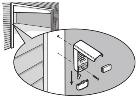
INSTALLATION
- Select a location to mount the wireless keyless entry at a minimum height of 5′ (1.5 m) out of the reach of children.
- Remove the battery cover and battery to show mounting
- Mark the top mounting hole and drill l/8′ (3.2mm) pilot
- Install the top screw, allowing 1/W (3.2mm) to protrude above the surface. Position the wireless keyless entry over the top screw.
- Mark the bottom hole and drill 1/W (3.2 mm) pilot hole. Install the bottom Do not overtighten to avoid cracking the plastic housing.
- Reinstall the battery and replace the cover.
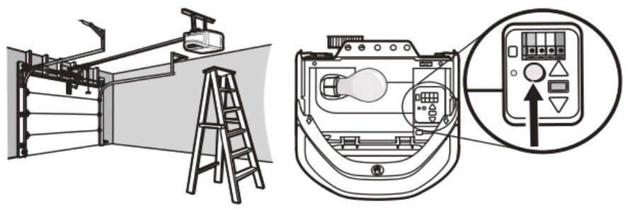
PROGRAM THE INITIAL PIN
The wireless keyless entry is pre-programmed to work with a LiftMaster garage door opener with a yellow LEARN button. Locate the LEARN button on the garage door opener. If the LEARN button is YELLOW, see Method A. Otherwise, see Method B for other colored LEARN buttons.
Method A – Yellow LEARN Button
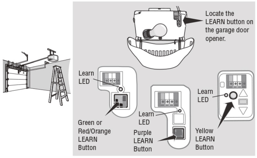
- Press and release the LEARN button on the garage door opener. The learn LED will light.
- Enter a 4-digit personal identification number (PIN) of your choice.
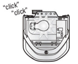
- Press the ENTER button until the opener light bulb blinks or two clicks are heard.
- Test by pressing in the PIN you just programmed, and then press the ENTER The garage door opener will activate.
Method B – Yellow LEARN/Security+ 2.08 and Other LEARN Buttons
- Press and hold the * and # buttons until the lights on the keypad stop blinking.
- Enter a 4-digit personal identification number (PIN) of your choice. Then press the # button. You will use this PIN in step 6.
- Press and release the ENTER button the number of times that corresponds with the garage door opener type:
- Press and release the 0 buttons.
# of Presses Garage Door Opener Type 1 Yellow LEARN Button (Security+ 2.00) 2 Purple LEARN Button (315 MHz Security+0) 3 Red/Orange LEARN Button (390 MHz Security+0) 4 Green LEARN (390 MHz Billion Code) - Press and releas the LEARN button one time on the garage door opener. The Learn LED will light.
- Enter the 4-digit PIN from step 2, then press and release the ENTER button until the garage door opener lights flash or two clicks are heard.
- Test by pressing in the PIN you just programmed, and then press the ENTER button. The garage door opener will activate. Add more openers by repeating steps 1 through 7 using a new PIN for each.
HOW TO USE THE WIRELESS KEYLESS ENTRY
The garage door opener activates when you press the personal identification number (PIN) and ENTER button. The keypad will blink for 15 seconds. During that time the ENTER button can be used to stop, start or reverse the door.
If the wrong PIN number is accidentally pressed, press the correct PIN then ENTER button. The wireless keyless entry will transmit only the last four digits that were pressed before the ENTER button.
ONE BUTTON CLOSE FEATURE: This feature allows you to CLOSE your garage door by pressing just the ENTER button instead of your 4-digit PIN.
NOTE: This feature ONLY closes and is not available on garage door openers manufactured prior to 2006 or an external receiver.
To deactivate the one-button close feature:
- Press and hold the 1 and 9 buttons for 10 seconds. The keypad will blink four times when the one-button close feature is deactivated.
To activate the one button close feature:
- Press and hold the 1 and 9 buttons for 10 seconds. The keypad will blink twice when the one-button close feature is actuated.
PROGRAM A TEMPORARY PIN
NOTE: This feature is not available on garage door openers that have a green LEARN button or an external receiver.
A temporary 4-digit personal identification number (PIN) can be programmed to allow access to visitors. Each programmed PIN can program one temporary PIN. The temporary PIN can be set for a number of hours or a number of door openings. The temporary PIN cannot be the same as any previously programmed PIN.
- Press any programmed PIN, then press and hold the * button until the garage door opener light blinks three times.
- Press the temporary 4-digit PIN of your choice, then press the ENTER button. The light blinks 4 times.
- Enter the temporary PIN limit of use by:
| Number of Hours PIN Will Work | Number of Openings PIN Will Work | |
| Press the number of hours the temporary PIN will work (up to255), then press the * button. The opener light blinks once. | OR | Press the number of openings the temporary PIN will work ( up to 255), then press the # button. The opener light blinks once. |
- Test by pressing in the temporary P N you just programmed, and then press the ENTER button. The garage door opener activates. The test uses up one Clear the temporary PIN by repeating steps 1 through 4, and set the number of hours or openings to 0 at step 3.
CHANGE AN EXISTING PIN*
- Enter the programmed PIN you want to change.
- Press and hold the # button until the garage door opener light blinks twice.
- Enter the new 4-digit PIN of your choice and press the ENTER button. The opener light will blink once.
- Test by entering the PIN you just programmed, and then press the ENTER The garage door opener will activate.
*You cannot change an existing PIN for an opener with a green LEARN button or an external receiver. You MUST repeat ‘Program the Initial PIN’ to change the PIN number.
ERASE ALL REMOTE CONTROL AND KEYLESS ENTRY PROGRAMMING FROM THE OPENER
The following steps will erase ALL remote controls and any keyless entries from your opener.
- Press and hold the LEARN button on the garage door opener until the Learn LED turns off (approximately 6 seconds).
- Test by pressing the buttons on the remote control and keyless entry to ensure they no longer activate the opener.
- Follow programming steps to reprogram each remote control and keyless entry you wish to use.
For more information and support, go to: support.chamberlaingroup.com.
REPLACE THE BATTERY
WARNING
To prevent possible SERIOUS INJURY or DEATH:
- NEVER allow small children near batteries.
- If the battery is swallowed, immediately notify the doctor.
Replace the battery when the keypad becomes dim or does not light after a button is pressed. Slide the cover-up, remove the battery cover, and replace the battery. Dispose of the old battery properly.
ONE YEAR LIMITED WARRANTY
The Chamberlain Group, Inc. warrants to the first consumer purchaser of this product that it is free from defects in materials and/or workmanship for a period of 1 year from the date of purchase.
NOTICE: This device complies With part 15 of the FCC rules and Innovation, Science and Economic Development Canada license-exempt RSS. Operation is subject to the following two conditions: (1) this device may not cause harmful interference, and (2) this device must accept any interference received, including interference that may cause undesired operation.
My changes or modifications not expressly approved by the party responsible for compliance could void the user’s authority to operate the equipment
This device must be installed to ensure a minimum 20 cm (8 in.) distance is maintained between users/bystander rs and the device.
This device has been tested and –found to comply with the limits for a Class B digital device, pursuant to part 15 of the FCC rules and Industry Canada ICES standard. These limits are designed to provide reasonable protection against harmful interference in a residential installation. This equipment generates, uses, and can radiate radio frequency energy and, it not installed and used in accordance with the instructions may cause harmful interference to radio communications. However, there is no guarantee that interference will not occur in a particular installation. If this equipment does cause harmful interference to radio or television reception, which can be determined by turning the equipment of and on, the user is encouraged to try to correct the interference by one or more of the following measures:
- Reorient or relocate the receiving antenna.
- Increase the separation between the equipment and receiver.
- Connect the equipment into an outlet on a circuit different from that to which the receiver is connected.
- Consult the dealer or an experienced radio/technician for help.
For more information, please visit www.devancocanada.com or call toll free at 855-931-3334
HOW TO ORDER REPAIR PARTS
DEVANCO CANADA
19192 HAY ROAD, UNIT Q SUMMERSTOWN, ON K0C 2E0
TOLL-FREE: 855-931-3334
www.devancocanada.com
WHEN ORDERING REPAIR PARTS PLEASE SUPPLY THE FOLLOWING INFORMATION:
√ PART NUMBER
√ DESCRIPTION
√ MODEL NUMBER
How do I program my LiftMaster Wireless Keyless Entry?
LiftMaster Wireless Keyless Entry is programmed by using the Learn Button on the garage door opener. Press and hold the Learn Button for 5 seconds. Release button. The LED will flash rapidly, indicating that it is ready to learn.
Can I use my LiftMaster Wireless Keyless Entry with a LiftMaster garage door opener?
Yes, as long as your garage door opener was manufactured after January 1, 1993.
How many codes can I program on my LiftMaster Wireless Keyless Entry?
You can program up to 4 codes on the LiftMaster Wireless Keyless Entry. Each code can be used to operate one garage door or gate opener.
How do I change the code on my LiftMaster Wireless Keyless Entry?
To change the code, press and hold the Learn Button for 5 seconds. Release button. The LED will flash rapidly, indicating that it is ready to learn. Press and release any button on the keypad to change the code. Repeat until you have entered a new code for each button you want to change. When finished, press and hold any button for 2 seconds to save new code(s). The LED will flash once per second, indicating that it has saved new code(s). If you want to erase all of your codes at once, press and hold any button for 5 seconds until the LED flashes twice per second (approximately 10 seconds). The keypad will then be in programming mode and all codes will be erased when a new code is programmed into any button(s).
Where is the Learn button on my LiftMaster?
Learn buttons that are red, orange, green or purple will be large, square buttons located under the light lens on the back panel of your garage door opener. To program a new garage door remote, press and quickly release your learn button to trigger the machine’s programming mode
How do you program a wireless garage door opener?
Hold the star and hash tag buttons until the lights on the keypad begin to flash. And then stop flashing do not pause longer than five seconds between keystrokes.
What if my garage door opener doesn’t have a Learn button?
If there is no learn button, examine the inside of the old remote by popping the back off of it. If there is a series of small switches, only big enough to be slid one way or another by the end of a pencil, you have a DIP switch unit. Make sure you purchase a universal remote with internal DIP switches
How do I reset my garage door keypad without learning button?
Remove the cover from the garage door opener remote control to reveal the switches within. What is this? Press the * and # pound button at the same time followed by red light blinking a couple of times. Once the blinking light stops the password has been reset
How do I connect to Liftmaster to WiFi?
Inside your garage your wi-fi password. And then you’ll want to enable bluetooth on your phone. And you’ll also need to enable location.
What is yellow button on LiftMaster?
Notes: Openers with a GREEN, RED, ORANGE or PURPLE learn/program button stay in accessory programming mode the 30 seconds, after 30 seconds the learn/program LED will turn off. Units with a YELLOW learn/program button stay in accessory programming mode for up to 3 minutes
Can I open my LiftMaster garage door with my phone?
You can, when you buy a brand new garage door opener from LiftMaster that has MyQ® technology. With a mere touch of your finger, you can open and close your garage door from anywhere in the world, using your Apple, Blackberry or Android phone.
How do I sync my garage door opener to my phone?
Connect with Android mobile device
Tap Garage Door Opener with Wi-Fi Ceiling Installed on the Device Setup screen. Review information on the What You Need screen and then tap Next. Note: Tap each checkbox after you review the information. You can then tap I’m Ready to continue.

LiftMaster INSL24UL Sliding-Gate Opener
Adjust the Limits
After both limits are set and the operator is ready to run, one limit can be adjusted independently from the other by following steps 1-3 of the Initial Limit and Force Adjustment section.
After any limit adjustment:
- Cycle the gate open and close to automatically relearn the forces.
- Perform the Obstruction Test,
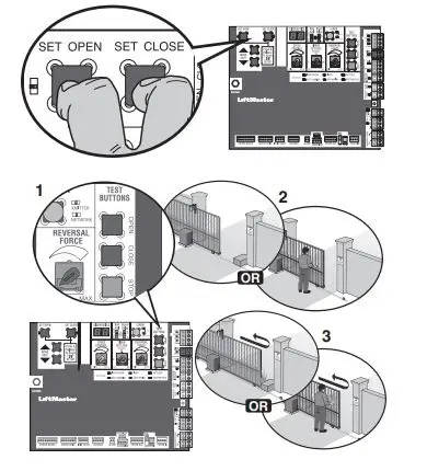
Obstruction Test
The operator is equipped with an inherent (built in to the operator) obstruction sensing device. If the gate encounters an obstruction during motion, the operator will reverse direction of the gate and then stop. The following procedure will test ONLY the inherent (built in to the operator) obstruction sensing device:
- Open and close the gate with the TEST BUTTONS, ensuring that the gate is stopping at the proper open and close limit positions.
- Either place an object between the open gate and the fixed closed catch post or obstruct the gate by hand. Make sure that any external entrapment protection devices, such as an edge or photoelectric sensor will NOT be activated by the object or by hand.
- Run the gate in the close direction. The gate should stop and reverse upon contact with the object or hand. If the gate does not reverse, reduce the force setting by turning the force control slightly counter-clockwise. The gate should have enough force to reach both the open and close limits, but MUST reverse after contact with an object or hand.
- Repeat the test for the open direction.
PROGRAMMING
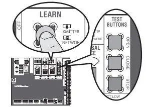
Remote Controls (Not Provided)
A total of 50 Security+ 2.0® remote controls or KPW250 keypads and 2 keyless entries (1 PIN for each keyless entry) can be programmed to the operator. When programming a third keyless entry to the operator, the first keyless entry will be erased to allow the third keyless entry to be programmed. When the operator’s memory is full it will exit the programming mode and the remote control will not be programmed. The memory will need to be erased before programming any additional remote controls. NOTE: If installing an 86LM to extend the range of the remote controls DO NOT straighten the antenna.
There are 3 different options for programming the remote control depending on how you would like the remote control to function. Choose a programming option:
The operator will automatically exit learn mode (operator will beep and green XMITTER LED will go out) if programming is successful. To program additional Security+ 2.0® remote controls or remote control buttons, repeat the programming steps above.
| OPTION | DESCRIPTION | PROGRAMMING STEPS |
| Single button as OPEN only | Program a single button on the remote control for open only. The Timer-to-Close can be set to close the gate. | 1. Press and release the LEARN button (operator will beep and green XMITTER LED will light). NOTE: The operator will time out of programming mode after 30 seconds.
2. Press the OPEN button. 3. Press the remote control button that you would like to program. |
| Single button (SBC) as OPEN, CLOSE, and STOP | Program one remote control button as an open, close, and stop. | 1. Press and release the LEARN button (operator will beep and green XMITTER LED will light). NOTE: The operator will time out of programming mode after 30 seconds.
2. Press the remote control button that you would like to program. |
| Three separate buttons as OPEN, CLOSE, and STOP | Program each remote control button as an open, close, and stop. | 1. Press and release the LEARN button (operator will beep and green XMITTER LED will light). NOTE: The operator will time out of programming mode after 30 seconds.
2. Press the OPEN, CLOSE, or STOP button, depending on the desired function. 3. Press the remote control button that you would like to program. |
Entering programming mode using external reset button or 3-button control station:
- Make sure gate/door is closed.
- Give the operator an OPEN command.
- To put the operator into high band programming mode, give the operator an OPEN command. Within 30 seconds, when the gate is at the open limit, press the reset button three times or push the button on the control station three times. NOTE: The operator will time out of programming mode after 30 seconds.
Fcc Rules
NOTICE: This device complies with Part 15 of the FCC rules and Industry Canada’s license-exempt RSSs. Operation is subject to the following two conditions:
- this device may not cause harmful interference,
- this device must accept any interference received, including interference that may cause undesired operation.
Any changes or modifications not expressly approved by the party responsible for compliance could void the user’s authority to operate the equipment. This device must be installed to ensure a minimum 20 cm (8 in.) distance is maintained between users/bystanders and device. This device has been tested and found to comply with the limits for a Class B digital device, pursuant to part 15 of the FCC rules and Industry Canada ICES standard. These limits are designed to provide reasonable protection against harmful interference in a residential installation. This equipment generates, uses and can radiate radio frequency energy and, if not installed and used in accordance with the instructions, may cause harmful interference to radio communications. However, there is no guarantee that interference will not occur in a particular installation. If this equipment does cause harmful interference to radio or television reception, which can be determined by turning the equipment off and on, the user is encouraged to try to correct the interference by one or more of the following measures:
- Reorient or relocate the receiving antenna.
- Increase the separation between the equipment and receiver.
- Connect the equipment into an outlet on a circuit different from that to which the receiver is connected.
- Consult the dealer or an experienced radio/TV technician for help.
![]()
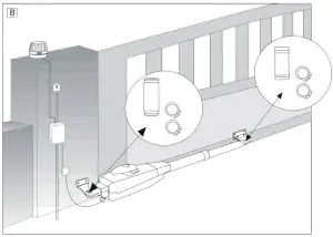
LA400EV
Automatic Gate Opener*
*For GB (UK, NI) specific information on national regulations and requirements see English part of the manual.
NOTE: The original installation and operating instructions were compiled in Germany. Any other available language is a translation of the original Germany version.
General Safety Guidelines
![]() This safety alert symbol means „Caution“ – failure to comply with such instruction involves risk of personal injury or damage to property.Please read these warnings carefully.
This safety alert symbol means „Caution“ – failure to comply with such instruction involves risk of personal injury or damage to property.Please read these warnings carefully.
![]() This gate drive mechanism is designed and tested to offer appropriately safe service provided it is installed and operated in strict accordance with the following safety rules. Incorrect installation and/or failure to comply with the following instructions may result in serious personal injury or property damage.
This gate drive mechanism is designed and tested to offer appropriately safe service provided it is installed and operated in strict accordance with the following safety rules. Incorrect installation and/or failure to comply with the following instructions may result in serious personal injury or property damage.
![]() When using tools and small parts to install or carry out repair work on a gate exercise caution and do not wear rings, watches, or loose clothing.
When using tools and small parts to install or carry out repair work on a gate exercise caution and do not wear rings, watches, or loose clothing.
![]() Installation and wiring must be in compliance with your local building and electrical installation codes. Power cables must only be connected to a properly earthed supply.
Installation and wiring must be in compliance with your local building and electrical installation codes. Power cables must only be connected to a properly earthed supply.
![]() Any entrapment possibility by the moving wing between wing & walls must be secured with safety edges or IR sensors.
Any entrapment possibility by the moving wing between wing & walls must be secured with safety edges or IR sensors.
![]() Please remove any locks fitted to the gate in order to prevent damage to the gate.
Please remove any locks fitted to the gate in order to prevent damage to the gate.
![]() After the installation, a final test of the full function of the system and the full function of the safety devices must be done.
After the installation, a final test of the full function of the system and the full function of the safety devices must be done.
![]() This drive cannot be used with a gate incorporating a wicket door unless the drive cannot be operated with the wicket door open.
This drive cannot be used with a gate incorporating a wicket door unless the drive cannot be operated with the wicket door open.
![]() It is important to make sure that the gate always runs smoothly. Gates that stick or jam must be repaired immediately. Employ a qualified technician to repair the gate, never attempt to repair it yourself.
It is important to make sure that the gate always runs smoothly. Gates that stick or jam must be repaired immediately. Employ a qualified technician to repair the gate, never attempt to repair it yourself.
![]() Keep additional accessories away from children. Do not allow children to play with pushbuttons or remote controls. A gate can cause serious injuries as it closes.
Keep additional accessories away from children. Do not allow children to play with pushbuttons or remote controls. A gate can cause serious injuries as it closes.
![]() Disconnect electric power to the system before making repairs or removing covers. A disconnecting device must be provided in the permanently-wired installation to guarantee all-pole disconnection by means of a switch (at least 3mm contact gap) or by a separate fuse.
Disconnect electric power to the system before making repairs or removing covers. A disconnecting device must be provided in the permanently-wired installation to guarantee all-pole disconnection by means of a switch (at least 3mm contact gap) or by a separate fuse.
![]() Make sure that people who install, maintain or operate the gate drive follow these instructions. Keep these instructions in a safe place so that you can refer to them quickly when you need to.
Make sure that people who install, maintain or operate the gate drive follow these instructions. Keep these instructions in a safe place so that you can refer to them quickly when you need to.
![]() The full protection against potential squeeze or entrapment must work directly when the drive arms are installed.
The full protection against potential squeeze or entrapment must work directly when the drive arms are installed.
Content
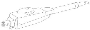
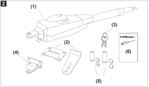
- Motor LA400EV (1x)
- Postbracket (1x)
- Key (2x)
- Gate fixing bracket (1x)
- Clevis pin (2x) and rings (4x)
- Manual (1x)
BEFORE YOU BEGIN
The drive mechanism needs room to the side permitting correct installation of drive arms. Please make sure that this is available. Gates affected by high wind loads must also be protected by an (electric) lock.
There are many factors to consider when choosing the right drive mechanism. Assuming that a gate functions properly, „startup“ is the most difficult phase, once the gate
is in motion, significantly less force is usually required to move it.
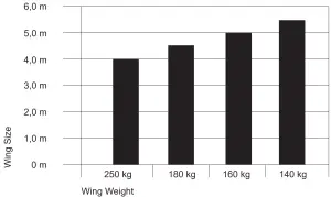
- Gate size: Gate size is a very important factor. Wind can break or distort the gate, thereby increasing the amount of force needed to move it considerably.
- Gate weight: The weight of the gate in not as relevant as the size.
- Effect of temperature: Low outdoor temperatures can make initial startup more difficult (changes in the ground, etc.) or even prevent it.
- Duty cycle: 24-volt drives can run permanently.
INSTALLATION CHECKLIST – PREPARATIONS
Check the carton contents and read the instructions carefully. Make sure your gate equipment operates perfectly. The gate must run evenly and smoothly and must not stick at any point. Remember that the ground level may be several centimeters higher in winter. The gate must be stable and as free of backlash as possible in order to prevent any unwanted to and fro movement. The more smoothly the gate leaf runs, the more sensitive the force adjustment must be.
Note down any materials you still need and obtain them before starting to install. Heavy-duty plugs, bolts, gate stops, cables, distribution boxes, tools, etc.
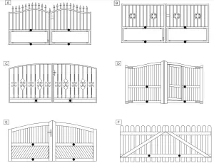
Gate Types
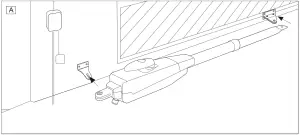
The gate type determines the location where the drive mechanism is installed. If the gate stop is on the ground, the drive mechanism must also be installed at a height that is as low as possible so that it cannot twist the gate. Use only parts of the gate frame for fixing purposes.
TYPE A, B, C
For steel gates, the gate fitting must be attached to the mainframe. If you are uncertain whether the available support is sufficiently stable, reinforce it.
TYPE D, E, F
In the case of wooden gates, the gate fitting must be through-bolted. It is advisable to fit a plate from the outside so that the fixing brackets cannot become loose over time. Thin wooden gates must also be reinforced in order to withstand the stresses encountered (e.g. type F).
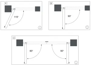
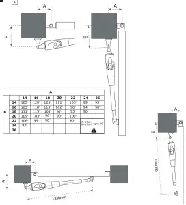
Gate Configuration
How far must the gate leaf open?
90 degrees or up to 115 degrees. An opening angle in excess of 115 degrees is possible to a limited extent but is not recommended. Reason: the drive mechanism always
runs at the same speed. The further the gate has to be opened, the faster the gate leaf must travel. Movement becomes more erratic and this subjects the fittings and gate to
extreme stresses.
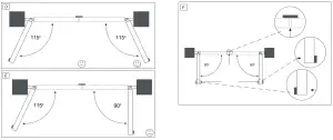
For gates without limit switches: Non-identical opening angles cause one drive mechanism to reach its destination first, but continue to run, thereby forcing the gate up against the gate stop until the other motor eventually reaches its end position (see figure 4A-F).
Tip for professionals: The time taken to reach the limit stop can be controlled by deliberately selecting different A and B dimensions (left + right). However, this method of installing subjects the fittings to high stresses and can cause the gate to run erratically. It is recommended that only experienced gate installers adopt this method.
NOTE: If the gate opens towards a wall, there is a risk of entrapment. Should the distance between the wall and the open gate be less than 200 mm, this area must later be secured via a light barrier or contact strip.
Gate Stops
It is advised to use a fixed gate stop in both the open and close directions. Gate stops save wear and tear on the drive mechanism, gate, and fittings. Operating a gate without fixed limit stops results in poor performance. It is often dangerous, leads to premature wear, and voids your warranty!
Post Fixing Bracket
Choosing the correct location for the post-fixing bracket has a decisive impact on the subsequent functioning of the system. It determines the distance between the motor‘s entre of motion and the gate‘s center of motion and hence the opening angle. These dimensions are referred to as dimension A and dimension B. Do not underestimate the effect that these dimensions have on correct functioning and running. Try and achieve the best dimension for your opening angle, as precisely as possible and suitable for all
circumstances.See Table (figure 5A) for dimensionsA/B.
If the post is not wide enough, an extension piece must be fitted to it (figure 6B). If the post is too thick, cut out part of it to make it thinner (figure 6D)or offset the gate (figure 6C).
To obtain ideal dimensions, it may be necessary to shorten or lengthen the supplied hinge plate. In the case of gates that are to be custom made, if the gate hinges are fitted on the posts appropriately, it is possible to influence dimensions A and B. Before the final mounting dimensions are determined, you should always check whether or not there is any possibility that the corner of the drive mechanism will hit the post as the gate swings.
INSTALLATION: The drive mechanism exerts a considerable force against the post. Usually, acceptable mounting dimensions are obtained if the supplied hinge plate is welded directly onto the post. In the case of thick stone or concrete posts, the hinge must be welded to a base plate and attached so that the plugs cannot work loose during operation. Heavy-duty plugs where a threaded rod is bonded into the masonry stress-free are more suitable for this purpose than steel or plastic straddling plugs. In the case of brickwork pillars, bolt on a relatively large steel plate that covers several bricks and then welds the hinge plate to it. An angle plate attached over the corner of the post is also a good means of fixing the operators.
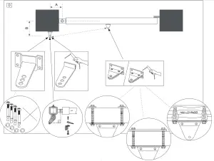
Gate Fitting
The gate fitting must be installed so that it is horizontal relative to the post bracket. The distance between the gate bracket and post bracket is referred to as the „arm span“. When the gate is closed, the drive mechanism is 99% extended. When the gate is opened, the drive mechanism is 1% extended. Fully retracting or extending the lunger/spindle in operation (with gate) damages the drive mechanism and voids the warranty. It is absolutely imperative to comply with the required arm span under all circumstances! For steel gates, fixings should be welded on or through-bolted. When bolting the gate, use large washers or a plate on the other side. The drive mechanism exerts an extremely high force on this joint. Fixings must be through-bolted for wooden gates. Wood deflects under load and the bolt will become loose. Due to movement caused by repeated loading, the wood deflects more and more until the gate no longer closes correctly and has to be repaired. Fit a reinforcing plate from the outside and one on the inside so that the wood cannot deflect and the joint cannot become loose. Thin wooden gates without a metal frame must also be reinforced in order to withstand continuous stresses (e.g. type F).
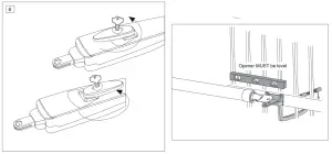
Release
The drive mechanism can be released. The gate can then be opened and operated manually (power failure). With a new drive mechanism, the release action may sometimes feel stiff/jerky. This is normal and has no effect on function.
Release: Insert the key in the cylinder lock and turn it 180 degrees. Then turn the release lever 180 degrees – done!
Engage: Turn the lever glockwise. As soon as the gate moves or the drive runs, the gear locks again. Use the lock to protect the liver against unauthorized release.
Installing The Drive Arm
Release the drive. Push the released drive onto the fittings and secure it by using the supplied bolts, nuts, and rings. „If the center or inner hole, on the hinge plate, is used to fix the post fixing bracket you MUST cut away the remaining section of the hinge plate before activating the arms. Failure to do so will result in breaking the fixing bracket“. Do not use a hammer when you mount the operator on the bracket.
Wiring
The connecting cable has 6 wires, is approx. 3 m long and is run in a curve to the control unit or to a watertight distribution box located above ground. A permanent connection is formed from the distributor box via an appropriate cable.
Connection: See control unit instructions.
Cable colors: Brown/Green/White/Yellow=sensors
Blue/Red: 24-volt motor.
ACCESSORY TIP: Extension cable LA400-JB40
Contains:
(1) 12m cable with terminals
(1) Distribution box IP65
(2) Strain relief PG 13,5
(1) Mounting material
Initial Operation
Check functionality in a disengaged state with the hand on the gate. Initial electrical operation is only possible with a suitable control unit that can be purchased as accessory. Ensure at all times that mechanical and electrical safety instructions applying to the given installation are complied with.
Should the force of the moving wing at its closing edge be higher than 400N, then additional safety facilities (light barrier, contact strip) must be used. Any safety facilities must comply with the requirements set out in EN60335-2-103
Maintenance Work
The drive mechanism is maintenance-free. Check that the gate fittings and the drive mechanism are securely fixed at regular intervals (monthly). Release the drive and check that the gate functions properly. Unless the gate runs smoothly it will not operate correctly with the drive mechanism. The drive cannot eliminate the problems caused by a gate that does not work satisfactorily.
NOTE: also see owners manual of Electronic Control
Disposal
 Our electrical and electronic equipment may not be disposed of with household waste and must be disposed of after use properly in accordance with WEEE Directive EU: 2012/19/ EU; GB UK(NI): SI 2012 nr.9 on waste electrical and electronic equipment in order to ensure that materials are recycled. Collecting waste electrical equipment separately means environmentally-friendly disposal and is completely free of charge for the consumer.WEEE Reg. no. in Germany: DE66256568. Any waste packaging leftover with the end consumer must be collected separately from mixed waste, in accordance with the Directive. Packaging may not be disposed of with household waste, organic waste, or in nature. Packaging material must be separated according to its material and disposed of in the recycling containers provided and in certain council recycling bins.
Technical Data
| Motor Voltage | 24 Volt |
| Current consumption | 2:00 AM |
| Power consumption | 48 W |
| Max. gate width | 4,0 m |
| Max. gate weight | 250 kg |
| Protection Class | I – IP44 |
| Force (nominal) | 250 N |
| Travel Speed | variable |
| Opening time 90° | 14 sec. |
| Temperature | -20°C to + 55°C |

http://www.liftmaster.eu
Chamberlain GmbH
Saar-Lor-Lux-Str. 19
66115 Saarbrücken
Germany
WEEE-Reg.Nr. DE66256568
www.liftmaster.eu
[email protected]![]()
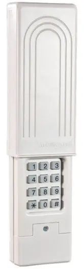
LiftMaster 387LM Universal Wireless Keyless Entry Garage Door Keypad
Read instructions thoroughly BEFORE beginning. Start with the garage door closed. Determine garage door opener type-Smart/Learn button or DIP Switch. The Smart/Learn button or DIP Switches are located on the motor unit or external receiver. Refer to the owner’s manual if necessary. LiftMaster products are intended to be used only with garage door openers manufactured after 1993 that utilize photo-eyes safety sensors. These are always located on or near the bottom of the door track. If your garage door does not have the sensors attached and working, the opener is not compliant with current federal safety regulations and should be replaced.
WARNING
To prevent possible SERIOUS INJURY or DEATH from a moving gate or garage door:
- ALWAYS keep remote controls out of reach of children. NEVER permit children to operate, or play with remote controls.
- Activate gate or door ONLY when it can be seen clearly, is properly adjusted and there are no obstructions to door travel.
- ALWAYS keep the gate or garage door in sight until completely closed. NEVER permit anyone to cross the path of a moving gate or door.
- This product can expose you to chemicals including lead, which is known to the State of California to cause cancer or birth defects, or other reproductive harm. For more information go to www.P65Warnings.ca.gov
Determine Garage Door Opener Types:
Proceed with instructions according to your garage door opener type. NOTE: Your motor unit and/or remote control may look different.
TYPE 1
Chamberlain, Sears Craftsman, LiftMaster, Master Mechanic and Do It garage door openers or receivers with 3 position DIP switches. 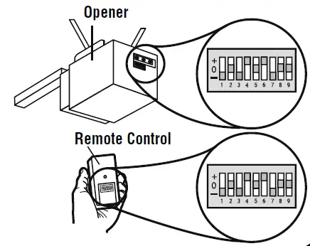
TYPE 2
Genie, Linear, and Moore-O-Matic garage door openers or receivers with 2 position DIP switches.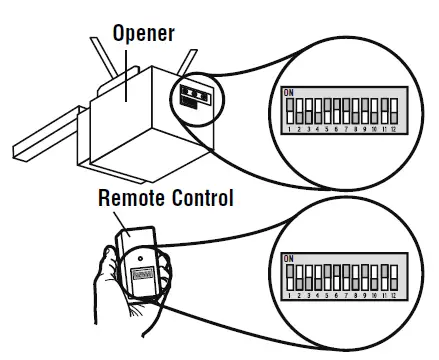
TYPE 3
Chamberlain, Sears Craftsman, LiftMaster, Master Mechanic and Do It garage door openers or receivers with Yellow, white or grey Smart/Learn buttons.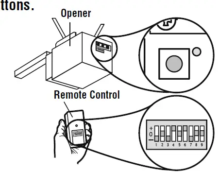
TYPE 4
Chamberlain, Sears Craftsman, LiftMaster, Master Mechanic, Do It, Genie Intellicode, Overhead Door, Stanley, Wayne Dalton or Linear garage door openers with
Smart/Learn button 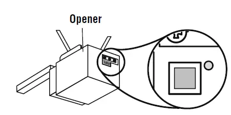
Programming
TYPE 1
- Select and write a 4-digit PIN
- Determine your opener ID using the list below. ID DIP Switch Type
- 11 = 9 DI P switch garage door openers (U.S.)
- 12 = 9 DIP switch garage door openers (Canada)
- 15 = 8 DIP switch garage door openers
- 19 = 7 DIP switch garage door openers (Write opener ID here: __ __)
- 3. The first DIP switch must be set to the “-” position on your remote and opener. Record your DIP switch sequence for the remaining DIP switches. If the
DIP switch is in the “+” position place a 1, “0” position place a 2, “-” position place a 3 in the corresponding box in the chart below:
NOTE: Leave any unused switch locations blank.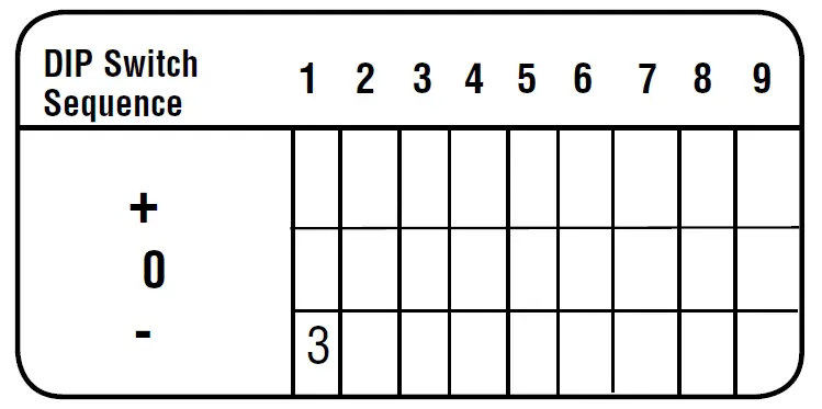 Write your DIP switch sequence below:
- Press and # keys together until the keypad stops flashing.
- Enter the PIN from step 1, and press #.
- Enter the ID from step 2, and press #.
- Enter the DIP switch sequence from step 3 and press the # key.
- To test and use, wait until the lights turn off, enter your PIN and press the 0 key. If the opener does not function, repeat programming.
TYPE 2
- Select and write a 4-digit PIN:
- Determine your opener ID using the list below. ID DIP Switch Type
- 13 = 12 DIP switch Genie garage door openers
- 14 = 10 DIP switch Linear garage door openers
- 16 = 10 DIP switch Stanley garage door openers
- 17 = 9 DIP switch Genie garage door openers
- 18 = 8 DIP switch Linear, Moore-O-Matic garage door openers (Write opener ID here: __ __)
- Record your DIP switch sequence. If the DIP switch is in the “on” or “up” position place a 1, “off” or “down” position place a 2 in the corresponding box in the chart below:
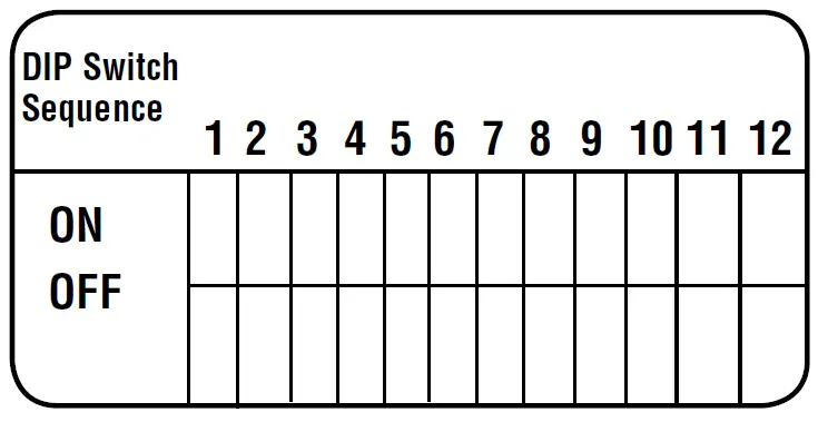
NOTE: Leave any unused switch locations blank.
Write your DIP switch sequence below:
- Press * and # keys together until the keypad stops flashing.
- Enter the PIN from step 1, press #
- Enter the ID from step 2, and press #.
- Enter the DIP switch sequence from step 3 and press the # key.
- To test and use, wait until the lights turn off, enter your PIN and press the 0 key.
- If the opener does not function, flip DIP switches, so if a switch is “on” or “up” flip it “off” or “down” in step 3.
TYPE 3
- Select and write a 4-digit PIN:
- 2. Your opener ID is 11.
- Record your DIP switch sequence. Set your first DIP switch to “-”, your first DIP switch must be set to the “-” position on your remote and opener. If the DIP switch is in the “+” position place a 1, “0” position place a 2, “-” position place a 3 in the corresponding box in the chart below:
NOTE: Leave any unused switch locations blank.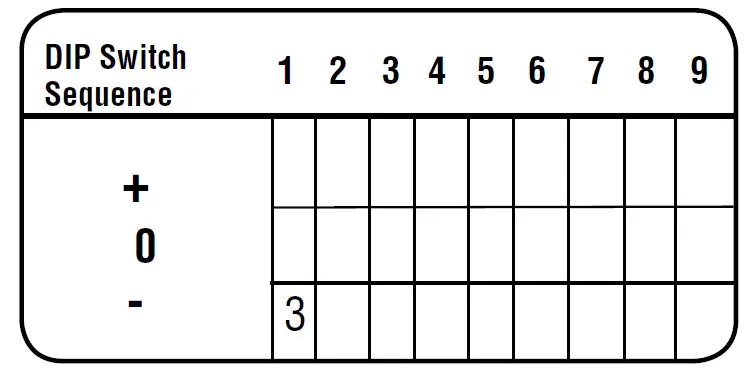
Write your DIP switch sequence below:
- Press * and # keys together until the keypad stops flashing.
- Enter the PIN from step 1, and press #.
- Enter 11, press #.
- Enter the DIP switch sequence from step 3press #.
- Press and release the Smart/Learn button on the garage door opener.
- Enter your 4-digit PIN and press the 0 key.
- To test and use, wait until the light turns off, enter your PIN and press the 0 key. If the opener does not function, repeat programming.
TYPE 4
- Select and write a 4-digit PIN:
- Determine your opener ID using the list below.ID Garage door opener brand and manufacturing dates
- 1 = Linear garage door openers manufactured from 1997 to the present.
- 2 = Chamberlain, Sears Craftsman LiftMaster, Master Mechanic, and Do It garage door openers manufactured from 1997 to 2004 [Orange Button].
- 3 = Chamberlain, Sears Craftsman, LiftMaster, Master Mechanic, and Do It garage door openers manufactured from 2005 to the present [Purple Button].
- 4 = Chamberlain, Sears Craftsman, LiftMaster, Master Mechanic, and Do It garage door openers manufactured from 1993 to 1996 [Green Button].
- 5 = Genie Intellicode and Overhead Door garage door openers manufactured from 2005 to the present (315 MHz).
- 6 = Genie Intellicode and Overhead Door garage door openers manufactured from 1995 to the present (390 MHz).
- 7 = Stanley garage door openers manufactured in 1998-present.
- 8 = Chamberlain, Sears Craftsman, LiftMaster, Master Mechanic, and Do It garage door openers manufactured from 2011 to the present [Yellow Button].
- 9 = Wayne Dalton garage door openers manufactured in 1999-present (372.5 MHz).
Write opener ID here:
- Press * and # keys together until the keypad stops flashing.
- Enter the PIN from step 1, press #.
- Enter the ID from step 2, and press #.
- Press and release the Smart/Learn button on the garage door opener.
- Enter your 4-digit PIN and press the 0 key. NOTE: Genie and Overhead Door units, press “0” twice.
- o test and use, wait until the light turns off, enter your PIN, and press the 0 key. If the opener does not function, repeat programming.
MOUNT THE KEYPAD
Install out of the reach of children at a minimum height of 5 feet (1.5 m). Secure the keypad to a smooth surface. Mount the keypad out of the path of the moving garage door, but within sight of it (4″(10 cm) clearance is needed for the cover.)
- Remove cover.
- Remove battery cover to expose mounting holes.
- Remove battery and mount keypad using screws provided.
- Reassemble.
CHANGING YOUR 4-DIGIT PIN
- Enter the existing PIN, press enter a new PIN, and press. To test and use, enter your new PIN and press the 0 key
- .LiftMaster.com 1-800-442-1255 LiftMaster is a Trademark of LiftMaster. Chamberlain and Moore-O-Matic are Trademarks of Chamberlain Group.
- Genie and Intellicode are Trademarks of GMI Holdings, Inc.Overhead Door is a Trademark of Overhead Door Corporation. Linear is a Trademark of Linear Corporation.
- Master Mechanic is a Trademark of TruServ. Sears is a Trademark of Sears & Roebuck. Stanley is a Trademark of The Stanley Works.
- Wayne Dalton is a Trademark of Wayne Dalton Corporation. Do It is a Trademark of Do It Best Corporation.
BATTERY
Warning
- To prevent possible SERIOUS INJURY or DEATH
- NEVER allow small children near batteries.
- If the battery is swallowed, immediately notify the doctor. Replace the 9-Volt battery when the keypad light becomes dim or does not light up.
- Slide cover-up, remove the battery cover, and replace the battery. Re-programming may be necessary.
NOTICE
To comply with FCC and or Industry Canada (IC) rules, adjustments or modifications of this receiver and/or transmitter are prohibited, except for changing the code setting or replacing the battery. THERE ARE NO OTHER USER-SERVICEABLE PARTS.
- Tested to Comply with FCC Standards FOR HOME OR OFFICE USE. Operation is subject to the following two conditions:
- This device may not cause harmful interference,
- This device must accept any interference received, including interference that may cause undesired operation.
- This device must be installed to ensure a minimum 20 cm (8 in.) distance is maintained between users/bystanders and the device.
LiftMaster 891LM Remote Controls Instruction Manual
For use with Security+ 2.0® products. All Security+ 2.0® Garage Door Openers have a yellow Learn button and two yellow antennas. The code between the remote control and the receiver changes with each use, randomly accessing over a billion new codes. Refer to your product manual for the location of the learn button.
NOTE: Your product may look different than the products illustrated in this manual.
Single Button Remote Control Model 891LM
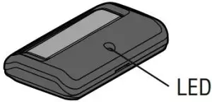
3-Button Remote Control Model 893LM
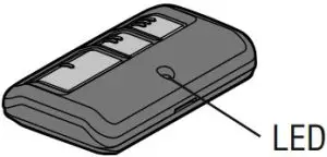
Warning
To prevent possible SERIOUS INJURY or DEATH from a moving gate or garage door:
- ALWAYS keep remote controls out of reach of children. NEVER permit children to operate, or play with remote controls.
- Activate gate or door ONLY when it can be seen clearly, is properly adjusted, and there are no obstructions to door travel.
- ALWAYS keep gate or garage door in sight until completely closed. NEVER permit anyone to cross path of moving gate or door.
WARNING: This product can expose you to chemicals including lead, which are known to the State of California to cause cancer or birth defects or other reproductive harm. For more information go to www.P65Warnings.ca.gov.
PROGRAM USING THE GARAGE DOOR OPENER
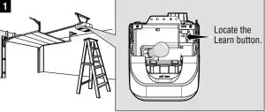
- Press and immediately release the Learn button. The Learn LED will glow steadily for 30 seconds. Within 30 seconds…
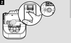
- Press and hold the button on the remote control that you wish to use.
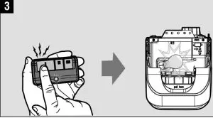
Release the button when the garage door opener lights blink or two clicks are heard. If programming to other products, press the button a second time to activate the product.
PROGRAM USING THE DOOR CONTROL
- Press the LEARN button on the door control to enter Programming Mode.
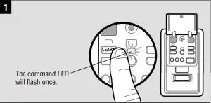
The command LED will flash once. - Press the LEARN button again, the LED will flash once.
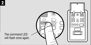
The command LED will flash once again. - Press and hold the button on the remote control that you wish to use.
Release the button when the garage door opener lights blink or two clicks are heard. If programming to other products, press the button a second time to activate the product.
TO ERASE ALL CODES FROM MEMORY
When deactivating any unwanted remote control code, all previous codes will be erased.
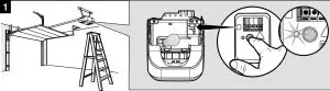
Press and hold the Learn button on garage door opener or other product until the learn LED goes out (approximately 6 seconds). All previous codes are now erased. Reprogram each remote control you wish to use.
TO CONTROL THE GARAGE DOOR OPENER LIGHTS
This feature is only available on garage door openers equipped with a multi-function door control and a remote control with more than one button. Not available with external receiver. A remote control button can be programmed to operate the garage door opener lights without opening the door.
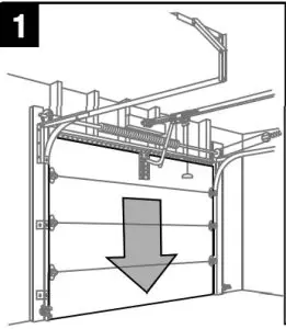
With the door closed, press and hold the remote control button that you want to control the light.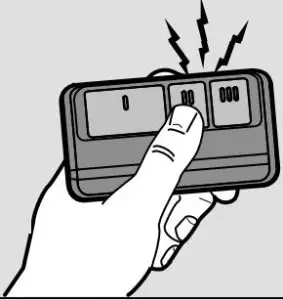
- Press and hold the + LIGHT button on the door control.
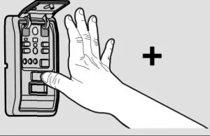
- Press and hold the + LOCK button on the door control.
After the garage door opener lights flash, release all buttons.
Test by pressing the remote control button. The garage door opener lights should turn on or off but the door should not move.
THE REMOTE CONTROL BATTERY
The Lithium battery should produce power for up to 3 years. If the battery is low, the remote control’s LED will not flash when the button is pressed. To replace battery:
- Pry open the case first in the middle (1), then at each side (2 and 3) with the visor clip.
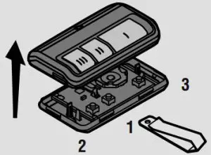
- Remove the old battery. Dispose of old batteries properly.
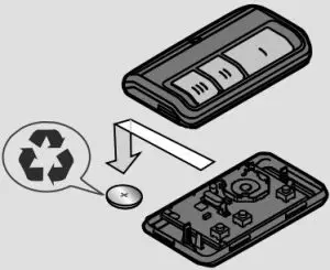
- Insert replacement batteries positive side up. Replace the batteries with only 3V CR2032 coin cell batteries.
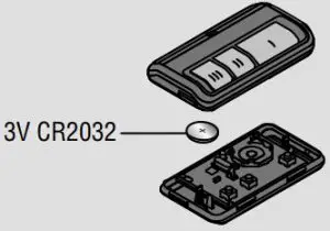
- Replace cover.
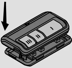
Warning
To prevent possible SERIOUS INJURY or DEATH:
- NEVER allow small children near batteries.
- If battery is swallowed, immediately notify doctor.
To reduce risk of fire, explosion or chemical burn:
- Replace ONLY with 3V CR2032 coin batteries.
DO NOT recharge, disassemble, heat above 212° F (100° C) or incinerate.
LiftMaster 891LM Remote Controls Instruction Manual
Make: LiftMaster
Model: 891LM, 893LM
Description: Remote Control Uses 1 3Vdc battery (CR2032) Country of Origin: Mexico
3V CR2032 Remote Control 893LM: IFT #: RCPLI8917-2064 Remote Control 891LM: IFT #: RCPLI8918-0755 Operation of this equipment is subject to the following two conditions: (1) This equipment or device may not cause harmful interference and (2) this equipment or device must accept any interference, including that which may cause undesired operation.
NOTICE: To comply with FCC and or Industry Canada rules (IC), adjustment or modifications of this receiver and/or transmitter are prohibited, except for changing the code setting or replacing the battery. THERE ARE NO OTHER USER SERVICEABLE PARTS. Tested to Comply with FCC Standards FOR HOME OR OFFICE USE. Operation is subject to the following two conditions: (1) this device may not cause harmful interference, and (2) this device must accept any interference received, including interference that may cause undesired operation.
HOW TO USE THE REMOTE CONTROL
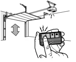
Press and hold the button down until the door or gate starts to move. The remote control will operate from up to 3 car lengths away on typical installations. Installations and conditions vary, contact an installing dealer for more information.
3-BUTTON REMOTE CONTROLS
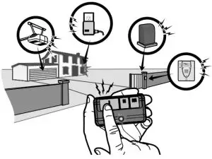
Additional buttons on the remote control can be programmed to operate up to 3 devices such as additional garage door openers, light controls, gate operators or access control systems.
REPLACEMENT PARTS
3V CR2032 Lithium battery: 10A20
Visor Clip: 29B137
ONE YEAR LIMITED WARRANTY
LiftMaster warrants to the first consumer purchaser of this product that it is free from defect in materials and/or workmanship for a period of 1 year from the date of purchase.
114A3936F
]]>LiftMaster 893MAX Universal Gate and Garage Door Opener Remote
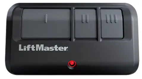
893MAX Remote Manual
Step 1: Confirm Color of Button
Check what color is the learn button behind the garage door opener
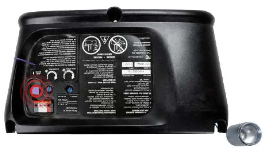
Step 2:Programming Initiation
Press and Hold the III and II button at the same time till the led indicator flash 4 times and then release it
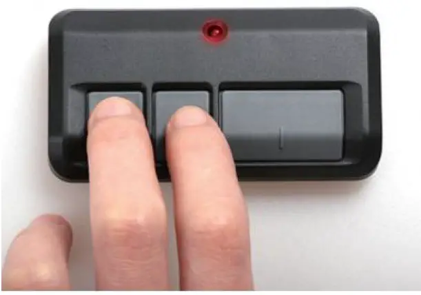
Step 3: Choose Code Type
Within 8 seconds, Press and Release the remote control button(one of the 3 buttons) you wish to use, times according to the color of your learn button and the following chart
| Press Times | Garage door opener type |
| 1 | Security+2.0 (Yellow Learning Button) |
| 2 | 315MHz Security+ (Purple Learning Button ) |
| 3 | 390MHz Security+ (Red or Orange Learning Button ) |
| 4 | 390MHz Billion Code (Green Learning Button) |
For example: you want to set II button to be 315MHZ Security+ purple learning button , press and release II button 2 times, LED indicator light on and off, then press I or III button 1 time to fixed the II button code
Step 4: Garage Door Opener Learning
Press and immediately release the learn button, then learn LED will glow steadily for 30 seconds. Within 30 seconds…
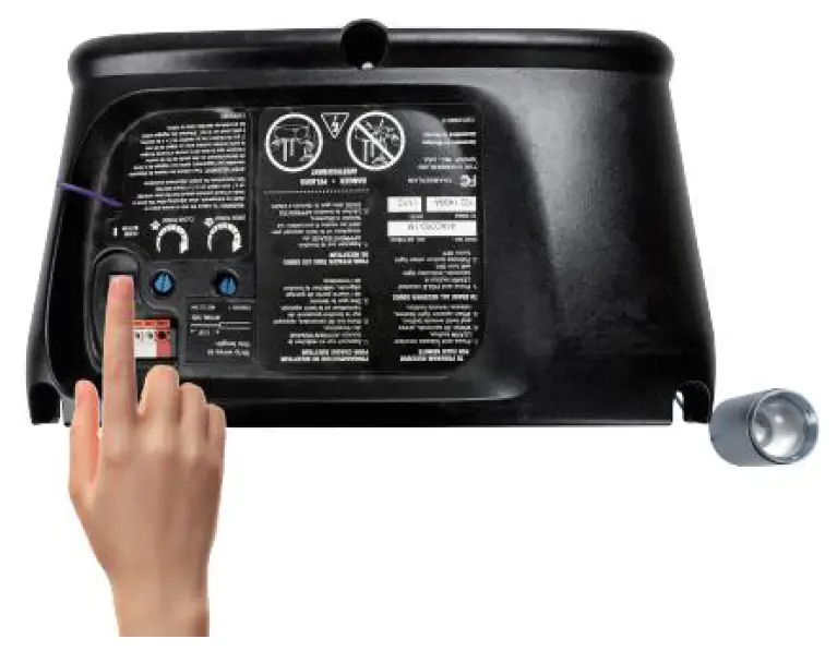
Step 5: Programming Complete
Press and hold the button on the remote control that you wish to use.
Release the button when the garage door openers lights blink or two clicks are heard. If programming to other products, press the button a second time to activate the product.
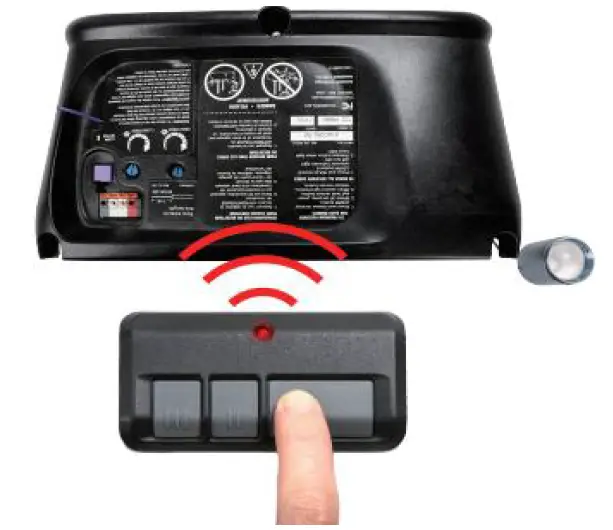
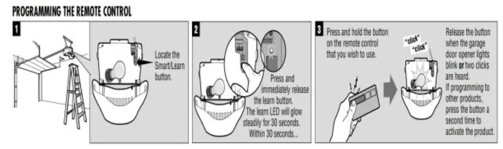
FCC Statement
This device complies with part 15 of the FCC rules. Operation is subject to the following two conditions: (1) this device may not cause harmful interference, and (2)
this device must accept any interference received, including interference that may cause undesired operation.
Changes or modifications not expressly approved by the party responsible for compliance could void the user’s authority to operate the equipment.
NOTE: This equipment has been tested and found to comply with the limits for a Class B digital device, pursuant to part 15 of the FCC Rules.
These limits are designed to provide reasonable protection against harmful interference in a residential installation. This equipment generates uses and can radiate radio frequency energy and, if not installed and used in accordance with the instructions, may cause harmful interference to radio communications. However, there is no guarantee
that interference will not occur in a particular installation. If this equipment does cause harmful interference to radio or television reception, which can be determined by turning the equipment off and on, the user is encouraged to try to correct the interference by one or more of the following measures:
- Reorient or relocate the receiving antenna.
- Increase the separation between the equipment and receiver.
- Connect the equipment into an outlet on a circuit different from that to which the receiver is connected.
- Consult the dealer or an experienced radio/TV technician for help.
The device has been evaluated to meet general RF exposure requirement. The device can be used in portable exposure condition without restriction.
]]>LiftMaster 375UT Universal Remote Control Instruction Manual

Read instructions thoroughly BEFORE beginning. If using the Universal Remote Control with residential door openers, the Universal Remote Control must be used only with door openers manufactured after 1993 that utilize photoelectric sensors. The photoelectric sensors are always located on or near the bottom of the door track.
The Universal Remote Control can be programmed to activate up to two products, such as a garage door opener, gate operator, or commercial door operator. Each button on the Universal Remote Control works independently of the other and must be programmed separately. The second button on the Universal Remote Control can be programmed to different products without affecting the first button programmed. The images throughout this manual are for reference only and your product may look different.
 WARNING: This product can expose you to chemicals including lead, which are known to the State of California to cause canceror birth defects or other reproductive harm. For more information go to www.P65Warnings.ca.gov
WARNING
To prevent possible SERIOUS INJURY or DEATH from a moving gate or garage door:
- ALWAYS keep remote controls out of reach of children. NEVER permit children to operate, or play with remote control transmitters.
- Activate gate or door ONLY when it can be seen clearly, is properly adjusted and there are no obstructions to door travel.
ALWAYS keep gate or garage door in sight until completely closed. NEVER permit anyone to cross path of moving gate or door.
PROGRAMMING
- Start with your garage door, gate, or commercial door closed.
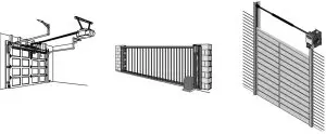
- Open the remote control by sliding the battery cover down. Press and hold the program button until the LED lights (approximately 2 seconds).
- Press and release the SMART/LEARN button on your product.
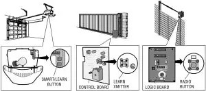
OR
Match the remote control DIP SWITCHES to the existing receiver or existing remote control.
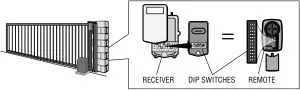
NOTE: The SMART/LEARN button or DIP SWITCHES are located either on the product or in an external receiver on or near the product. Consult your product owner’s manual to locate the SMART/LEARN button or DIP SWITCHES.
NOTE: If you have a 2 position DIP SWITCH and programming fails, reverse DIP SWITCHES (OFF to ON and ON to OFF). - Press and release the button. When the LED stops flashing, continue to press and release the button until a click is heard from the garage door opener, a light on the garage door opener blinks, the garage door opens/closes, or a beep is heard from the gate operator (maximum 18 times).
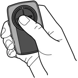
OR
Press and release the Universal Remote Control button…- … 8 times Chamberlain®* Yellow Button 2011-Current
- … 3 times Chamberlain®* Purple Button 2005-Current
- … 2 times Chamberlain®* Orange Button 1997-2005
- … 4 times Chamberlain®*Green Button 1993-1996
- … 6 times Genie Overhead Door® Intellicode 1995-Current
- … 5 times Genie Overhead Door® Intellicode 2005-Current
- … 1 time Linear® Mega-Code 1997-Current
- … 7 times Stanely® Security Code 1998
- … 9 times Wayne Dalton® Rolling Code 372.5 MHz 1999-Current
- … 14 times Linear Multicode® 10 Position Dip Switch
- … 16 times Stanley Multicode® 10 Position Dip Switch
- … 18 times Linear ® 8 Position Dip SwitchThe LED on the Universal Remote Control MUST stop blinking between each press of the button. The code is accepted when a click or beep is heard, a light blinks, or the door/gate activates.
- LiftMaster, Do-It, Master Mechanic, Raynor, True Value and Sears Craftsman are compatible with Chamberlain technology.
- Press the program button to exit programming mode. Programming is now complete.
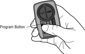
- Press the programmed button to activate your product. If product does not activate, repeat the programming steps 3-6 again.
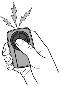
REMOTE CONTROL BATTERY
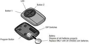
WARNING
To prevent possible SERIOUS INJURY or DEATH:
- NEVER allow small children near batteries.
- If battery is swallowed, immediately notify doctor.
To reduce risk of fire, explosion or chemical burn: - Replace ONLY with 3V CR2032 coin batteries.
- DO NOT recharge, disassemble, heat above 212°F (100°C) or incinerate.
NOTICE: To comply with FCC and or Industry Canada (IC) rules, adjustment or modifications of this receiver and/or transmitter are prohibited, except for changing the code setting or replacing the battery. THERE ARE NO OTHER USER SERVICEABLE PARTS.
Tested to Comply with FCC Standards FOR HOME OR OFFICE USE. Operation is subject to the following two conditions: (1) this device may not cause harmful interference, and (2) this device must accept any interference received, including interference that may cause undesired operation.
CUSTOMER SUPPORT
Website: LiftMaster.com
Phone: 1-800-442-1255
Chamberlain and LiftMaster are Trademarks of Chamberlain Group. Genie is a Trademark of Overhead Door Corporation. Overhead Door is a Trademark of Overhead Door Corporation. Linear is a Trademark of Linear Corporation.
Master Mechanic is a Trademark of TruServ. Sears is a Trademark of Sears & Roebuck. Stanley is a Trademark of The Stanley Works. Wayne Dalton is a trademark of Wayne Dalton Corporation. Do It is a trademark of Do It Best Corporation.
© 2015, Liftmaster
All Rights Reserved

QuickStart for the model T door operator
This QuickStart is intended to highlight a typical installation. These instructions are not intended to be comprehensive. Since each application is unique, it is the responsibility of the purchaser, designer, installer and end user to ensure that the total door system is safe for its intended use. Please consult the manual and/or a qualified technician for further information.
Board Selector Dial Factory Setting is C2*
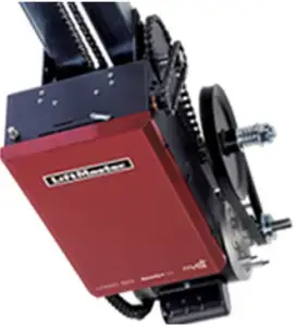
*See installation manual for full description of modes.
Remote Controls
Built in 3-channel, Security 2.0TM radio receiver that allows you to add up to 90 remote control devices and up to 30 keyless entry devices.
CONTROL WIRING 20 AWG or greater
LiftMaster Monitored Entrapment Protection (LMEP) is required for most programmable settings. Thru-Beam Photoelectric Sensors (Shown)
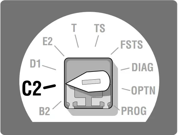
WARNING: This product can expose you to chemicals including lead, which are known to the State of California to cause cancer or birth defects or other reproductive harm. For more information go to www.P65Warnings.ca.gov
MAS Programming (Maintenance Alert System)
- The MAS assists the installing dealer in setting up a routine maintenance program. Once programmed, the MAS notifies the end user (with a flashing LED on the 3 button station) when a preset number of cycles/months has elapsed and scheduled maintenance is due.
- Close the Door.
- Turn the selector dial to Program.
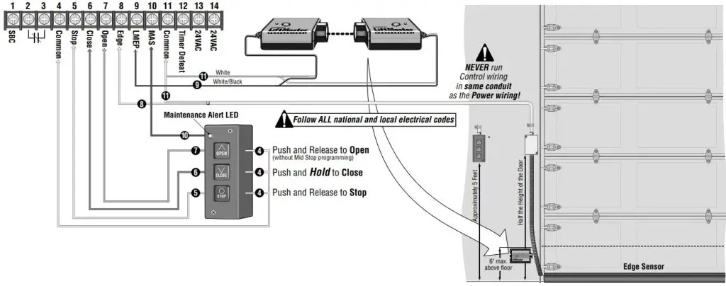
- Press and release the MAS button.
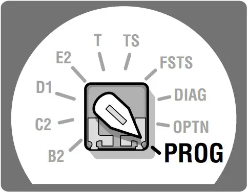
- Press the STOP button once CLOSE D21 to clear the MAS counter.
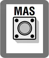
- Press the OPEN button once for every 5,000 Cycles increments. Press the CLOSE button once for every 3 Month increments. Press the STOP button once to Clear the MAS Setting.
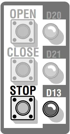
- Press the MAS button to complete the programming. The on board LED will flash back the programmed settings. The OPEN LED will flash once for every 5,000 cycles. The CLOSE LED will flash once for every 3 months.
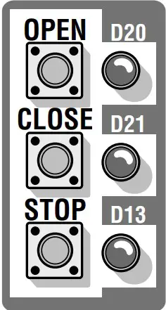
- Turn the selector dial back to the desired wiring type.
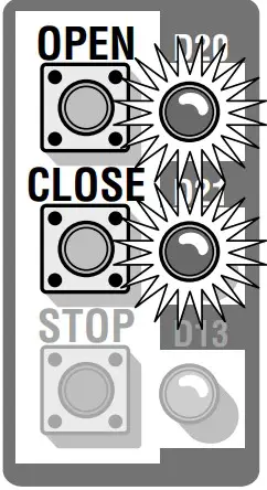
Timer-to-Close Programming
Timer automatically closes door after a preset time.
- Close the Door.
- Turn selector to PROG.
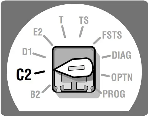
- Press and release the TIMER button.
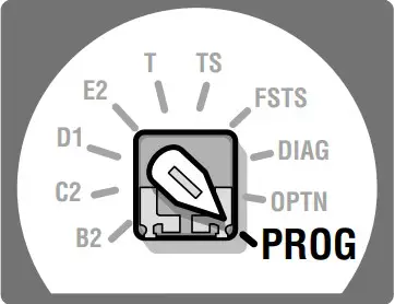
- Press and release the STOP button to clear the timer.
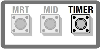
- Press and release the OPEN button once for every 1 second. Press and release the CLOSE button once for every 15 seconds.
Example: Push CLOSE + Push OPEN + Push OPEN = 17 seconds total (15 seconds) (1 second) (1 second)
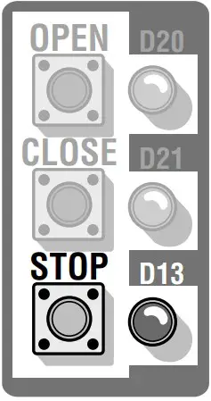
- Press and release the TIMER button to complete programming. MRT
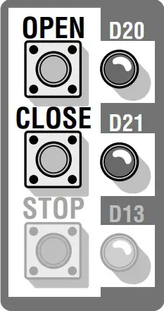 MID TIMER The OPEN LED will flash once for every 1 sec. The CLOSE LED will flash once for every 15 sec.
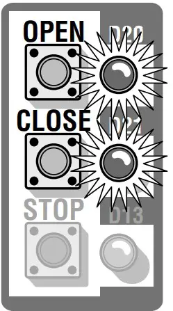
- Turn selector to T, TS or FSTS wiring types.
NOTE: Must have at least one LiftMaster Monitored Entrapment Protection (LMEP) device installed.
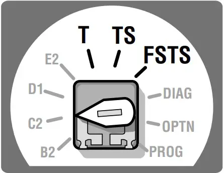
OPEN Mid Stop Programming
The mid stop feature is to open the door to a preset point prior to the fully open position.
- Close the Door.
- Turn selector to PROG.
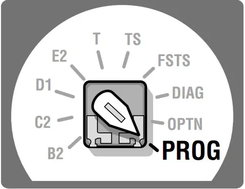
- Press and release the MID button.
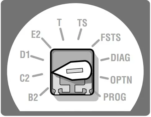
- Press the OPEN button, wait until the door reaches the desired mid stop height, then press and release the STOP button.
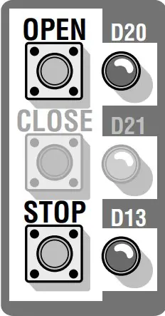
- Press and release the MID button to complete programming.
- Turn selector back to selected wiring type.
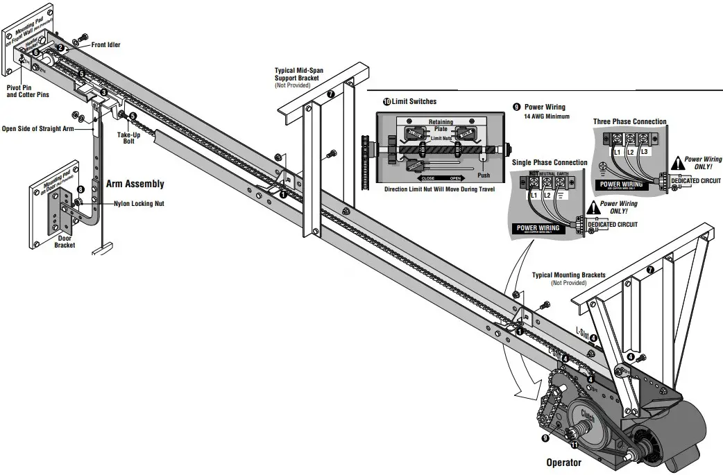
IMPORTANT: This QuickStart is intended to highlight a typical installation. These instructions are not intended to be comprehensive. Since each application is unique, it is the responsibility of the purchaser, designer, installer and end user to ensure that the total door system is safe for its intended use. Please consult the manual and/or a qualified technician for further information.
Inside the Electrical Box

Follow All National and local Electrical codes.
POWER WIRING USE COPPER WIRE ONLY
- Install the track spacers down the track (as shown). The nylon pad on the spacer bracket must face up. (Two -1″ bolts/nuts per spacer)
- Install the front idler in the second hole from the end of the track. (Two -1″ bolts/nuts with lock washers)
- Slide the trolley into the tracks so that the take-up bolt will be facing toward the operator.
- Secure the operator to the tracks using the L-slot and the 3rd hole for each track. (Four -1″ bolts/nuts)
- Connect the chain to the trolley carriage connection on the door end. Connect the take-up bolt on the other end and adjust chain accordingly. A properly adjusted chain will sag about 3 inches at the mid-point. If necessary, remove links from the chain to achieve proper adjustment. (Two nuts and a lock washer, two master links)
- Provide a mounting pad for the header bracket to attach to the front wall. Then use the pivot pin and cotter pins to secure the track assembly to the header bracket (with the operator remaining on the floor).
- Secure some mounting brackets to the operator. Pivot the operator up until track assembly is horizontal with the header bracket then secure the brackets to the ceiling. If the track is longer than 15 feet, use of a mid-span support bracket is recommended.
- Assemble the curved and straight arm as shown making sure the open side of the notch on the straight arm faces the door, (Two -1″ bolts/nuts). Attach arm assembly to the door bracket with a 1″ bolt and nylon locking nut so the bolt can pivot.
- Run the power wires through the power wiring conduit hole in the electrical box enclosure. Connect the power to the operator. Connect the earth ground to the ground screw in the electrical box enclosure. Follow ALL national and local electrical codes.
- Adjust the limit switches to open and close door properly. Make sure the limit nuts are positioned between the limit switches before proceeding with adjustments.
- Remove cotter pin from nut on the clutch shaft. Back off clutch nut until there is very little tension on the clutch spring. Tighten clutch nut gradually until there is just enough tension to permit the operator to move the door smoothly but to allow the clutch to slip if the door is obstructed. When the clutch is properly adjusted, it should generally be possible to stop the door by hand during travel. Reinstall cotter pin when finished.
- Radio programming instructions inside cover of operator.
APPLICATION
The MyQ® Control Panel is intended to be installed with Security+™ Garage Door Openers manufactured between 1998 and present. The MyQ® Control Panel is NOT compatible with Security+ 2.0™ Garage Door Openers. DO NOT install this door control on garage door opener systems controlling one-piece or swing doors.
OVERVIEW
The MyQ® Control Panel offers a quick and convenient way to add Security+ 2.0™ and MyQ® technology to your existing garage door opener. MyQ® technology uses a 900MHz signal to provide two-way communication between the garage door opener and MyQ® enabled accessories. When programmed to the Liftmaster® Internet Gateway you can monitor and control your garage door from any internet enabled computer or smartphone. You may program up to 12 Security+ 2.0™ remote controls, 2 Security+ 2.0™ keyless entries and a combination of 16 MyQ® accessories to the MyQ® control panel.
COMPATIBLE ACCESSORIES
| Security+ 2.0™ Accessories: | MyQ® Accessories: |
| Model 891LM 1- Button Remote ControlModel 893LM 3-Button Remote ControlModel 890MAX 3-Button Mini MAX Remote ControlModel 893MAX 3-Button MAX Remote Control Model 895MAX Model 877LM Model 877MAX |
Model 823LM Remote Light SwitchModel 825LM Remote Light ControlModel 828LM LiftMaster® Internet GatewayModel 829LM Garage Door and Gate Monitor |
WARNING
To prevent possible SERIOUS INJURY or DEATH from electrocution:
- Be sure power is NOT connected BEFORE installing door control.
Connect ONLY to 7-28 VOLT low voltage wires.
To prevent possible SERIOUS INJURY or DEATH from a closing garage door:
- Install door control within sight of garage door, out of reach of children at a minimum height of 5 feet (1.5 m), and away from ALL moving parts of door.
- NEVER permit children to operate or play with door control push buttons or remote control transmitters.
- Activate door ONLY when it can be seen clearly, is properly adjusted, and there are no obstructions to door travel.
- ALWAYS keep garage door in sight until completely closed. NEVER permit anyone to cross path of closing garage door.
- DO NOT install this door control on garage door opener systems controlling one-piece or swing doors.
To provide an adequate visual alert, the garage door opener light bulb(s) MUST be a minimum of 40 Watt (or equivalent).
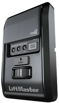 WARNING: This product can expose you to chemicals including lead, which are known to the State of California to cause cancer or birth defects or other reproductive harm. For more information go to www.P65Warnings.ca.gov
INSTALLATION
Install the MyQ® Control Panel in place of the existing door control. Due to power consumption the MyQ® Control Panel cannot be used in conjunction with another wired door control connected to your garage door opener. If an additional door control is needed, the wireless door control model 885LM can be programmed to the MyQ® Control Panel. To program the 885LM to the MyQ® Control Panel, follow the remote control programming steps. When in battery back-up mode, any feature using unattended operation such as Timer-to-Close, closure from a garage door and gate monitor or remote operation utilizing the LiftMaster® Internet Gateway will be disabled.
- Disconnect all electrical and battery power (if applicable) to the garage door opener.
- Remove the existing door control from the wall.
- Note the polarity of the wires connected to the existing door control.
- Label the wire connected to the RED terminal.
- Label the wire connected to the WHITE terminal.
Disconnect the wires from the existing door control.
- Connect the wires to the new MyQ® Control Panel. Make sure the polarity is correct.
- Red wire to the R terminal.
- White wire to the W terminal.
- Mount the MyQ® Control Panel to the wall.
- Reconnect power. The yellow command LED and the red learn LED will blink quickly for up to 5 minutes as the control panel recharges. When the control panel is operational, the yellow command LED will glow steadily.
- To test the control panel, press the push bar to activate the garage door opener.

PROGRAMMING
REMOTE CONTROL
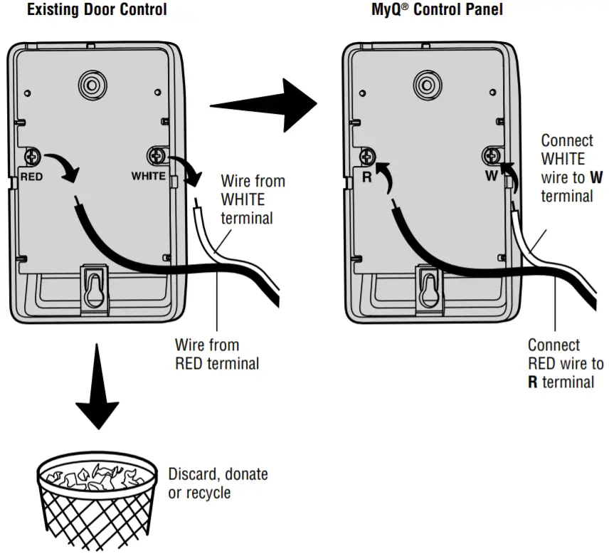
- Press the MyQ® Control Panel LEARN button twice, the red learn LED will turn on.
- Press the button on the remote control that you wish to operate your garage door.
- The garage door opener lights will flash (or two clicks will be heard) when the code has been programmed.
KEYLESS ENTRY
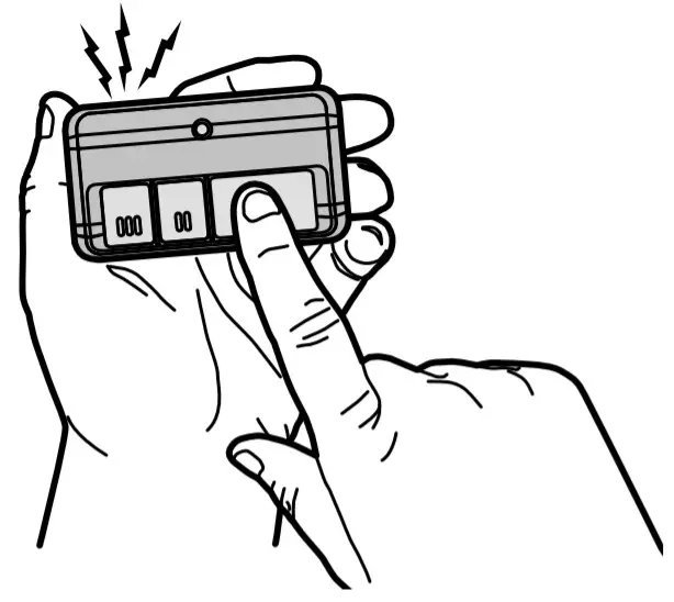
- Press the MyQ® Control Panel LEARN button twice, the red learn LED will turn on.
- Enter a 4-digit personal identification number (PIN) of your choice on the keyless entry keypad. Then press the ENTER button.
- The garage door opener lights will flash (or two clicks will be heard) when the code has been programmed.
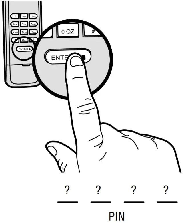
MyQ® ENABLED ACCESSORIES
- Press the MyQ® Control Panel LEARN button twice, the red learn LED will turn on.
- Press the LEARN button on the MyQ® device.*
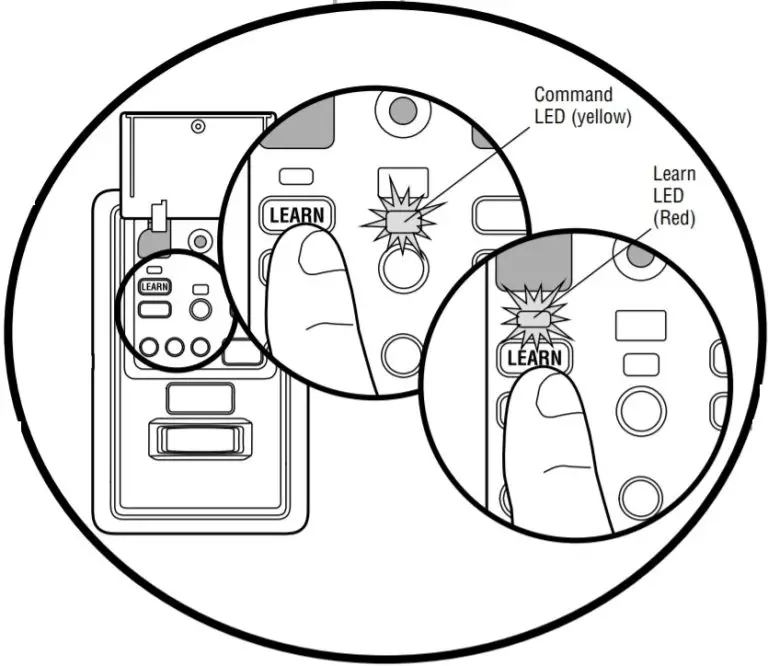
Model 825LM – Remote Light Control
Light module can be synchronized with the garage door opener light bulbs.
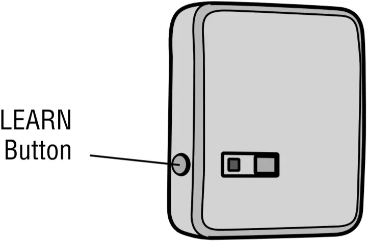
Model 829LM – Garage Door and Gate Monitor
Indicates the status of your garage door from inside the home and allows you to close an open garage door from inside the house.
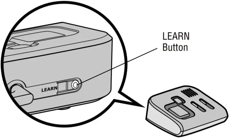
Model 823LM – Remote Light Switch
Light module can be synchronized with the garage door opener light bulbs.
* MyQ® accessories may be programmed to the LiftMaster® Internet Gateway (Model 828LM) or the MyQ® control panel. For instructions on programming to the internet gateway refer to the manual.
INTERNET GATEWAY
The LiftMaster® Internet Gateway gives you control of your garage door from your internet connected computer or mobile device. You must have your internet gateway registered to your customer account at myliftmaster.com in order to use it with the MyQ® Control Panel. Go to myliftmaster.com and follow the instructions to create an account and register your device if you have not already.
To program your control panel to the LiftMaster® Internet Gateway:
- Go to myliftmaster.com from a computer or mobile device.
- Click on “Manage Places>Add New Device>Garage Door Opener” and follow the directions.
- Once you click ADD you have 3 minutes to press the LEARN button two times on the MyQ® control panel. The red learn LED will turn on.
- The red learn LED will turn off when programming is complete. Once the control panel is learned, it will appear on your screen. You can then name the device (e.g., My Control Panel, etc.).
Model 828LM
LiftMaster® Internet Gateway
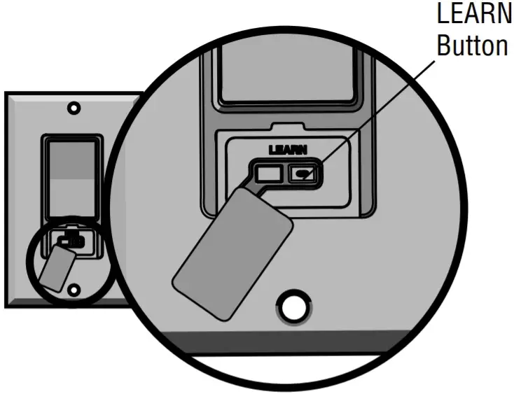
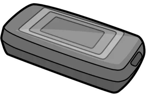
FUNCTIONS
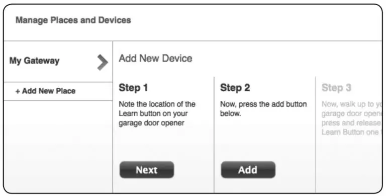
PUSH BAR
Press the push bar to open/close the door.
LIGHTS
Press the LIGHT button to turn the garage door opener lights on or off. When the lights are turned on they will stay on until the LIGHT button is pressed again, or until the garage door opener is activated. Once the garage door opener is activated the lights will turn off after the specified period of time (the factory setting is 4-1/2 minutes). The LIGHT button will not control the lights when the door is in motion.
To change the amount of time the garage door opener lights will stay on: Press and hold the LOCK button until the garage door opener lights flash. The time interval is indicated by the number of flashes.
| NUMBER OF TIMES GARAGE DOOR OPENER LIGHTS FLASH | 1 | 2 | 3 | 4 |
| TIME THE GARAGE DOOR OPENER LIGHT STAYS ON | 1 ½ Minutes |
2 ½ Minutes |
3 ½ Minutes |
4 ½ Minutes |
Light Feature
The lights will turn on when someone enters through the open garage door and the safety reversing sensor infrared beam is broken.
Activate:
Start with the garage door opener lights on. Press and hold the LIGHT button until the garage door opener lights turn off, then on again.*
Deactivate:
Press and hold the LIGHT button until the garage door opener lights turn on, then off again.*
* Approximately 10 seconds
MOTION SENSOR
This feature will automatically turn on the garage door opener lights when motion is sensed. The lights will come on for the set period of time, then shut off.
Activate/Deactivate:
Slide the motion sensor switch ON or OFF.
TIMER-TO-CLOSE (TTC)
NOTE: DO NOT install this door control on garage door opener systems controlling one-piece or swing doors.
The TTC feature automatically closes the door after a specified time period (1, 5, or 10 minutes). Once the TTC has been set and the door is open, the LED for the selected close interval will blink and begin to count down to close the door. The control panel will beep and the garage door opener lights will flash before closing the door.
The TTC feature will deactivate if the garage door encounters an obstruction twice; or the safety reversing sensors are incorrectly installed. The garage door will reverse open and WILL NOT close until the obstructions are clear or the safety reversing sensors are correctly installed. When the obstruction has been cleared or the safety reversing sensors have been aligned, the door will close when the garage door opener is activated.
- Activate:
Press and hold the ON button until one of the TTC LEDs light up. Then press the ON button again to cycle through the time interval options (the corresponding TTC LED will light for each time interval). The garage door opener light bulbs will blink as confirmation. - Deactivate:
Press and hold the OFF button until all TTC LEDs turn off and a beep is heard from the control panel. - Temporarily hold door open (suspend TTC):
Press and release the HOLD OPEN button. The HOLD OPEN button will begin to flash. Press the HOLD OPEN button again to resume normal TTC operation.
LOCK
Activate*:
Press and hold the LOCK button for 2 seconds. The command LED will flash as long as the lock feature is activated and your handheld remote control will not operate your door at this time.
Deactivate:
Press and hold the LOCK button again for 2 seconds. The command LED will stop flashing and normal operation will resume.
- Your LiftMaster® keypad will continue to work when the LOCK has been activated.
ERASE DEVICES FROM MEMORY
Erase all remote controls and keyless entries:
- Press and hold the LEARN button on the control panel until the red learn LED goes out (approximately 6 seconds). All remote control and keyless entry codes are now erased. Reprogram any compatible accessory you wish to use.
NOTE: Erasing remote controls and keyless entries from the control panel does not erase them from the garage door opener, you need to erase the memory of the garage door opener separately.
Erase all devices (including MyQ® enabled accessories):
- Press and hold the LEARN button on the control panel until the red learn LED goes out (approximately 6 seconds).
- Immediately press and hold the LEARN button again until the red learn LED goes out. All codes are now erased. Reprogram any compatible accessory you wish to use.
TROUBLESHOOTING
- If the yellow command LED does not turn on, reverse the wires connected to the R and W terminals of the control panel. Replace wire if necessary.
- If yellow and red LEDs are blinking slowly, the control panel is not compatible with your garage door opener.
- If the yellow and red LEDs are blinking quickly, the control panel is charging, and may take up to 5 minutes to become operational.
WARRANTY
ONE YEAR LIMITED WARRANTY
LiftMaster warrants to the first consumer purchaser of this product that is free from defect in materials and/or workmanship for a period of 1 year from the date of purchase.
Customer Service
FOR SERVICE DIAL OUR TOLL FREE NUMBER:
PHONE: 1-800-528-9131
Website: LiftMaster.com
NOTICE: To comply with FCC and/or Industry Canada (IC) rules, adjustment or modifications of this transceiver are prohibited. THERE ARE NO USER SERVICEABLE PARTS. Any changes or modifications not expressly approved by the party responsible for compliance could void the user’s authority to operate the equipment.
This device complies with Part 15 of the FCC rules and IC RSS-210. Operation is subject to the following two conditions:
- this device may not cause harmful interference, and
- this device must accept any interference received, including interference that may cause undesired operation.
This Class B digital apparatus complies with Canadian ICES-003.
© 2014, LiftMaster
All Rights Reserved