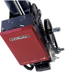
LiftMaster Elite Series Logic 5 T Door Operator User Guide
QuickStart for the model T door operator
This QuickStart is intended to highlight a typical installation. These instructions are not intended to be comprehensive. Since each application is unique, it is the responsibility of the purchaser, designer, installer and end user to ensure that the total door system is safe for its intended use. Please consult the manual and/or a qualified technician for further information.
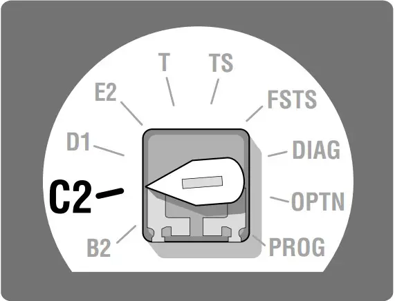
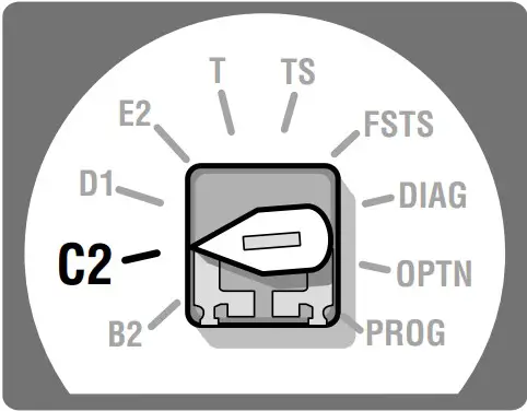
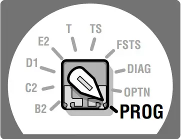
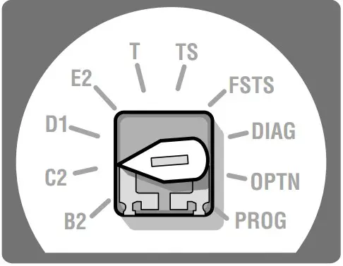
Board Selector Dial Factory Setting is C2*
*See installation manual for full description of modes.
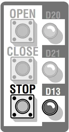
Remote Controls
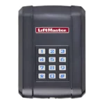
Built in 3-channel, Security 2.0TM radio receiver that allows you to add up to 90 remote control devices and up to 30 keyless entry devices.
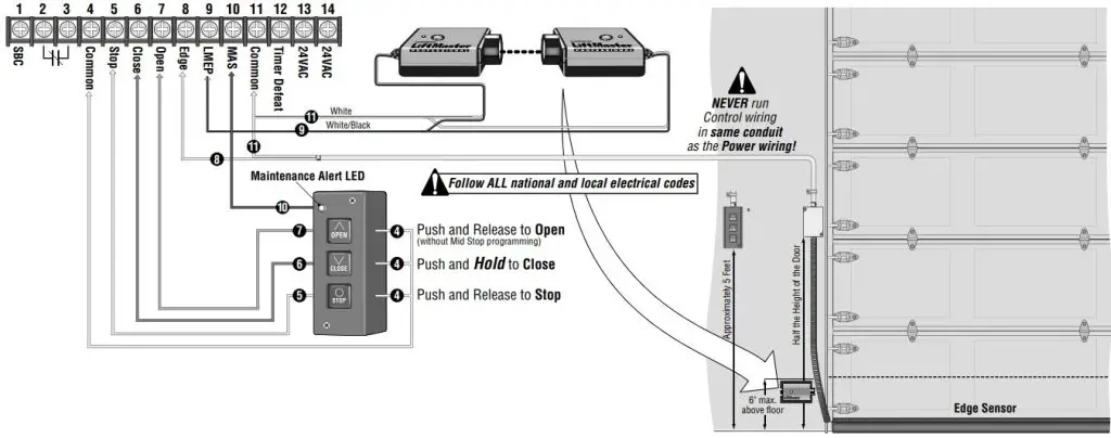
CONTROL WIRING 20 AWG or greater
LiftMaster Monitored Entrapment Protection (LMEP) is required for most programmable settings. Thru-Beam Photoelectric Sensors (Shown)
WARNING: This product can expose you to chemicals including lead, which are known to the State of California to cause cancer or birth defects or other reproductive harm. For more information go to www.P65Warnings.ca.gov
MAS Programming (Maintenance Alert System)
- The MAS assists the installing dealer in setting up a routine maintenance program. Once programmed, the MAS notifies the end user (with a flashing LED on the 3 button station) when a preset number of cycles/months has elapsed and scheduled maintenance is due.
- Close the Door.
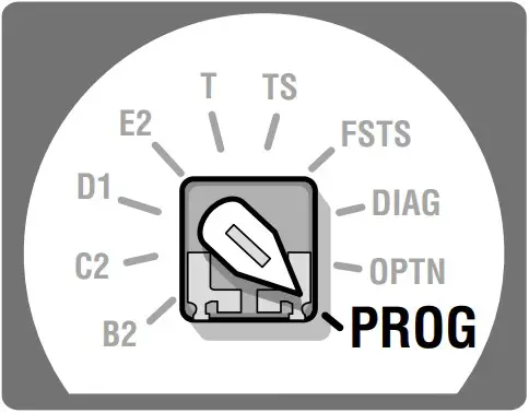
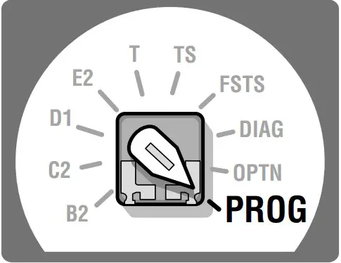
- Turn the selector dial to Program.
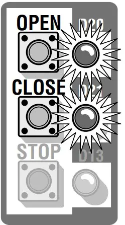
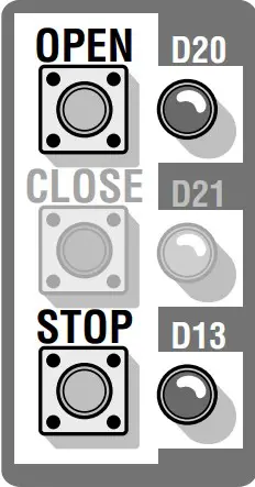
- Press and release the MAS button.
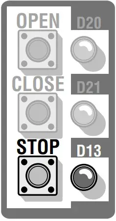
- Press the STOP button once CLOSE D21 to clear the MAS counter.

- Press the OPEN button once for every 5,000 Cycles increments. Press the CLOSE button once for every 3 Month increments. Press the STOP button once to Clear the MAS Setting.
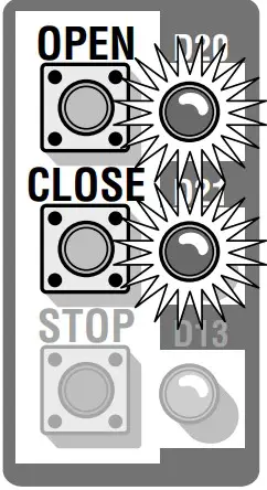
- Press the MAS button to complete the programming. The on board LED will flash back the programmed settings. The OPEN LED will flash once for every 5,000 cycles. The CLOSE LED will flash once for every 3 months.
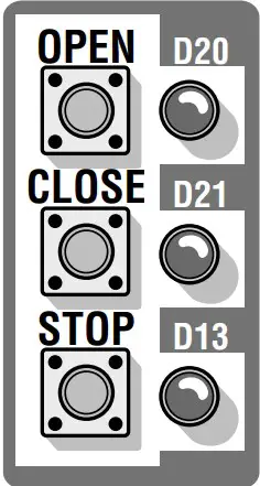
- Turn the selector dial back to the desired wiring type.
Timer-to-Close Programming
Timer automatically closes door after a preset time.
- Close the Door.
- Turn selector to PROG.
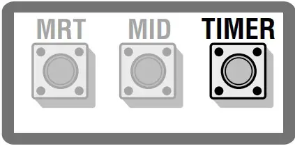
- Press and release the TIMER button.
- Press and release the STOP button to clear the timer.
- Press and release the OPEN button once for every 1 second. Press and release the CLOSE button once for every 15 seconds.
Example: Push CLOSE + Push OPEN + Push OPEN = 17 seconds total (15 seconds) (1 second) (1 second)
- Press and release the TIMER button to complete programming. MRT
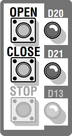 MID TIMER The OPEN LED will flash once for every 1 sec. The CLOSE LED will flash once for every 15 sec.
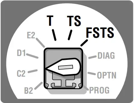
- Turn selector to T, TS or FSTS wiring types.
NOTE: Must have at least one LiftMaster Monitored Entrapment Protection (LMEP) device installed.
OPEN Mid Stop Programming
The mid stop feature is to open the door to a preset point prior to the fully open position.
- Close the Door.
- Turn selector to PROG.
- Press and release the MID button.
- Press the OPEN button, wait until the door reaches the desired mid stop height, then press and release the STOP button.
- Press and release the MID button to complete programming.
- Turn selector back to selected wiring type.
IMPORTANT: This QuickStart is intended to highlight a typical installation. These instructions are not intended to be comprehensive. Since each application is unique, it is the responsibility of the purchaser, designer, installer and end user to ensure that the total door system is safe for its intended use. Please consult the manual and/or a qualified technician for further information.
Inside the Electrical Box

Follow All National and local Electrical codes.
POWER WIRING USE COPPER WIRE ONLY
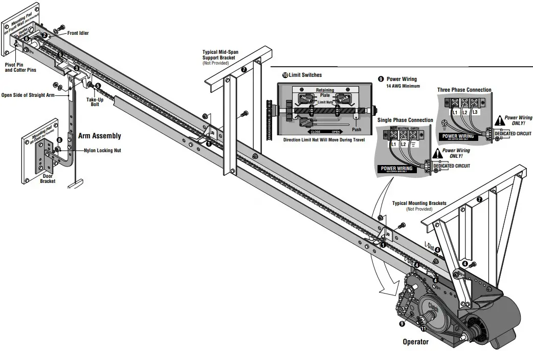
- Install the track spacers down the track (as shown). The nylon pad on the spacer bracket must face up. (Two -1″ bolts/nuts per spacer)
- Install the front idler in the second hole from the end of the track. (Two -1″ bolts/nuts with lock washers)
- Slide the trolley into the tracks so that the take-up bolt will be facing toward the operator.
- Secure the operator to the tracks using the L-slot and the 3rd hole for each track. (Four -1″ bolts/nuts)
- Connect the chain to the trolley carriage connection on the door end. Connect the take-up bolt on the other end and adjust chain accordingly. A properly adjusted chain will sag about 3 inches at the mid-point. If necessary, remove links from the chain to achieve proper adjustment. (Two nuts and a lock washer, two master links)
- Provide a mounting pad for the header bracket to attach to the front wall. Then use the pivot pin and cotter pins to secure the track assembly to the header bracket (with the operator remaining on the floor).
- Secure some mounting brackets to the operator. Pivot the operator up until track assembly is horizontal with the header bracket then secure the brackets to the ceiling. If the track is longer than 15 feet, use of a mid-span support bracket is recommended.
- Assemble the curved and straight arm as shown making sure the open side of the notch on the straight arm faces the door, (Two -1″ bolts/nuts). Attach arm assembly to the door bracket with a 1″ bolt and nylon locking nut so the bolt can pivot.
- Run the power wires through the power wiring conduit hole in the electrical box enclosure. Connect the power to the operator. Connect the earth ground to the ground screw in the electrical box enclosure. Follow ALL national and local electrical codes.
- Adjust the limit switches to open and close door properly. Make sure the limit nuts are positioned between the limit switches before proceeding with adjustments.
- Remove cotter pin from nut on the clutch shaft. Back off clutch nut until there is very little tension on the clutch spring. Tighten clutch nut gradually until there is just enough tension to permit the operator to move the door smoothly but to allow the clutch to slip if the door is obstructed. When the clutch is properly adjusted, it should generally be possible to stop the door by hand during travel. Reinstall cotter pin when finished.
- Radio programming instructions inside cover of operator.