![]()

Quick Start Guide
MMX8x4-HT420M
Important Safety Instructions
Please read the supplied safety instruction document before using the product and keep it available for future reference.
Introduction
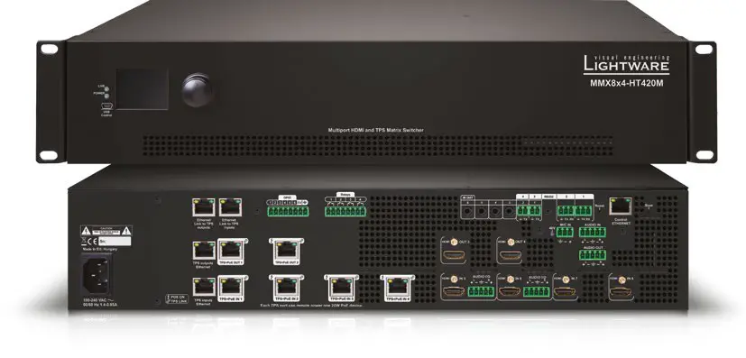
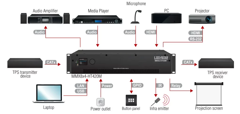
MMX8x4-HT420M is a standalone matrix switcher specifically designed for conference room environments. It has eight video inputs (4x HDMI, 4x TPS) and four video outputs (2x HDMI 2x
TPS). 4K / UHD (30Hz RGB 4:4:4 or 60Hz YCbCr 4:2:0), 3D capabilities, and HDCP are fully supported. MMX8x4-HT420M has a dedicated Special Audio Input block with input ports for microphone and line-in. The built-in sound mixer allows free mixing of the audio signals from the de-embedded HDMI, the microphone or the line-in.
Box Contents
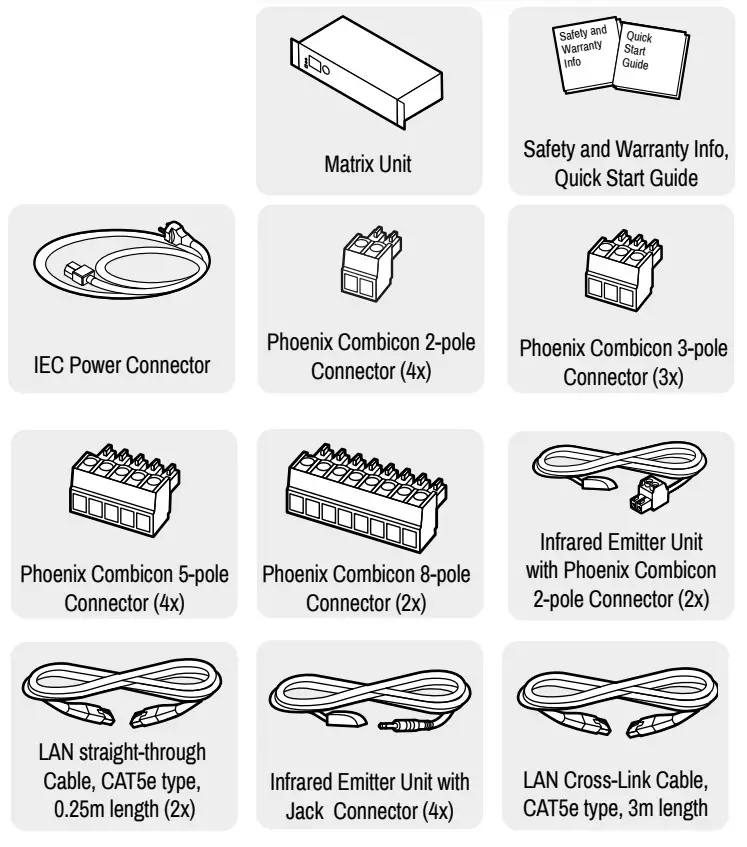
Compatible Devices
The MMX8x4-HT420M matrix is compatible with other Lightware TPS devices, matrix TPS and TPS2 boards, 25G boards, as well as third-party HDBaseT-extenders, but not compatible with the phased out TPS-90 extenders.
HDBaseT TM and the HDBaseT Alliance logo are trademarks of the HDBaseT Alliance.
Front View
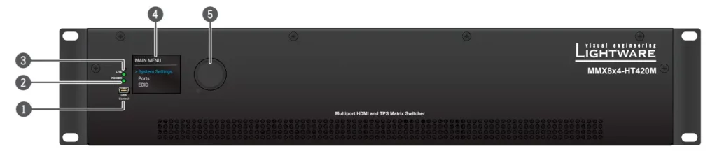
- USB port USB mini-B port for controlling the unit locally by Lightware Device Controller software.
- POWER LED
 on Power LED indicates that the unit is powered on.
 - LIVE LED
 blinking slowly
The unit is on and operates properly.
blinking fast
The unit is in bootload mode. - LCD screen Displays the front panel menu. Basic settings are available.
- Jog dial knob Browse the menu by turning the knob, click on the desired item to check or change it.
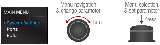
LCD Menu and Navigation
The front panel has a color LCD showing the most important settings and parameters (E.g. network settings, port status, crosspoint state). The jog dial control knob can be used to navigate between the menu items or change the value of a parameter. The knob can be pressed to enter a menu or edit/set a parameter.
Mounting Options – Standard Rack Installation
Two rack ears are supplied with the product, which are fixed on left and right side as shown in the picture. The default position allows mounting the device as a standard rack unit installation.
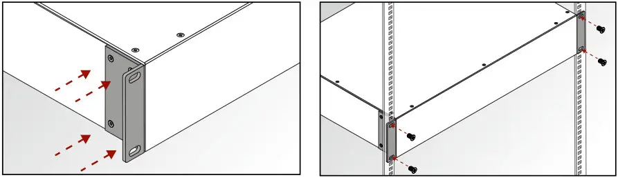
 The matrix switcher is 2U-high and one-rack wide.
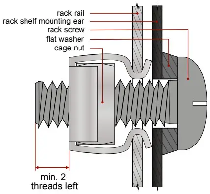
 Always use all four screws for fixing the device ears to the rack rail. Choose proper size screws for mounting. Keep a minimum of two threads left after the nut screw.
Ventilation
To ensure the correct ventilation and avoid overheating let enough free space around the appliance. Do not cover the appliance, let the ventilation holes free on both sides.
Rear View
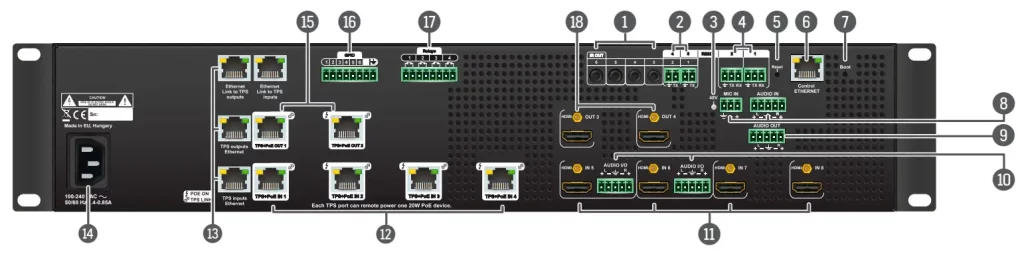
- Infra outputs 3.5 mm TRS (Jack) plugs for infra signal transmission.
- Serial/Infra outputs 2-pole Phoenix connectors (2x) for IR output or TTL output serial signal.
- 48 V LED
 on Phantom power turned on.
 off Phantom power turned off.
 - RS-232 ports 3-pole Phoenix connectors (2x) for bi-directional RS-232 communication.
- Reset button Reset or power on the device while keep pushing the hidden button takes the matrix in bootload mode.
- Ethernet port RJ45 connector to control the matrix via LAN.
- Boot button Reset or power on the device while keep pushing the hidden button takes the matrix in bootload mode.
- Analog audio inputs 3-pole Phoenix connector for microphone input and 5-pole Phoenix connector for balanced analog audio input.
- Analog audio outputs 5-pole Phoenix connector for balanced analog audio; the signal can be mixed from the de-embedded audio of the TPS/HDMI inputs or the microphone input or the line in.
- Audio I/O ports 5-pole Phoenix connector for balanced analog audio; depending on the configuration, it can be input or output. Output audio is the de-embedded HDMI signal from the nearby HDMI port.
- HDMI inputs HDMI input ports (4x) for sources.
- TPS inputs RJ45 connectors (4x) for incoming TPS signal;
- PoE-compliant. TPS Ethernet Locking RJ45 connector to supply Ethernet communication for the TPS lines – it can be separated from the LAN communication (controlling functions) of the matrix. Not PoE-compliant.
- AC connector Standard IEC connector accepting 100-240 V, 50 or 60 Hz.
- TPS outputs RJ45 connectors for TPS signal; PoE-compliant.
- GPIO 8-pole Phoenix connector for configurable general purpose input/output ports.
- Relay 8-pole Phoenix connectors for relay ports.
- HDMI outputs HDMI output connectors for sink devices.
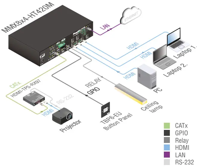
Typical Application Diagram
Factory Default Settings
| IP address | 192.168.0.100 |
| RS-232 port setting | 57600 BAUD, 8, N, 1 |
| Control protocol (RS-232) | LW2 |
| Crosspoint setting | Input 1 on all outputs |
| I/O Ports | Unmuted, unlocked |
| TPS mode | Auto |
| PoE enable | Enable |
| HDCP enable (input) | Enable |
| HDCP mode (output) | Auto |
| Signal Type | Auto |
| Emulated EDID | F47 – (Universal HDMI, all audio) |
| Audio mode | HDMI audio passthrough |
| MIC input levels | Volume (dB): 0.00; Panorama (Balance): 0; Gain (dB): 0.00 |
| Analog audio input levels | Volume (dB): 0.00; Balance: 0; Gain (dB): 0.00 |
| Analog audio output levels | Volume (dB): 0.00; Balance: 0 |
Remote Powering (PoE)
The matrix is PoE-compatible (in accordance with IEEE 802.3af standard) and able to send remote power to connected TPS devices via the TPS connection (through the CATx cable). No local power adaptor is required for the connected PoE-compatible TPS extender. The PoE feature is enabled on TPS ports as factory default.
Installation Guide for Connecting a Microphone

These settings can be done from a computer using the Lightware Device Controller (LDC) software. The application is available at www.lightware.com, install it on a Windows PC or a Mac OS X and connect to the device via LAN, USB, or RS-232.
- Before the connection, please set these properties below:
Port Property Value Lightware Device Controller Analog audio output
(BAL. OUT)Volume -80dB and/or Mute 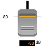

Microphone
input
(MIC IN)Volume -80dB and/or Mute 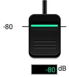
A Skipping the volume or mute setting can cause serious damage in the speaker or the external sound system when phantom power is turned on! Phantom power Turn off A Always turn off the phantom power before connecting the microphone! Port Property Value Lightware Device Controller Microphone input (MIC IN) Input gain -12dB -12 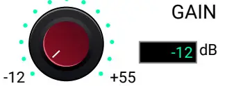
EQ (High,Hmid, Lmid, Low) 0 -18 
Panorama 0 L 
- Connect the microphone.
a. In the case of dynamic or wireless microphones: skip this step and follow the instructions with step 3.
b. In case of condenser microphone: Switch on the phantom power. Keep pressed the +48V button for more than 2 seconds to activate phantom power.
Phantom power supplies the condenser microphone by 48V which is necessary for normal operation. Application of the phantom power can cause damage if the dynamic or wireless microphone is connected!
 Always switch on the phantom power when the cabling and connecting have already been done. Do not disconnect the microphone when the phantom power is switched on!
 - Set these properties below:
Property Value Lightware Device Controller Analog audio output
(BAL.OUT)Volume 0dB 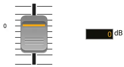
Microphone input
(MIC IN)Volume 0dB 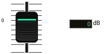
- Talk to the microphone continuously. Increase the microphone input gain slowly and check the signal indicator chart. It gives feedback about the optimal signal level.
Take care that peak led (PK!) never lights up!
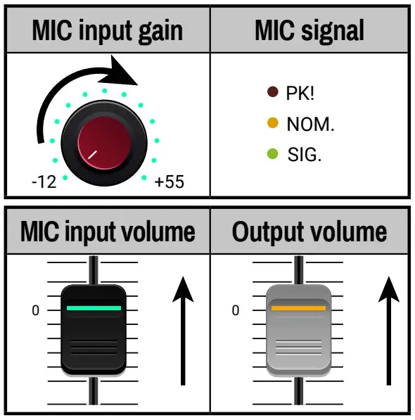
- If the signal level is low, set the optimal volume for both the microphone input and balanced output channel. Always check the signal indicator chart for the optimal level!
Take care that peak led (PK!) never lights up!
Connecting Steps
CATx Connect an HBase-T TM -compatible transmitter or matrix output board to the TPS input port. PoE-compliant.
HDMI Connect an HDMI source (e.g. PC) to the HDMI input port.
HDMI Connect an HDMI sink (e.g projector) to the HDMI output port.
Audio Optionally for analog output port: connect an audio device (e.g. audio amplifier) to the analog audio output port by an audio cable.
Audio See the Installation Guide for Connecting a Microphone section on the left, before connecting the microphone. Not proper setting can cause damage.
Audio Optionally for audio input: connect the audio source (e.g. media player) to the audio input port by an audio cable.
USB Optionally connect the USB cable in order to control the matrix switcher via the
Lightware Device Controller software.
LAN Optionally connect the UTP cable (straight or cross, both are supported) in order to control the matrix switcher via the Lightware Device Controller software.
Relay Optionally for relays: connect a controlled device(s) (e.g. a projection screen) to the relay port.
IR Optionally connect the infra emitter to the infra output port (2-pole Phoenix or 1/8” Stereo Jack connector) to transmit the infra signal.
GPIO Optionally connect a controller/controlled device (e.g. button panel) to the GPIO port.
Power Connect the power cord to the AC power socket to the matrix unit.
Powering the device is recommended as the final step.
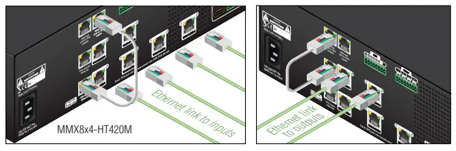
Ethernet Link to TPS inputs and TPS outputs
TPS lines do not transmit Ethernet signals, but they can be transmitted on the TPS input and output ports if there is a physical link between the motherboard and the input or the output board. This makes it possible to control a third-party device or supply Ethernet via TPS.
Connect a patch cable between
- Ethernet Link to TPS inputs and TPS inputs Ethernet labeled RJ45 connectors or
- Ethernet Link to TPS outputs and TPS outputs Ethernet labeled RJ45 connectors to create a link.
Maximum Extension Distances
| Resolution | Pixel clock rate |
Cable lengths (Auto I Long reach TPS mode) |
||
| CAT5e AWG24 |
CAT7 AWG26 |
CAT7 AWG23 |
||
| 1024×768®60Hz | 65 MHz | 100 ml 130 m* | 90 m / 120 m* | 120 m 1170 m* |
| 1280x720p®60Hz | 73.8 MHz | 100 m 1130 m* | 90 m 1120 ms | 120 m 1170 m* |
| 1920x1080p®60Hz (24bpp) | 148.5 MHz | 100 m 1130 m* | 90 m 1120 ms | 120 m 1170 m* |
| 1920×1200®60Hz | 152.9 MHz | 100 m I NA | 90 m I NA | 120 m I NA |
| 1600×1200®60Hz | 162 MHz | 100 m / NA | 90 m I NA | 120 m I NA |
| 1920×1080®60Hz (36bpp) | 223 MHz | 70 m I NA | 70 m I NA | 100 m I NA |
| 3840×2160®30Hz UHD | 297 MHz | 70 m I NA | 70 m I NA | 100 m I NA |
| 4096×2160®30Hz 4K | 297 MHz | 70 m I NA | 70 m I NA | 100 m I NA |
* Long reach TPS mode supports pixel clock frequencies up to 148.5 MHz.
To specify the accurate extension distances, please also check the documentation of the connected TPS device.
![]() CAT7 SFTP AWG23 cable is always recommended.
CAT7 SFTP AWG23 cable is always recommended.
Wiring Guide for RS-232 Data Transmission
MMX8x4 series matrix is built with a 3-pole Phoenix connector. See the below examples of connecting to a DCE (Data Circuit-terminating Equipment) or a DTE (Data
Terminal Equipment) type device:
![]()
For more information about the cable, wiring see the user’s manual of the device or Cable Wiring Guide on our website www.lightware.com/support/guides-and-white-papers.
Audio Cable Wiring Guide
MMX8x4 series matrix is built with 5-pole Phoenix input and output connectors. See below a few examples of the most common assembling cases.
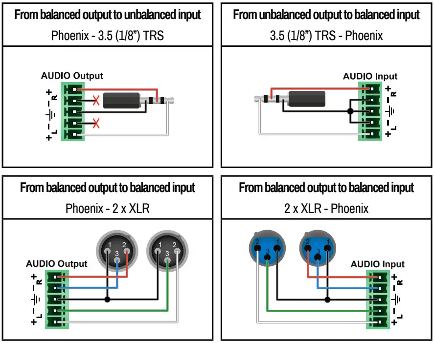
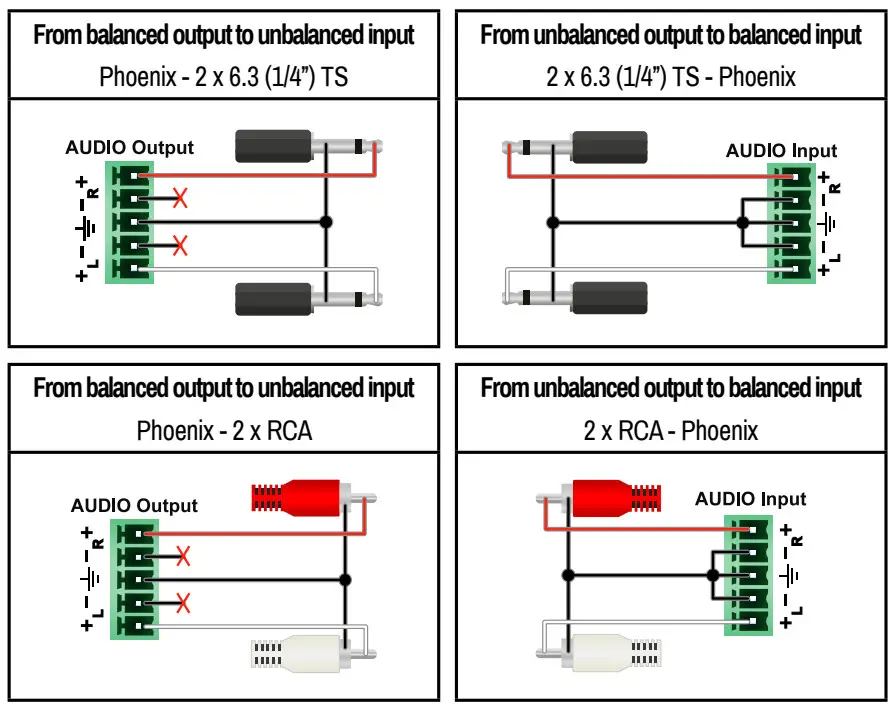
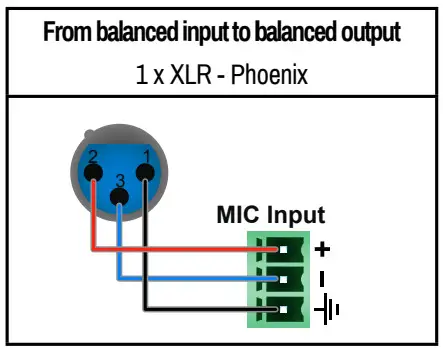
Always check the correct wiring of the microphone cable! Never apply phantom power with an unbalanced cable, because it can cause damage!
Microphone cable should be shielded with 2×0,22mm conductor, max. 50m long.
For more information about audio cable, wiring see the user’s manual of the device or the Cable Wiring Guide on our website www.lightware.com.
Serial Output Voltage Levels (TTL and RS-232)
| TTL* | RS-232 | |
| Logic low level | 0 .. 0.25V | 3V..15V |
| Logic high level | 4.75 .. 5.0V | -15 V .. -3 V |
*Using a receiver with at least 1k impedance to any voltage between 0V and 5V to get the voltages, but not compatible with the phased-out TPS-90 extenders.
Further Information
The document is valid with the following firmware version: 1.0.1
The User’s manual of this appliance is available on www.lightware.com.
See the Downloads section on the website of the product.
Contact Us
[email protected]
+36 1 255 3800
[email protected]
+36 1 255 3810
Lightware Visual Engineering LLC.
Peterdy 15, Budapest H-1071, Hungary
Doc. ver.: 1.3
19200104