
![]()
Smart WI-FI Garage Door Opener
DC motor with LED lighting and belt- or chain-drive rail
Battery Backup Capable
LDCO 841/863
Manufactured by:
Nortek Security & Control LLC
USA & Canada (800) 421-1587
www.nortekcontrol.com
Installation instructions
For Sectional Type Doors
IMPORTANT SAFETY NOTES
Please read the instructions carefully! This garage door operator is designed to provide safe and reliable service if installed and tested as described in these instructions.A garage door is the largest mechanical appliance in a residence. Care must be taken to prevent injury or death during the installation and operation of the garage door and garage door operator.
WARNING
This type of warning note is used to indicate possible electrical shock hazards that may cause serious injuries or death.
THE FOLLOWING FORMATS ARE USED FOR SAFETY NOTES IN THESE INSTRUCTIONS.
 WARNING
This type of warning note is used to indicate possible mechanical hazards that may cause serious injuries or death.
CAUTION
This type of warning note is used to indicate the possibility of damage to the garage door or garage door operator.
IMPORTANT INSTALLATION SAFETY INSTRUCTIONS
WARNING
TO REDUCE THE RISK OF SEVERE INJURY OR DEATH TO PERSONS, REVIEW THESE INSTALLATION SAFETY STEPS BEFORE PROCEEDING
- READ AND FOLLOW ALL INSTALLATION INSTRUCTIONS.
- Install only on a properly balanced sectional garage door. An improperly balanced door could result in severe injury or death. Repairs to cables, spring assemblies, and other hardware must be made by a qualified service person before installing the opener.
- Disable all locks and remove all ropes connected to the garage door before installing the opener. Ropes connected to a garage door can cause entanglement and death.
- If possible, install door opener 7 feet or more above the floor with the manual release handle mounted 6 feet above the floor.
- Do not connect the opener to the power source until instructed to do so.
- Locate the wall station or push button within sight of the door at a minimum height of 5 feet so that small children cannot reach it. Locate the wall station or push the button away from all moving parts of the door.
- Install the User Safety Label on the wall adjacent to the wall station or push the button.
- Upon completion of the installation, the door must reverse when it comes in contact with a 1-1/2” high object (or a 2×4 laid flat at the center of the door) on the floor and when the infrared safety beam is blocked.
- Do not wear watches, rings or loose clothing while installing or servicing an opener. Jewelry or loose clothing can be caught in the mechanism of the garage door or the opener.
- DISCONNECT THE ELECTRIC POWER FROM THE GARAGE DOOR Opener BEFORE MAKING ANY REPAIRS OR REMOVING THE COVER.
- Disconnecting the Door from the Opener: With the door in any position (preferably closed), carefully pull the red release handle. USE CAUTION IF THE DOOR IS OPEN. An open or partially open door may fall rapidly if disconnected from the opener. Do not allow anyone in the path of the door.
- Use this operator only with a sectional overhead door no more than 10FT tall.
Check the Door Balance
- From outside the garage, slowly open the door all the way, and then close it all the way. Notice if there is any binding, sticking or rubbing. The door should move smoothly in both directions.
- Raise the garage door about halfway up. Carefully release the door and see if the door balances. It should stay in place. Close the door.
IMPORTANT: If the garage door is unbalanced or the door travel isn’t smooth, have a qualified garage door professional adjust or repair the door.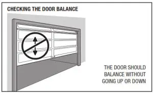
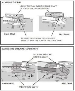
Attach the Rail to the Operator
- Place the operator head on the garage floor with cardboard underneath it to protect the finish.
- Align the rail over the center of the operator’s head.
- Be sure the flat on the sprocket lines up with the flat on the drive shaft.
- Slide the sprocket onto the shaft.
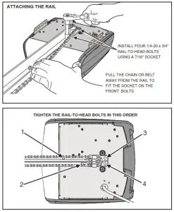
- Attach the rail to the operator’s head by installing four ¼-20 x ¾” bolts.
- Tighten the four bolts in the order shown with a 7/16” socket.
 |
 |
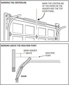
Locate the Header Bracket Position
- Close the door.
- From inside the garage, use a pencil to mark the vertical centerline of the door on the header wall and on the top panel of the door.
- Examine the area above the center of the door on the door header wall for a header bracket mounting location.
- Open the door to the high-rise point (the point where the top edge of the door is highest above the floor) and measure the distance to the floor.
- Close the door and use a pencil to mark the header wall 1” above the measured high-rise point.
NOTE: In some installations, the header bracket location will be higher than the door header. This will require adding a 2×4 (or larger) cross piece to the wall studs to provide a mounting location for the header bracket. Use lag screws (not supplied) to attach the 2×4 to the studs. - On doors with low headroom, the header bracket can be attached to the ceiling up to 6” back from the header wall (see next step).
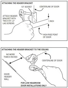
Install the Header Bracket
Attaching the Header Bracket to the Wall
- Hold the header bracket on the centerline drawn above the door with the bottom edge of the bracket on the line marked above the high-rise point.
- Use a pencil to mark the two bracket holes.
- Drill two 3/16” pilot holes about 2” deep.
- Use a ½” socket to fasten the bracket with two 5/16” x 2” lag screws.
Attaching the Header Bracket to the Ceiling
NOTE: On a finished ceiling, be sure there is a joist to fasten to under the sheetrock where the header bracket will be located (use a stud finder). If there is none, install a 2×4 crosspiece between the two closest joists to fasten the header bracket onto.
- Extend the centerline drawn on the header wall along with the ceiling.
- Hold the bracket on the centerline with the edge of the bracket no further than 6” from the header wall.
- Use a pencil to mark the two bracket holes.
- Drill two 3/16” pilot holes about 2” deep.
- Use a ½” socket to fasten the bracket with two 5/16” x 2” lag screws.
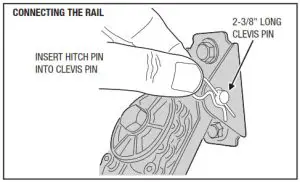
Connect the Rail to the Header Bracket
- Place assembled operator on the empty carton on the floor with rail towards the door.
- Insert the end of the rail into the header bracket.
- Insert the 5/16” x 2-3/8” clevis pin through the header bracket and rail.
- Secure the clevis pin with the hitch pin.
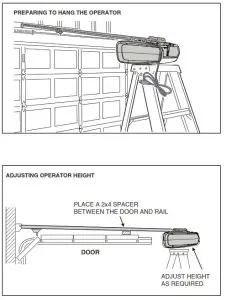
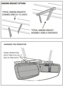
Hang the Operator
Installation requirements vary with garage construction. Hanging brackets should be angled to provide rigid support. Hanging material is not provided. Angle iron and lag screws are recommended. DO NOT USE NAILS. Following are typical operator hanging methods. Certain installations will require improvised methods.
- Raise the operator’s head and set it on top of a stepladder (use extra spacers on top of ladder if it isn’t tall enough).
- Carefully open the door to the full-up position. Lay a 2×4 across the top section of the door as a spacer. Adjust the operator height until the rail touches the spacer. The rail should be close to level.
- Center the operator’s head and rail with the centerline mark on the top of the door.
- For finished ceilings only: An angle iron crosspiece between the two closest joists above the operator will be required. Mark mounting hole locations, drill pilot holes and attach the piece with two lag screws (not supplied).
- Measure the distance from each of the operator’s hanging tabs to the ceiling joists or angle iron crosspiece.
- Cut two-angle iron pieces to the required lengths for hanging brackets. Bend brackets if required.
• For unfinished ceilings: Hold each bracket in place and use a pencil to mark the locations where they will be attached to the joists, drill pilot holes and attach the pieces with two lag screws (not supplied).
• For finished ceilings with an angle iron cross piece: Attach the two hanging brackets to the crosspiece with two bolts and two keps nuts (not supplied). - Attach operator to hanging brackets using two 5/16-18 x 1” hex bolts and two 5/16-18 keps nuts (supplied). Insert bolts from the inside of hanger brackets with the nuts on the outside of the operator. Tighten nuts with a ½” socket.
- Tighten all hanging hardware.
- Open and close the door manually. The door should clear the rail by at least 1”.
- Attach the trolley’s release lever to the red release handle with the cord supplied so the handle is at least 6 feet from the floor. Cut off any excess cord.
WARNING
Children operating or playing with a garage door operator can injure themselves or others. The garage door could cause serious injury or death. Do not allow children to operate the remote control(s) or the wall station. Install the wall station out of reach of children and away from all moving parts of the door. The door must be clearly visible from the wall station. A moving garage door could injure someone under it. Only activate the door when it is properly adjusted, when it can be seen clearly and when there are no obstructions to the door travel.
Install the Wall Station
NOTE: 22 AWG 2-conductor wall station and safety beam wire is supplied with the operator, Use this wire or the installation’s pre-wiring. For additional wire, contact Linear for information regarding the 24-pack Model HAE00009 wire and wire clip kit.
UL NOTE: All low voltage Class 2 cables used with this operator must be UL Listed Type CL2, CL2P, CL2R, or CL2X or another cable with equivalent or better electrical, mechanical, and flammability ratings.
- It is paramount that the Smart Control Wall Station receives a strong signal from your home’s Wi-Fi router. Before you affix the Wall Station to the wall, survey your location to check the Wi-Fi signal. To do this, take a smartphone, connect it to your Wi-Fi network and then place your phone on the wall where you want to attach the Wall Station.
If you have 2 or 3 bars on your phone for the Wi-Fi network, the signal is strong and you can proceed. If not, use one of these options to extend your Wi-Fi network’s range.
• Move your Wi-Fi router closer to the garage.
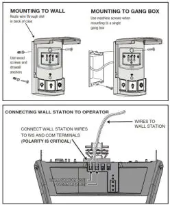
• Purchase a Wi-Fi range extender. - Strip back ½” of insulation and connect a wire to each of the two terminals on the back of the wall station. NOTE: Polarity is CRITICAL.
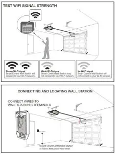
- Use the screws provided to mount the wall station near an access door at a minimum height of five feet. SEE THE IMPORTANT WARNING ABOVE!
- For non-prewired installations, route the wire to the back of the operator. Use insulated staples (not
supplied) to secure the wire. Staples must straddle both wires to avoid electrical shorts. - Cut the wall station wire about 6” longer than needed to reach the operator terminals. Strip back ½” of insulation.
- Connect wires to the operator’s WALL STATION terminal COMMON terminal. Polarity is CRITICAL.
- Apply the User Safety Instruction Label to the wall next to the wall station. Use staples or tacks to help the label remain in place over time.
IMPORTANT! DO NOT PLUG THE OPERATOR IN AT THIS TIME! More installation is required.
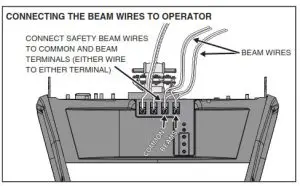
Install the Safety Beam
NOTE: The safety beam’s infrared light beam must not be obstructed by the door, or by any part of the door hardware. Use wooden spacers between the beam brackets and wall if necessary to create proper clearance.
WARNING
Persons, particularly children, could be killed by a closing garage door without a properly installed and adjusted safety beam optical obstacle sensing system.
WARNING
To protect small children, do not install the safety beam higher or lower than instructed.
- Assemble the two safety beam brackets from the four L-shaped brackets using two ¼-20 x ¾” bolts and ¼-20 keeps nuts (one nut & bolt for each bracket).
- Position the assembled brackets on each side of the door so the centerline of the safety beam lenses will be 5-1/2” above the floor. Use the index marks on the brackets to make the bracket assemblies equal lengths. Mark the locations for the bracket mounting screws.
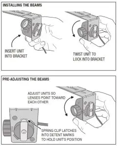
NOTE: The safety beam receiver (the unit with two indicators) should be located on the “shady” side of the door to prevent sunlight from shining directly into the receiver’s lens. - Drill two 3/16” pilot holes for lag screws at marks. Mount the brackets with two ¼” x 1-¼” lag screws and tighten with a 7/16” socket.
- Insert the sender and receiver into the bracket holes so the lenses of the units will face each other. Twist the units until the spring clips lock into a detent mark on the brackets. To protect the units from being bumped after installation, it is recommended to mount the sender and receiver inside the brackets as shown.
• IMPORTANT: Be careful to route the safety beam wiring away from any moving parts of the door or operator. - For non-prewired installations, route the wires from the sender and receiver, up the wall above the door hardware, then over to the center of the door, then along the top of the rail (or ceiling), and back to the operator’s head. Cut the wires about 6” longer than needed to reach the operator terminals. Strip back ½” of insulation from the ends of the wires.
- For non-prewired installations secure all the wires to the wall and ceiling with insulated staples (not supplied). Staples must straddle both wires to prevent shorts. Secure the wire to the top of the rail with wire clips (supplied).
- At the operator, twist one wire from each pair together, then twist the other wire from each pair together.
- Attach either twisted connection to the operator’s BEAM terminal. Connect the other twisted connection to the operator’s COMMON terminal.
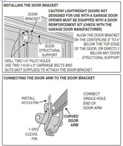
Install the Door Bracket and Door Arm
- Fully close the door. Hold the door bracket against the inside of the door’s top panel. Align the top edge of the bracket 2” to 4” below the top edge of the door; or, if there is structural support across the top of the door, place the top edge of the bracket directly below the support. Align the vertical centerline drawn on the door with the center of the bracket. See the figure for details. Mark the left and right holes of the bracket.
- Drill ¼” holes at marks and insert two ¼-20 x 2” carriage bolts (not supplied) from outside of door through the door bracket.
- Secure door bracket with two ¼-20 keps nuts (not supplied). Tighten with a 7/16” socket.
- Slide the 5/16” x 1-3/8” clevis pin through one hole on door bracket; then the single hole on the curved door arm; then through the other hole on the door bracket. Secure the clevis pin with the hitch pin.
- Insert the single hole end of the straight door arm into the slot in the trolley. Slide the 1-1/8” clevis pin through the hole and secure it with a hitch pin.
- Flip the trolley release lever to disconnect the trolley.
- Rotate the curved door arm upward to meet the straight door arm connected to the trolley. Align the two-door arms so that the holes in both arms overlap.
NOTE: The straight door arm should be slightly angled toward the operator’s head.
CONNECTING DOOR ARMS - Line up door arms until the trolley is positioned as shown. Connect the arms together using two 5/1618 x 1” bolts inserted in the highest and lowest matching
holes,secure the bolts with two 5/16” keeps nuts, tighten with a ½” socket.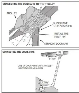
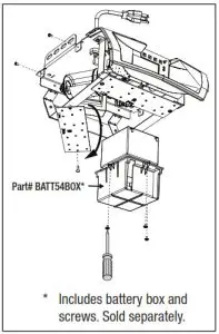
Installing/Replacing the Battery Back-Up
(Applicable Models Sold Separately)
- Loosen the four (4) housing screws and remove the housing.
- Remove one (1) screw from the LED panel beneath the battery box, and carefully swing it out of the way (LDCO 863 model only).
- If replacing the battery backup unit, remove the three (3) screws holding the battery box and remove them.4 Insert the battery into the battery box and install/re-install the box using the three (3) battery box screws.
- Connect the battery terminal wires to the battery terminals. Make sure the RED wire is connected to the POSITIVE terminal and the BLACK wire is connected to the NEGATIVE terminal. Once connected, the operator will beep and the LEDs will illuminate. The operator is now operational.
- Reposition and secure the LED panel.
- Replace the operator housing and tighten the four (4) screws to secure the housing.
Connect the Operator to Power Source
 WARNING
- To prevent electrocution or fire, installation and wiring must be in compliance with local electrical and building codes.
- To reduce the risk of electric shock, this equipment has a grounding-type plug, that has a third (grounding) pin. This plug will only fit into a grounding-type outlet. If the plug does not fit into the outlet, contact a qualified electrician to install the proper outlet. Do not change the plugin anyway.
- Never use an extension cord or change the plugin anyway.
- This product is only intended for use with the supplied power cord. If a suitable grounded outlet can not be reached with the supplied power cord, contact a licensed electrical contractor to install an outlet.
Cord and Outlet Connection
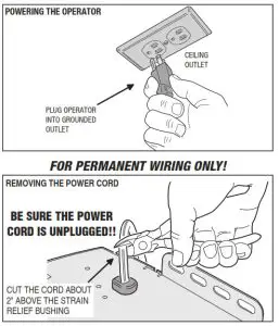
The operator should be connected to a grounded receptacle on the ceiling or near the operator’s head. If none is available which will accept the grounded operator plug, one should be installed by a qualified electrician. Do not use an extension cord.
- Plug the operator into a grounded receptacle.
- When the operator is plugged in, a click should sound in the operator and the light should turn on. If the light does not turn on, check the power source and light bulb.
Permanent Wiring
SOME LOCAL ELECTRICAL CODES REQUIRE PERMANENT WIRING BETWEEN THE OPERATOR AND THE POWER SOURCE THROUGH A CONDUIT. IT IS RECOMMENDED THAT YOU HAVE A LICENSED ELECTRICAL CONTRACTOR FOLLOW THESE STEPS ONLY IF PERMANENT WIRING IS REQUIRED.
- BE SURE THE POWER CORD IS UNPLUGGED.
- Cut the power cord about 2” above the strain relief bushing on the operator.
- Remove the four side screws and bottom cover of the operator.
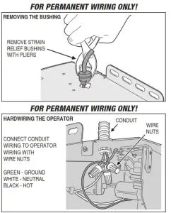
- Use pliers to remove the strain relief bushing and discard the bushing.
- Remove the outer insulation from the power cord and strip the white, black, and green wire insulation back about ½”.
- Pull white (neutral), black (hot) and green (ground) wires through conduit.
- Connect the conduit to the operator with the appropriate termination.
- Use wire nuts (not supplied) to connect the wires to the matching color wires inside the operator’s head.
- Secure the wires away from all moving parts with a zip-tie as shown in the figure.
- Replace the operator cover and the four side screws.
- Connect the conduit wires to the power source at the junction box.
- When power is applied to the operator, a click should sound and the light should turn on. If the light does not turn on, check the power source and wiring.
Aligning the Infrared Safety Beam
The safety beam has two components, a sender and a receiver. The sender produces a narrow infrared beam that travels across the bottom of the door opening to the infrared receiver. If an object blocks the infrared beam while the door is closing, the door will stop, then reverse and fully open (the operator’s light will flash three times). As a safety feature, the operator will ignore signals from all remote controls if the door is open and the infrared safety beam is blocked or out of alignment. In this case, the door can be forced closed by pressing and holding the wall station’s up/down arrow pushbutton (be sure the door area is in clear view).
WARNING
With the door closed, disengage the trolley from the chain or belt during these alignment tests by pulling the red release handle.
WARNING
Serious injury or death from a closing garage door may result because of failure to test and adjust safety reverse system. Repeat this test monthly and adjust as needed.
Safety Beam Test
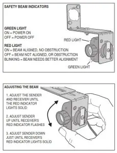
- Check that the operator has power. The green lights on the sender and receiver should be lit.
- If the receiver’s green light is on, but the red light is off, the receiver has power but is not detecting the infrared beam from the sender. The red light might flash when the beam is partially detected. This can be caused by misalignment or something blocking the beam. Adjust the safety beam sender and receiver while watching the receiver’s red light (stay out of the beam while aligning it). When the red light stays on, rotate the sender towards the ceiling and stop when the red light on the receiver begins to flicker. Rotate the sender back towards a horizontal position with the floor and stop as soon as the red light on the receiver lights solid. The beam is now properly aligned.
SAFETY BEAM INDICATOR TABLE GREEN ON POWER ON GREEN OFF POWER OFF RED ON BEAM OK – NO BLOCKAGE RED OFF BEAM BLOCKED OR MIS-ALIGNED RED FLICKERING BEAM ALIGNED POORLY NOTE: If the receiver’s red light remains off, check for: 1) Dirt on the receiver’s lens, 2) Sunlight shining into the receiver’s lens, 3) A short in the safety beam wiring (from staples or at the operator terminals).
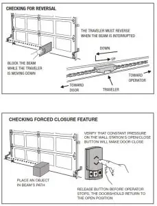
- With the door closed and the operator disengaged from the door, press the wall station’s UP/DOWN ARROW button to move the traveler (the part on the belt or chain that the trolley engages with) to the up position (away from the door). NOTE: Do not cycle the operator to full travel without the door connected.
- Push the wall station’s UP/DOWN ARROW button again. While the traveler is moving to the down position (toward the door), block the safety beam. THE TRAVELER MUST STOP, THEN REVERSE TO THE UP POSITION. The operator’s light and red light should flash three times.
- Place an object in the path of the safety beam. Check that constant pressure is required on the wall station’s UP/DOWN ARROW button to cause the traveler to move toward the down position. Release the pushbutton before the operator stops; check that the traveler returns to the up position.
NOTE: The garage door operator will not respond to a CLOSE command from a radio transmitter if The safety beam is blocked. - To reconnect the operator, flip the release lever up. Raise the door manually until the operator reconnects.
Adjusting the Open and Close Limits
The limit settings control how far the door will open and close. Set the limits so the door opens just short of any door stops, and closes at the floor level. Out of the box, the operator is preset on its close limit and the open limit is preset for a typical 7-foot high door.
Use the wall station or a transmitter to test operate the door.If required, use the following steps to adjust the limits.
CAUTION
Set the open and close limits carefully. Setting the limits beyond the distance that the door can travel could cause damage to the door, the door hardware, or the operator.
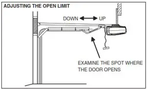
Adjusting the Open Limit
- Use the wall station or remote control to move the door to the open limit position.
- On the back of the opener, press both the UP andLEARN buttons for three seconds. The green indicator and opener’s light will flash twice then stay on.
- Use the UP and DOWN buttons to jog the door at a slow speed to fine-tune the open limit position.
- When the door is at the proper open limit position, press the LEARN button to store the setting and exit setup. The green indicator and the opener’s light will flash two times.
Adjusting the Close Limit
- Use the wall station or remote control to move the door to the close limit position.
- On the back of the opener, press both the DOWN and LEARN buttons for three seconds. The RED LED and opener’s light will flash twice then stay on.
- Use the UP and DOWN buttons to move the door at slow speed to fine-tune the close limit position.
- When the door is at the proper close limit position, press the LEARN button to store the setting and exit setup. The RED LED and the opener’s light will flash two times.
NOTE: If the operator is field reset per Section 20, both the open and close limits must be adjusted and the automatic door force setup must be completed for proper operation. 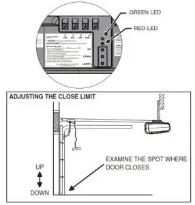
Automatic Door Force Setup
The operator automatically measures the door force throughout the entire travel of the door each time the operator cycles. The following steps are all that is required to set up the safety reversal system.
Automatic Door Force Setup
- Be sure that the trolley latch is up and the door is connected to the operator.
- Operate the door through four complete open and close cycles.
CAUTION
Do not cycle the operator full travel without the door connected. The automatic door force setting will adjust to the unloaded condition and may trip the safety system when the door is reconnected.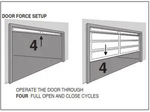
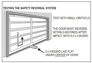
Safety Reversal System Test
The operator determines that there is obstruction if a higher than expected amount of force is detected during a door cycle. If an obstruction is encountered during a closing cycle, the operator and door will stop then fully open. If an obstruction is encountered during an opening cycle, the operator and door will stop.
Safety Reversal System Test
- Lay a 2 x 4 board flat on the floor where it will be struck by the center of the door as it closes.
- Verify that the door reverses when it strikes the board. The door must reverse within two seconds after striking the board.
WARNING
Always perform the Safety Reversal System Test after making any adjustments to the operator.
PERFORM THE SAFETY REVERSAL SYSTEM TEST MONTHLY!
Adjusting the Force Factor (Installation Option, Normally Not Used)
The operator uses the peak force measured during each of the last four complete cycles plus a “force factor” to calculate the maximum allowed force setting for the current door cycle. If the calculated maximum force setting is exceeded during the current door cycle, the operator reacts to the obstruction. As door hardware conditions change over time with weather and wear, the calculation of the maximum door force setting using the four-cycle running average will compensate for the current conditions of the installation.
The door force is preset for the lowest amount of pressure on an obstacle to detecting an obstruction. THE FACTORY SETTING IS OPTIMIZED FOR MOST INSTALLATIONS.
Changing the Force Factor Setting
As an installation option, the operator’s “force factor” can be adjusted to change the amount of pressure exerted on an obstacle before the operator reacts to the obstruction.
- Press both the UP and DOWN buttons for three seconds. The red and green indicators and operator’s light will flash twice.
- Use the UP or DOWN buttons to set the force factor.
Pressing the UP button increases the force factor, pressing the DOWN button decreases the force factor.FORCE FACTOR INDICATOR TABLE GREEN ON LOW FORCE FACTOR RED & GREEN ON MEDIUM FORCE FACTOR RED ON HIGH FORCE FACTOR - After selecting the force factor, press the LEARN button to store the setting and exit setup. The red and green indicators and the operator’s light will flash two times. (If the force factor is not set within one minute, the operator will return to normal operation at its previous force factor setting.)
- After changing the force factor setting, perform the Safety System Reversal Test.
Using the Garage Door Operator
IMPORTANT USER SAFETY INSTRUCTIONS
WARNING
A MOVING GARAGE DOOR CAN CAUSE INJURY OR DEATH!
TO REDUCE THE RISK OF DEATH OR SEVERE INJURY:
- READ AND FOLLOW ALL INSTALLATION INSTRUCTIONS.
- NEVER LET CHILDREN OPERATE, OR PLAY WITH DOOR CONTROLS! KEEP REMOTE CONTROL AWAY FROM CHILDREN!
- Always keep the moving door in sight and away from people and objects until it is completely closed.
NO ONE SHOULD CROSS THE PATH OF THE MOVING DOOR. - NEVER GO UNDER A STOPPED, PARTIALLY OPEN DOOR.
- Test door operator monthly. The garage door MUST reverse on contact with a 1-1/2 inch object (or a 2×4 board laid flat at the center of the door) on the floor. If adjusting either the force or the limit of travel, re-test the door operator. Failure to adjust the operator properly may cause severe injury or death.
- If possible, use the red emergency release handle only when the door is closed. Use caution when using this release with the door open. Weak or broken springs may cause the door to fall rapidly, causing injury or death.
- KEEP GARAGE DOORS PROPERLY BALANCED. (See Garage Door Operator Maintenance) An improperly balanced door could cause severe injury or death. Have a qualified service person make repairs to cables, spring assembly and other hardware.
- This operating system is equipped with an unattended operation feature. The door could move unexpectedly. NO ONE SHOULD CROSS THE PATH OF THE MOVING DOOR. Only use the Smart Control wall station for unattended operation when installed with a sectional residential overhead door.
- SAVE THESE INSTRUCTIONS.
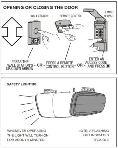
Opening the Door
- With the door in view, press the wall station’s UP/ DOWN ARROW button or the button assigned to the operator on the remote control, or enter a valid access code and press START/STOP on a remote keypad.
- When the operator is activated, the operator’s light will turn on and the door will begin to open.
- The door will open until the open limit is reached. If an obstacle is encountered (operator’s light flashes four times) while the door is opening, the door will stop.
- The operator’s light will stay on for about five minutes after the door stops.
Closing the Door
- With the door in view, press the wall station’s UP/ DOWN ARROW button or the button assigned to the operator on the remote control, or enter a valid access code and press START/STOP on a remote keypad.
- When the operator is activated, the operator’s light will turn on and the door will begin to close.
- The door will close until the close limit is reached. If an obstacle is encountered (operator’s light flashes four times), or the safety beam is interrupted (operator’s light flashes three times) during the closing, the door will stop, then re-open.
- The operator’s light will stay on for about five minutes after the door stops.
Stopping the Door Mid-travel
- The door can be stopped immediately at any time by pressing the wall station’s UP/DOWN ARROW button, the remote control’s pushbutton, or press the START/STOP button on a remote keypad (if the remote keypad was used to start the door).
- The next time the operator is activated, the door will move in the opposite direction.
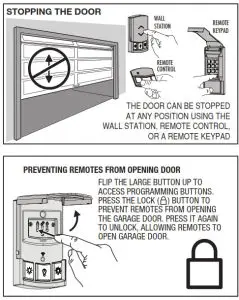
Vacation Lock for Additional Security
- Pull the large button up to access the wall station’s programming buttons. Press the LOCK button to prevent remote controls from opening the door after the door is completely closed. The remotes can close the door, but not open it. The door can still be opened or closed by using the wall station’s UP/ DOWN ARROW pushbutton.
NOTE: To signal that the vacation switch is locked, the operator’s light and red light will flash five times if a remote is activated in an attempt to open the door. - Press the wall station’s LOCK button again to return the operator to normal operation.
Controlling the Operator’s Light
- The operator’s light can be lit by pushing the wall station’s LIGHT button. The light will remain on until the LIGHT button is pressed again or the operator is cycled.
- If the operator’s light is on, pushing the wall station’s LIGHT button will turn the operator’s light off.
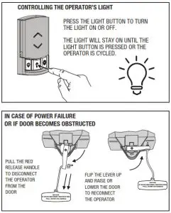
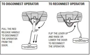
Disconnecting the Door from the Operator
- With the door in any position (preferably closed), carefully pull the red release handle. USE CAUTION IF THE DOOR IS OPEN, THE DOOR MAY DROP.
- The disconnected door can be opened or closed manually.
- To re-connect the operator, flip the release lever up. Raise or lower the door manually until the operator reconnects.
Garage Door Operator Maintenance
Weather conditions may affect the door operation which could require some re-setting of the operator’s adjustments. Doors may swell and become heavier during wet periods, door hinges and rollers might bind during cold periods. To ensure safe operation of the door, perform the following tests, including any additional test steps described.
WARNING
Garage door hardware (springs, cables, brackets, pulleys, etc.) are under extreme pressure and tension. DO NOT ATTEMPT TO LOOSEN, TIGHTEN OR ADJUST ANY DOOR HARDWARE. CALL A QUALIFIED GARAGE DOOR INSTALLATION PROFESSIONAL!
Every Month
- With the door closed, pull the red release handle to disconnect the operator from the door.
- From outside the garage, slowly open the door manually all the way, and then close it all the way. Notice if there is any binding, sticking or rubbing. The door should move smoothly in both directions.
- Raise the garage door about halfway up. Carefully release the door and see if the door balances. It should stay in place. Close the door.
NOTE: If the garage door is unbalanced or the door travel isn’t smooth, have a qualified garage door professional adjust or repair the door. - To reconnect the operator, flip the release lever up and run the operator.
- Perform the Safety Beam Test (Section 12).
- Perform the Safety Reversal System Test as described in Section 15.
WARNING
The garage door operator must not be installed and used on an unbalanced door. The operator’s internal door force sensor will not function properly on an unbalanced door. Risk of serious injury or death may result.
After Servicing the Operator
- Perform the Safety Beam Test (Section 12).
- Perform the Open and Close Limit Adjustments (Section 14).
- Perform the Safety Reversal System Test (Section 16).
Every 6 Months
Check the belt or chain tension.
- For belt-drive rails, examine the length of the tension spring in the traveler. It should be about 1” long.
- For chain-drive rails, examine the spacing between the turnbuckle and the rail. The turnbuckle should be slightly above the rail.
NOTE: Too much or too little chain tension will cause excessive sprocket noise.
WARNING
Always perform the Safety Reversal System Test (see Section 16) after making any adjustments to the operator.
Chain Adjustment
If necessary, use the following steps to adjust the chain.
- Hold the turnbuckle with a flat blade screwdriver and loosen the two locknuts with a 7/16” end wrench.
- Twist the turnbuckle to adjust the chain tension. Adjust the chain until the turnbuckle is sightly above the rail.
- Hold the turnbuckle with a flat blade screwdriver and tighten the two locknuts with a 7/16” end wrench.
Belt Adjustment
The tension spring in the traveler keeps the belt taut. The factory setting for the tension spring length is .9” long. If the tension spring is longer than 1”, adjust the belt.
- Hold the traveler so the adjustment wheel is visible through the large slot.
- Use a flat blade screwdriver to turn the adjustment wheel to compress the tension spring until its length is between .9” and 1” long.
Every Year
Check the door hardware for lubrication needs.
Lubricate door hinges, rollers, and bearings according to the door manufacturer’s recommended procedures.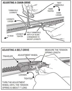
Field Reset
In installations where the door spring, door, or hardware is being replaced, and the operator was already programmed for the old door, reset the operator’s settings using the following steps.
- Press and hold down the UP, DOWN, and LEARN buttons at the same time for ten seconds. The red and green indicators and the operator’s light will flash twice.
- Release the buttons. The operator will reset force settings and erase all set limits, but will still retain all programmed transmitters in memory.
- AFTER PERFORMING A FIELD RESET, BOTH THE OPEN AND CLOSE LIMITS MUST BE ADJUSTED
AND THE AUTOMATIC DOOR FORCE SETUP IS COMPLETED BEFORE THE OPENER WILL FUNCTION.
Troubleshooting
| 1 | Problem | Cause | Remedy |
| 2 | No Problem | Remote control entered into memory | Add any additional remote controls |
| 3 | The door won’t operate | Shorted wall station wires | Check wall station wires. Be sure both are connected to the terminal screws. Check for a staple in the wall station wires. Remove any staples compressing the wire. Check for frayed wires. |
| 4 | The door won’t close | Safety beam obstacle | Check for obstacles. Align the safety beams. |
| 5 | Door reverses or won’t open or close | Open or close force exceeded | Check for obstruction or binding of the garage door. Adjust force factor if necessary. Perform a field reset if necessary. |
| 6 | The door won’t open from remote control | Remote was activated while in vacation mode | Activate vacation mode switch on wall station to exit vacation mode. |
| 7 | Limit error | Down limit and up limit are set too close together | Re-set the open and close limits. If an error occurs again, contact a qualified garage door professional. |
| 8 | Door reverses or won’t open or close | Encoder has detected an error | Check for obstruction or binding of the garage door. If an error occurs again, contact a qualified garage door professional. |
Battery Troubleshooting
These conditions occur when battery backup is installed, and the door is stopped in the open position. Feedback is given via an audible alarm.
| Number of Beeps | Condition | Cause | Remedy |
| 2 | Low Battery | Battery is low | Check that AC power is connected and allow the battery to charge. It will take approximately 10 hours to charge the battery. |
| 3 | No Capacity | The battery is no longer holding a charge. |
Replace the battery now. |
| 4 | Battery Shorted | Battery is internally shorted or battery leads are shorted. |
Check battery wires for shorting. If wires are OK, replace the battery now. |
FCC NOTICE
Changes or modifications not expressly described in this manual or approved by the manufacturer could void the user’s authority to operate the equipment.
This equipment has been tested and found to comply with the limits for a Class B digital device, pursuant to Industry Canada and Part 15 of the FCC Rules. These limits are designed to provide reasonable protection against harmful interference in a residential installation. This equipment generates, uses and can radiate radio frequency energy and, if not installed and used in accordance with the instructions, may cause harmful interference to radio communications. However, there is no guarantee that interference will not occur in a particular installation. If this equipment does cause harmful interference to radio or television reception, which can be determined by turning the equipment off and on, the user is encouraged to try to correct the interference by one or more of the following measures:
- Reorient or relocate the receiving antenna.
- Increase the separation between the equipment and receiver.
- Connect the equipment into an outlet on a circuit different from that to which the receiver is connected.
- Consult the dealer or an experienced radio/TV technician for help.
LIMITED WARRANTY
This product is warranted to the original consumer against defects in material and workmanship for:
| MODEL LDCO 841/863 |
ELECTRONICS 1 year |
MECHANICAL 5 years |
MOTOR Lifetime |
BELT Lifetime |
CHAIN 5 years |
This product is warranted to the original consumer against defects in material and workmanship for the periods mentioned above. The manufacturer will repair, or at its option, replace, any device that it finds requires service under this warranty, and will return the repaired or replaced device to the consumer at the manufacturer’s cost. Devices must be sent to the manufacturer for service at the owner’s expense. This warranty does not apply to damage to the product from negligence, abuse, abnormal usage, misuse, accidents, normal wear or tear or due to failure to follow Seller’s instructions, or arising from improper installation, storage, or maintenance. In no event will the manufacturer be responsible for incidental, compensatory, punitive, consequential, indirect, special or other damages. The remedies provided by this warranty are exclusive. Some states do not allow the exclusion or limitation of incidental and consequential damages, so the above limitation or exclusion may not apply to you. Any warranties implied by law are limited to the time periods set forth above. Some states do not allow limitations on how long an implied warranty lasts, so the above limitation may not apply to you. This warranty gives you specific legal rights, and you may also have other rights which vary from state to state.
For warranty service and shipping instructions contact the manufacturer at the phone number shown below. In order to be protected by this warranty, save your proof of purchase and send a copy with equipment should a repair be required. All products returned for warranty service require a Return Product Authorization Number (RPA# ).
Contact Technical Services at (800) 421-1587 for an RPA# and other important details.
Copyright © 2020 Nortek Security & Control, LLC
10028150 Rev-C