1000W Power Converter
260-9520
OPERATOR’S MANUAL
![]() CAUTION: To Reduce The Risk Of Injury, User Must Read And Understand Operator’s Manual. Save These Instructions For Future Reference.
CAUTION: To Reduce The Risk Of Injury, User Must Read And Understand Operator’s Manual. Save These Instructions For Future Reference.
0099002187-00
SAFETY SYMBOLS
Some of the following symbols may be used on your converter Please study them and learn their meaning. Proper interpretation of these symbols will allow better and safer operation of the converter.
| Symbol | Name | Designation/Explanation |
| V | Volts | Voltage |
| A | Amperes | Current |
| Hz | Hertz | Frequency |
| W | Watts | Power |
| ~ | Alternating current | Type of current |
 |
Direct current | Type or characteristic of current |
 |
Class II construction | Double-insulated construction |
 |
Read the operator’s
manual |
To reduce the risk of injury, read and understand the operator’s manual |
| Warning symbol | Alerts user to warning message | |
 |
Electric shock symbol | Connect only to properly grounded outlets. Replace defective cords or wires immediately. |
SAFETY INFORMATION
The purpose of safety symbols is to attract our attention to possible dangers. The safety symbols, and the explanations with them, deserve your careful attention and understanding. The symbol warnings do not by themselves eliminate any danger. The instructions and warnings they give are no substitutes for proper accident pre- prevention measures.
![]() WARNING Be sure to read and understand all safety instructions in this manual, including all safety alert symbols, such as “DANGER”, “WARNING” and “CAUTION” before using this converter. Failure to follow all instructions listed below may result in electric shock, fire, and/or serious personal injury.
WARNING Be sure to read and understand all safety instructions in this manual, including all safety alert symbols, such as “DANGER”, “WARNING” and “CAUTION” before using this converter. Failure to follow all instructions listed below may result in electric shock, fire, and/or serious personal injury.
SYMBOL MEANING
![]() SAFETY ALERT SYMBOL: Indicates DANGER, WARNING, or CAUTION. May be used in conjunction with other symbols or pictographs.
SAFETY ALERT SYMBOL: Indicates DANGER, WARNING, or CAUTION. May be used in conjunction with other symbols or pictographs.
 DANGER: Failure to obey this safety warning WILL result in death or serious injury to yourself or to others. Always follow safety precautions to reduce the risk of fire, electric shock, and personal injury.
![]() WARNING: Failure to obey this safety warning CAN result in death or serious injury to yourself or to others. Always follow safety precautions to reduce the risk of fire, electric shock, and personal injury.
WARNING: Failure to obey this safety warning CAN result in death or serious injury to yourself or to others. Always follow safety precautions to reduce the risk of fire, electric shock, and personal injury.
![]() CAUTION: Failure to obey this safety warning MAY result in personal injury to yourself or others, or property damage. Always follow safety precautions to reduce the risk of fire, electric shock, and personal injury.
CAUTION: Failure to obey this safety warning MAY result in personal injury to yourself or others, or property damage. Always follow safety precautions to reduce the risk of fire, electric shock, and personal injury.
IMPORTANT SAFETY INSTRUCTIONS
- SAVE THESE INSTRUCTIONS – This manual contains important safety and operating instructions for converter models 260-9520. This manual will show you how to use your converter safely and effectively. Please read, understand and follow these instructions and precautions carefully.
 WARNING:
RISK OF ELECTRIC SHOCK OR FIRE. - WARNING:
People with pacemakers should consult their physician before using the converter. Electromagnetic fields in close proximity to a heart pacemaker may cause pacemaker interference or pacemaker failure. - IMPORTANT: Do not use it in a marine application.
- Keep out of reach of children.
- Do not expose the converter to rain or snow.
- Use of an attachment not recommended or sold by the unit manufacturer may result in a risk of fire, electric shock, or injury to persons.
- Do not disassemble the unit; take it to a qualified serviceman when service or repair is required. Incorrect reassembly may result in a risk of electric shock or fire.
- To reduce risk of electric shock, unplug unit from the outlet before attempting any maintenance or cleaning. Turning off controls will not reduce this risk.
- For the most effective use, place thepower converter on a flat surface.
- Keep the converter well ventilated, in order to properly disperse heat generated while it is used. Make sure there are several inches of clearance around the top and sides and do not block the slots of the converter.
- Do not place the converter in areas such as battery compartments or engine compartments, where fumes or gases may accumulate.
- DO NOT operate the converter if you, the converter, the device being operated or any other surfaces that may come into contact with any power source are wet. Water and many other liquids can conduct electricity, which may lead to serious injury or death.
- Do not place the converter on or near heating vents, radiators or other sources of heat or flammable materials.
- Do not place the converter in direct sunlight. The ideal air temperature for operation is between 50° and 80°F.
- Only connect the power converter to a 12V battery or power supply. Do not attempt to connect the converter to any other power source, including an AC power source. Connecting to a 6V or 16V battery will cause damage to the converter.
- Do not use positive ground electrical systems.
- Make sure the AC plug is tight.
- Do not modify the AC receptacle in any way.
- Do not try extending or otherwise changing the 12V power cord supplied with your converter. Make sure the cord connections are tight.
- Incorrect operation of your converter may result in damage and personal injury.
WARNING:
The converter output is 120V AC and can shock or electrocute the same as any ordinary household AC wall outlet. - Do not use the converter with a product that draws a higher wattage than the converter can provide, as this may cause damage to the converter and product.
- This device does not include an internal Ground Fault Circuit Interrupter (GFCI). For GFCI protection, use a GFCI outlet.
PERSONAL PRECAUTIONS
- Restrictions on Use: This converter may not be used with life support devices or systems. Failure of this converter can reasonably be expected to cause failure of that life support device or system, or to affect the safety or effectiveness of that device or system.
- Wear complete eye protection and protective clothing when working near lead-acid batteries. Always have someone nearby for help.
- Remove all personal metal items from your body, such as rings, bracelets, necklaces, and watches. A lead-acid battery can produce a short circuit current high enough to weld a ring to metal, causing a severe burn.
- Never smoke or allow a spark or flame in the vicinity of the battery or engine.
CONVERTER LOCATION
- Never place the unit directly above the battery; gases from the battery will corrode and damage the converter.
- Never allow battery acid to drip on the unit when reading gravity or filling the battery.
- Do not operate the converter in a closed-in area or restrict ventilation in any way.
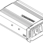
FEATURES
- ON/OFF rocker switch
- LED indicator
Green indicates Power ON.
Red indicates Overload/Interruption in power. - 12 Volt power cord
- 120V standard AC outlets (2)
- USB port – 5V, 2.0A
- High-speed cooling fan
To keep the converter cool, the fan speeds up as the load increases. The fan does not run when the converter is turned off. - Positive Battery Cable Terminal (Red)
- Negative Battery Cable Terminal (Black)
- Ground Terminal and ground wire
Grounds converter, to protect against electrical shock. - Thermal Protection
When the thermal resistor exceeds 80° C (176° F), the converter shuts down until it cools off, and then automatically restarts. - Surge Protection
When the power input from the vehicle’s battery exceeds 16 volts, the converter shuts down. Once the voltage drops down to less than 14 volts, it automatically restarts. - Low-Battery Protection
When the power input from the vehicle’s battery drops to below 10.5 volts, the alarm will sound, the red LED will light, and the converter will shut down.
SPECIFICATIONS
Nominal input voltage ……………………………………………………………12.8-13.2 VDC
Nominal output voltage ………………………………………………………….. 110-125 VAC
Output frequency …………………………………………………………………….60 Hz ± 3 Hz
Operating input voltage …………………………………………………………10.5-15.5 VDC
Continuous output power ………………………………………………………. Up to 1000 W
Surge output power (0.1 seconds) …………………………………………………….. 2000 W
Waveform ……………………………………………………………………..Modified sine wave
Maximum efficiency ……………………………………………………………………………. 90%
Maximum no-load current (at nominal input voltage)………………………. 0.60 ADC
Input overvoltage shutdown ……………………………………………………. 16 ± 0.5 VDC
Input undervoltage alarm …………………………………………………….. 10.5 ± 0.5 VDC
Input low voltage shutdown ……………………………………………………. 10 ± 0.5 VDC
Output power overload shutdown level1 …………………………………… 150 ± 150 W
Internal fuse ………………………………………………………………………………….. 40A x 3
AC receptacles …………………………………………………………..Two, NEMA 5-15 the USA
USB port ………………………………………………………………………………………………. 2A
Battery cables ………………………………………………………………. One black, one red
Ground wire ………………………………………………………………………………. One green
REPLACEMENT PARTS
Battery cable (black) ……………………………………………………………… 3899003407Z
Battery cable (red) ………………………………………………………………… 3899003408Z
BEFORE USING YOUR CONVERTER
Do not use the converter with a product that draws a higher wattage than the converter can provide, as this may cause damage to the converter and product. When you turn on a device or a tool that runs on a motor, the device goes through two stages:
- Start-Up – Requiring an initial surge of power (commonly known as the “starting” or “peak” load).
- Continuous Operation – Power consumption drops (commonly known as the “continuous load”).
The wattage (WATTS) or amperes (AMPS) can normally be found stamped or printed on most devices and equipment, or in the user’s manual. Otherwise, contact the manufacturer to find out whether the device you want to use is compatible with a modified sine wave.
To calculate the wattage:
Wattage = AMPS x 120 (AC Voltage).
To calculate the starting load:
Starting Load = 2 x wattage.
In general, the startup load of the device or power tool determines whether converter has the capability to power it.
To calculate the continuous load:
Continuous Load = AMPS x 120 (AC Voltage).
IMPORTANT: Always run a test to establish whether the converter will operate a particular piece of equipment or device. In the event of a power overload, the converter is designed to automatically shut down.
This safety feature prevents damaging the converter while testing devices and equipment within the wattage range of the converter.
If a device does not operate properly when first connected to the converter, turn the converter ON/OFF switch ON, OFF, and ON again in quick succession. If this procedure s not successful, it is likely that the converter does not have the required capacity to operate the device in question.
IMPORTANT: This converter uses a nonsinusoidal waveform (Fig. 1) which is not the same as power company electricity (Fig 2). Therefore, we do not recommend you use it to power the following devices:
- Switch-mode power supplies
- Linear power supplies
- Class 2 transformers
- Line filter capacitors
- Shaded pole motors
- Fan motors
- Microwave ovens
- Fluorescent and high-intensity lamps (with a ballast)
- Transformer fewer battery chargers
Using the converter with any of these devices may cause the device to run warmer or overheat.
Modified sine waveform produced by converter

Pure sine waveform typical of home AC outlet
IMPORTANT: If you are using the power converter to operate a battery charger, monitor the temperature of the battery charger for about 10 minutes. If the battery charger becomes abnormally warm, disconnect it from the converter immediately.
FASTENING THE CONVERTER TO A FLAT SURFACE
For your convenience, the converter may be fastened horizontally to a flat surface. The area where the converter is to be fastened must be dry, well-ventilated and away from any combustible material or fumes.
- Turn off and disconnect the converter.
- Place the back of the converter with the mounting bracket against a flat, secure surface.
- Attach the converter, using corrosion-resistant screws.
CONNECTING CONVERTER CABLES
The converter and power source must be in the OFF mode.
IMPORTANT: Make sure to connect your converter only to a 12-volt power supply. To avoid electrical shock, it is necessary to ground the converter as well as the device powering it. The converter should be grounded, using a 16 AWG copper wire (included).
NOTE: Do not turn on the converter or the power source until the converter and the power source are grounded.
TO GROUND THE CONVERTER
- Turn off and disconnect the converter.
- Locate the chassis ground screw on the back of the converter.
- Remove the outer hex nut and loosen the second hex nut.
- Attach the grounding wire’s ring connector to the ground terminal of the converter.
- Tighten the hex nut securely. Then, replace the other hex nut and tighten it securely.
- Attach the other end of the wire to a properly grounded location:
Vehicle: Connect to the chassis, unpainted frame part, or engine block of the vehicle.
Fixed location: Connect o a ground rod or other appropriately rated ground.
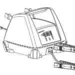
CONNECTING CONVERTER CABLES TO THE CONVERTER
- Locate the Positive and Negative plastic terminals on the right side of the converter and remove the terminal caps completely.
- Install the POSITIVE (RED) cable ring lug onto the POSITIVE (RED) terminal screw. Install the NEGATIVE (BLACK) cable ring lug onto the NEGATIVE (BLACK) terminal screw. Tighten each terminal so that the cable cannot come loose.
CONNECTING THE CONVERTER CABLE TO A 12V BATTERY OR 12V POWER SOURCE:
- Keep hands, hair, clothing, and jewelry clear of battery terminals.
- Wear eye protection and protective clothing.
- For a negative-grounded vehicle (do not use with positive ground electrical systems), connect the POSITIVE (RED) ring terminal from the converter to the POSITIVE (POS, P, +) ungrounded post of the battery. Connect the NEGATIVE (BLACK) ring terminal to the vehicle chassis or engine block away from the battery. Do not connect the terminal to the carburetor, fuel lines, or sheet metal body parts. Connect to a heavy gauge metal part of the frame or engine block.
- To disconnect the converter, remove first the negative terminal and then the positive terminal.
IMPORTANT: Failure to make the correct connections will result in blown fuses and permanent damage to the converter.
BATTERY BANK INSTRUCTIONS
BATTERY BANK ASSEMBLY
![]() WARNING:
WARNING:
READ THESE SAFETY INSTRUCTIONS BEFORE ASSEMBLING THE BATTERY BANK.
- Connect batteries ONLY in parallel (negative terminals together to one cable; positive terminals together to the other cable), as shown in the Battery Bank Example.
- Do not connect 12V batteries in a series with the negative of one battery connected to the positive of the next.
DANGER:
CONNECTING INCORRECTLY MAY RESULT IN VOLTAGE HIGH ENOUGH TO CAUSE ELECTROCUTION.
- While assembling the battery bank, wear splash-resistant ANSI-approved safety goggles and electrically insulated gloves.
- Connect Only similar batteries together in a battery bank. Do not connect old to new, flooded to gel cells, or batteries with different capacities.
- Use extension cables with the specified gauge (or thicker).
6’ or less: 6 AWG; 6-10’: 4 AWG
![]() WARNING:
WARNING:
RISK OF EXPLOSIVE GASES.
• Assemble the battery bank in a clean, well-ventilated location, away from ignition sources and flammable materials.
• To reduce the risk of battery explosion, follow these instructions and those published by the battery manufacturer and manufacturer of any equipment you intend to use in the vicinity f a battery. Review cautionary markings on these products.
CONNECTING THE BATTERIES IN PARALLEL
- First, connect all of the positive terminals to each other.
- Next, connect all of the negative terminals to each other.
- Connect the negative and positive output cables to opposite ends of the bank. Do not allow the output cables to touch one another.
- Test the voltages at the output cables, to make sure that the battery bank is correctly wired.
- If the voltage is higher than 13 volts, part of the battery bank is probably connected in series (a negative terminal of one battery attached to a positive terminal of another) instead of in parallel.
- Carefully examine the diagram and correct the wiring before attaching to the converter.
- Make sure the converter’s switch is set to OFF (O).
- Connect the output cables from the battery bank to the converter.
Fig. 4
Example:
12V/400 Ah † BATTERY BANK
†Bank Capacity = (single battery capacity) x (# of batteries) 400 Ah capacity is for (2) 200 Ah batteries. *200 Ah batteries shown for illustration purposes
OPERATING INSTRUCTIONS
- Connect the converter (see Connecting Converter Cables section.
- Switch the converter’s ON/OFF switch to the ON (I) position.
- The GREEN LED indicator will light, indicating the converter is receiving power.
- Switch the converter’s ON/OFF switch to the OFF (O) position. (The GREEN LED may flash briefly and/or the internal speaker may make a brief “beep”. This is normal.)
- Make sure the device to be operated is turned OFF.
- Plug the device into the converter’s AC outlet.
- Switch the converter’s ON/OFF switch to the ON (I) position.
- Turn the device on.
- To disconnect, reverse the above procedure.
NOTE: If more than one device is to be powered, start one device at a time, to avoid a power surge and overloading the converter. The surge load of each device should not exceed the converter’s Continuous Operation wattage rate.
IMPORTANT: Using the converter with some rechargeable devices may damage the converter and/or device. If you are using the converter to operate a rechargeable device, monitor the temperature of the converter for about 10 minutes. If the converter becomes abnormally hot, disconnect it from the device immediately; do not use the device with the converter.
USING THE CONVERTER TO OPERATE A TV OR AUDIO DEVICE
The converter is shielded and filtered to minimize signal interference. Despite this, some interference may occur with your television picture, especially with weak signals. Below are some suggestions to improve reception.
- Try altering the position of the converter, antenna cables, and television power cord. Add an extension cord from the converter to the TV, to isolate its power cord and antenna cables from the 12 volt power source.
- Try coiling the television power cord and the input cables running from the 12-volt power source to the converter.
- Affix one or several “Ferrite Data LineFilters” to the television power cord. Fer- rite Data Line Filters can be purchased at most electronic supply stores.
- Try grounding the converter with a 16 AWG (minimum) wire, using as short of an extension length as possible.
NOTE: You may hear a “buzzing” sound being emitted from the inexpensive sound systems when operated with the converter. This is due to ineffective filters in the sound system’s power supply. Unfortunately, this problem can only be resolved by purchasing a sound system with a higher quality power supply or higher quality filter.
USING THE USB PORT
The USB port provides up to 2A at 5V DC.
- Plug the device into the USB port.
- Turn the USB device on.
- Reverse these steps when finished using the USB port.
![]() WARNING: The converter draws power, even when the switch is OFF. To avoid battery drain, disconnect the converter when not in use.
WARNING: The converter draws power, even when the switch is OFF. To avoid battery drain, disconnect the converter when not in use.
POWER SOURCE
Your average automobile battery at full charge will provide an ample power supply to the converter when the engine is on. Keep the car running at all times when using the converter. The actual length of time the converter will function depends on the age and condition of the battery and the power demand being placed by the device being operated with the converter.
When possible, recharge your batteries when they are not more than 50% discharged. This gives the batteries a much longer life cycle than recharging when they are ore deeply discharged. The power converter has a battery low voltage shutdown at 10V±0.5V DC. With moderate to heavy loads, this will protect against over-discharging the battery. If the converter is running only light loads it is advisable to recharge before the converter’s low voltage shutdown point is reached.
IMPORTANT: The converter draws low amperage from the battery with the main ON/OFF switch turned on and no load connected. To prevent battery discharge, turn the converter off when you are not using it.
LED INDICATOR AND SHUTDOWN PROTECTION
The Green LED lights automatically when the converter is plugged into a 12 volt DC power source and is turned on. The Red LED lights, the alarm sounds, and the converter automatically turn itself off under the following conditions:
- When the power input from the vehicle’s battery drops to approximately 10.5 volts, the low voltage alarm will sound. When the voltage goes on below 10 VDC, the inverter shuts off. Recharge or replace the battery.
- When the power input from the vehicle’s battery exceeds 16 volts, high voltage overload protection occurs.
- The continuous load demand from the equipment or device being operated exceeds the continuous load rating of the converter. Use a higher capacity converter or lower-rated device.
- The thermal resistor exceeds 80° C (176° F.) Allow the converter to cool. Do not block the cooling slots or airflow over and through the converter. Reduce the load on the converter to the continuous rated output.
RESET: To reset after shutdown occurs, switch the converter’s ON/OFF switch to the OFF (O) position. Check the source of the problem and correct it. Switch the converter’s ON/OFF switch to the ON (I) position.
IF THE CONVERTER’S FUSE BLOWS
Your power converter is fitted with fuses, which should not have to be replaced under normal operating conditions. A blown fuse is usually caused by reverse polarity or a short circuit within the device or equipment being operated.
If a fuse does blow, take the converter to a qualified technician for repair.
MAINTENANCE AND STORAGE INSTRUCTIONS
- Before each use, ensure that all of the converter’s components are in place and in good working condition.
- After use and before performing maintenance, unplug and disconnect the converter.
- Use a clean, dry cloth to wipe the external surfaces of the converter’s case.
- Servicing does not require opening the unit, as there are no user-serviceable parts. All servicing should be performed by qualified service personnel.
- Store inside, in a cool, dry place, out of the reach of children.
- Recycle or properly dispose of internal electrical components.
| PROBLEM | POSSIBLE CAUSE | SOLUTION |
| Low or no output voltage. | Poor contact at terminals. Using the incorrect type of voltmeter to test output voltage. | Disconnect and reconnect the 12V connections. Use a true RMS reading meter. |
| Red LED is lit. | The battery voltage is below 10 volts. The equipment being operated is drawing too much power. The converter is too hot(thermal shutdown | Recharge or replace the battery. Use a higher capacity converter; do not use this equipment. Allow the converter to cool. Check for adequate ventilation. Reduce the load on the converter to the rated continuous power output. |
| The alarm sounds continuous. | Input voltage is below 10.5volts. Poor or weak battery connection. | Recharge or replace the battery. Check for poor connection to the battery. Make sure connection points are clean. |
| The device does not operate properly when first connected to the converter. | The converter may not have the required capacity to operate the device. | Turn the converter switch OFF and ON, reset the converter. |

1000W Power Converter
WARRANTY
90-DAY MONEY-BACK GUARANTEE
This MASTERFORCE™ brand power converter carries our 90-Day Money-Back Guarantee. If you are not completely satisfied with your MASTERFORCE™ brand product for any reason within ninety (90) days from the date of purchase, return the item with your original receipt to any MENARDS ® retail store, and we will provide you a refund – no questions asked.
3-YEAR LIMITED WARRANTY
This MASTERFORCE™ brand power converter carries our famous No-Hassle 3-Year Limited Warranty to the original purchaser. If, during normal use, this ASTERFORCE™ product breaks or fails due to a defect in material or workmanship within three (3) years from the date of original purchase, simply bring the item with the original sales receipt back to your nearest MENARDS ® retail store. At its discretion, MASTERFORCE™ agrees to have the item or any defective part(s) repaired or replaced with the same or similar MASTERFORCE™ product or part free of charge, within the stated warranty period, when returned by the original purchaser with the original sales receipt. Notwithstanding the foregoing, this limited warranty does not cover any damage that has resulted from abuse or misuse of the Merchandise. This warranty: (1) excludes expendable parts including but not limited to blades, brushes, belts, bits, light bulbs, and/or batteries; 2) shall be void if this product is used for commercial and/or
rental purposes; and (3) does not cover any losses, injuries to persons/property or costs. This warranty does give you specific legal rights and you may have other rights, which
vary from state to state. Be careful, converters are dangerous if improperly used or maintained. Seller’s employees are not qualified to advise you on the use of this merchandise. Any oral representation(s) made will not be binding on the seller or its employees. The rights under this limited warranty are to the original purchaser of the merchandise and may not be transferred to any subsequent owner. This limited warranty is in lieu of all warranties, expressed or implied including warranties of merchantability and fitness for a particular purpose. Seller shall not be liable for any special, incidental, or consequential damages. The sole exclusive remedy against the seller will be for the replacement of any defects as provided herein, as long as the seller is willing or able to replace this product or is willing to refund the purchase price as provided above. For insurance purposes, the seller is not allowed to demonstrate any of these products for you.
For questions/comments, technical assistance or repair parts— Please call toll free at: 1-800-621-5485.
SAVE YOUR RECEIPTS THIS WARRANTY IS VOID WITHOUT THEM
NOTES
___________________________________________

© 2020 Menard, Inc., Eau Claire, WI 54703