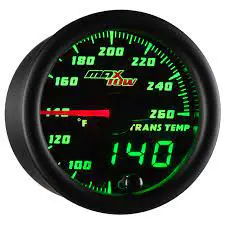
max TOW Transmission Temperature Gauge
The following instructions are for the installation of your Transmission Temperature Gauge. Before you begin, lay out all items and ensure there are no missing parts. If any items are missing, please STOP immediately and contact MaxTow Gauges.
What’s Included
- Transmission Temperature Gauge
- 1/8-27 NPT Transmission Temperature Sensor
- 5ft Power Harness
- 9ft Sensor Harness
- Visor and Mounting Bracket
Wiring Schematic
Red: 12v Constant Source (+)
White: 12v Ignition Switched Source (+)
Orange: 12v Headlight Switched Source (+)
Black: Vehicle/Engine Ground (-)
Warning: Disconnect negative battery terminals before starting any work on the vehicle.
Transmission Temperature Gauge
There are several different ways to connect a Transmission Temperature Gauge to your vehicle. In some cases an adapter is needed to adapt the 1/8-27 NPT Sensor to your transmission. Please take a look at MaxTow.com for available adapters including Thread Adapter, Test Port Extenders and T-Fittings.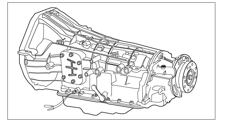
- There are four common types of Transmission Temperature Sensor installations. MaxTow recommends installing the 1/8-27 NPT sensor to a Test Port, Stock Sensor Location, Cooler Line, or Transmission Pan. If the thread size does not match, or if the sensor is too long, a Thread Adapter is required and available at www.MaxTow.com:
- Transmission Test Port: Most vehicle transmissions come equipped with a Test Port Location. This may be located on either the driver or passenger sides of the transmission near the Transmission Oil Pan. The bolt in this port should be removed and the depth of the Test Port should be verified to ensure there is a minimum of 7/8” for the Transmission Temperature Sensor to clear. If there is not enough clearance a Test Port Extender may be used in some applications.
Note: A Test Port Extender is needed on all Dodge Ram trucks with an automatic transmission starting with the 1990 TorqueFlite A518 and 46RH through the 2007 with the 48RE. The 2007.5 with the 68RFE Automatic Transmission and newer trucks require a Cooler Line T-Fitting.A Stubby Temperature Sensor is required for all
4L60e Transmissions. - Stock Sensor Location: Use a T-Fitting (optional) to “T” off your stock sensor location. This will allow you to keep your stock sensor installed, while also allowing you to install an Aftermarket Transmission Temperature Sensor.
- Cooler Line: Most vehicle transmissions have two Cooler Lines. Measure your vehicle’s Cooler Line to determine what size adapter will be required. Common diameters are 5/16”, 3/8”, 1/2”, 5/8” .
- Transmission Pan: Some aftermarket Pans have an available port in order to install a Temperature Sensor. If a port is not available you are able to install a Bulk Head Adapter or you can Weld in a Bung.
Note: Make sure to have a Catch Pan available to catch any lost transmission fluid.
- Transmission Test Port: Most vehicle transmissions come equipped with a Test Port Location. This may be located on either the driver or passenger sides of the transmission near the Transmission Oil Pan. The bolt in this port should be removed and the depth of the Test Port should be verified to ensure there is a minimum of 7/8” for the Transmission Temperature Sensor to clear. If there is not enough clearance a Test Port Extender may be used in some applications.
- To install the Transmission Temperature Sensor, start by applying Teflon tape to the Transmission Temperature Sensor Threads. Install the 1/8th-27 NPT Transmission Temperature Sensor to your vehicle’s transmission system using one of the above methods that will work best for your application, tightening the sensor using a 14mm wrench.
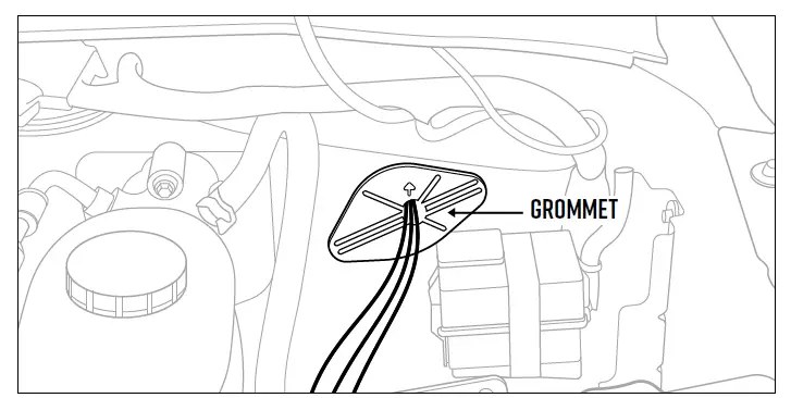
- Plug the Transmission Temperature Sensor Harness into the Transmission Temperature Sensor and route the harness through the engine bay, through the firewall,
using a grommet, keeping it clear of any moving parts, heat sources, and kinks.
Note: Be sure to use a grommet when routing the Harness through the firewall to protect it from being cut or damaged. If one is not available you will need to drill a hole and install a grommet. - Before starting the vehicle be sure to refill the transmission fluid following the manufacturer’s recommended procedures.
Gauge Wiring
- With your Transmission Temperature Sensor Harness connected, plug in the power harness and place the gauge in the mounting location.
- In order to test for power, reconnect the Negative Battery Terminal.
- It may be necessary to remove the Vehicle Trim and/or Kick Panels in order to gain access to the vehicle’s Fuse Box.
- Using a test light, locate a constant 12-volt power source in the vehicle’s fuse panel that receives 12- volt power when the ignition is turned off. You can splice into the circuit or use an optional Expandable Circuit. Connect the Red Wire of the gauge to the Constant 12-volt power source.
Note: It is required to use an automotive grade 18- 20 gauge wire and proper splice connectors when extending any of the power wires. - Repeat the same step for the White Wire of the gauge to locate an Ignition Switched 12-volt power source. This source should not have any power with the key turned off and have 12- volts with the key turned on.
- Connect the Orange Wire of the gauge to the positive Headlight Switch Power Source using a Splice Connector at the headlight switch. You can also use an Expandable Circuit and install into the fuse box if you have a fuse available. This will allow the gauge face to dim 30% when the headlights are turned on.
Note: Make sure that the connection source does not dim. If the voltage is reduced when you lower the Dimmer Wheel it will cause the gauges to flash from not having enough voltage.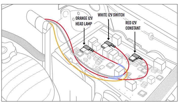
- Locate a clean, reliable grounding source and connect the Black Wire from the gauges.
- After all wiring is complete, turn the vehicle’s key to the “On” position and confirm that your gauges illuminate.
- Turn on the headlights to ensure that the gauges are dimming.
- Start vehicle and check for leaks.
- Reinstall any panels that may have been removed.
- Test drive your vehicle to ensure all gauges are functioning properly.
Selectable Brightness Levels
The Double Vision Gauge Series features 3 selectable brightness settings for both day and nighttime lighting modes. Below are the instructions on how to program each lighting mode.
Daytime Mode
- Press and hold the button located on the gauge face until a “d1” appears in the digital display.
- Press the button again to cycle through the 3 dimming modes.
- Press the button until you have selected your desired setting. Do not touch the button for 5 seconds and the gauge will save your selection.
Nighttime Mode
- This mode is only available if the orange dimmer wire is connected and your headlights are powered.
- Press and hold the button located on the gauge face until an “n1” appears in the digital display.
- Press the button again to cycle through the 3 dimming modes.
- Press the button until you have selected your desired setting. Do not touch the button for 5 seconds and the gauge will save your selection.
Additional Information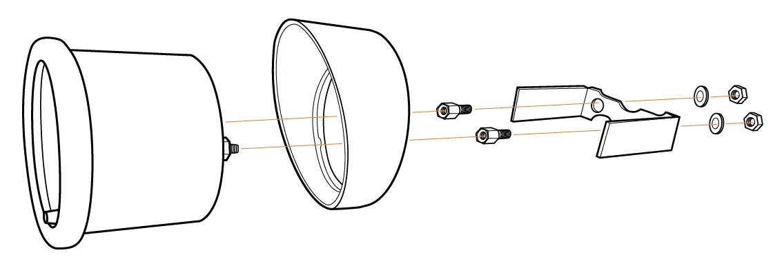
- The supplied optional gauge visor is intended to be placed on the gauge so that the thickest part is at the top, creating a cover over the gauge to help keep sun glare off of the gauge face.
- The included mounting bracket is designed to be used on a flat universal-style mount in order to keep the gauge secure. In some cases one or both legs of the bracket may need to be modified to fit the thickness and contour of the mount.
- Our A-pillar gauge pods do not require the use of the mounting bracket but can be used if you desire, and there is enough space to fit it between the gauge and the gauge pod. When installing the bracket onto the gauge, make sure not to over-tighten as it could pull the rear studs on the back of the gauge and damage it.
- MaxTow Gauges Installation Instructions: Installation documents are solely to provide a guide for individuals that are mechanically and electronically able to install products. If you are unsure about the correct procedure of installation for a product, you should consult a licensed professional.
ONE YEAR NON-TRANSFERABLE LIMITED WARRANTY AND DISCLAIMER
MaxTow Performance, LLC. (“MaxTow”) warrants to the original retail consumer purchaser, and not any other purchaser or subsequent owner, that this Product will be
free from defects in material or workmanship for a period of one (1) year from the purchase date.
For a period of one (1) year from the date of purchase, at no charge to the Purchaser, MaxTow will repair or replace this Product if it is determined by MaxTow to be
defective. After the warranty period, the Purchaser must pay all charges for parts and labor.
Coverage under this warranty is only valid within the United States, including its territories, as well as in certain other countries. Purchasers should check our website,
www.MaxTow.com, to determine the warranty coverage in the countries in which they are located.
MaxTow does not warrant the installation of the Product, which is the sole responsibility of the Purchaser. Installation should be done by licensed professionals.
Improper installation may cause damage to the Product and any vehicle in which it is installed, and may cause burns and electrical injury to individuals. MaxTow’s
warranty does not cover any expenses incurred in removing Products that are defective or re-installing replacement Products in their place.
During the warranty period, to have the Product repaired or replaced, the Purchaser must return the Product, freight prepaid by the Purchaser, to MaxTow (but for
customers in the contiguous United States, MaxTow will pay the shipping charges if any Product fails during the first thirty (30) days after purchase). The Product must
be returned in its original carton or in a similar package affording an equal degree of protection. MaxTow will return the repaired or replaced Product, freight prepaid,
to the Purchaser. MaxTow does not provide Purchasers with temporary replacement units during the warranty period or at any other time.
This limited warranty is non-transferable and will automatically terminate if the original retail consumer purchaser resells the Product or transfers the vehicle in which
the Product is installed. An “original retail consumer purchaser” is a person who originally purchases the Product, or a gift recipient of a new Product that is in its
original packaging and unopened.
This limited warranty is subject to all of the following terms and conditions:
TERMS AND CONDITIONS
- NOTIFICATION OF CLAIMS; WARRANTY SERVICE:
If Purchaser believes that a Product is defective in material or workmanship, written notice with an explanation
of the claim shall be given promptly by Purchaser to MaxTow. All warranty claims must be made within the warranty period, and any Products returned to MaxTow
must be shipped in accordance with MaxTow’s procedures (including use of RMA numbers supplied by MaxTow after notification). The repair or replacement of any
Product or part thereof shall not extend the original warranty period. The specific warranty on the repaired part only (not including gauge sensors) shall be in effect
for a period of ninety (90) days following the repair or replacement of that part, or the remaining period of the Product warranty, whichever is greater. MaxTow does
not provide a warranty on replacement gauge sensors. - EXCLUSIVE REMEDY;
ACCEPTANCE: Purchaser’s exclusive remedy and MaxTow’s sole obligation is to supply (or pay for) all labor necessary to repair any Product
found to be defective within the warranty period and to supply new or rebuilt replacements for defective parts. MaxTow will refund the purchase price for such
Product only if repair or replacement fails to remedy the defect. Purchaser’s failure to make a claim as provided in paragraph 1 above or continued use of the Product
shall constitute an unqualified acceptance of such Product and a waiver by Purchaser of all claims thereto. - EXCEPTIONS TO LIMITED WARRANTY:
MaxTow shall have no obligation to Purchaser with respect to any Product that is subjected to any of the following: abuse, improper use, negligence, accident, modification, failure to follow the operating procedures outlined in the user’s manual, failure to follow the maintenance procedures in the service manual for the Product, attempted repair by non-qualified personnel, operation of the Product outside of the published environmental and electrical parameters, or if the Product’s original identification (trademark, serial number) markings have been defaced, altered, or removed. MaxTow excludes from warranty coverage Products sold AS IS and/or WITH ALL FAULTS. MaxTow also excludes from warranty coverage any consumable items such as fuses and batteries. All software and accompanying documentation furnished with, or as part of the Product is furnished “AS IS” (i.e., without any warranty of any kind), except where
expressly provided otherwise in any documentation or license agreement furnished with the Product. - PROOF OF PURCHASE; REGISTRATION:
The Purchaser’s dated bill of sale must be retained as evidence of the date of purchase and to establish warranty eligibility. Registration of any Product or of this limited warranty is voluntary, and failure to register will not diminish any rights available under this warranty.
DISCLAIMER OF WARRANTY
EXCEPT FOR THE FOREGOING WARRANTIES, MAXTOW HEREBY DISCLAIMS AND EXCLUDES ALL OTHER WARRANTIES, EXPRESS OR IMPLIED, INCLUDING, BUT NOT LIMITED TO ANY IMPLIED WARRANTIES OF MERCHANTABILITY, FITNESS FOR A PARTICULAR PURPOSE, OR ANY WARRANTY WITH REGARD TO ANY CLAIM OF INFRINGEMENT THAT MAY BE PROVIDED IN SECTION 2-312(3) OF THE UNIFORM COMMERCIAL CODE OR IN ANY OTHER STATE STATUTE.
LIMITATION OF LIABILITY
THE LIABILITY OF MAXTOW, IF ANY, AND PURCHASER’S SOLE AND EXCLUSIVE REMEDY FOR DAMAGES FOR ANY CLAIM OF ANY KIND WHATSOEVER, REGARDLESS OF THE LEGAL THEORY AND WHETHER ARISING IN TORT OR CONTRACT, SHALL NOT BE GREATER THAN THE ACTUAL PURCHASE PRICE OF THE PRODUCT FOR WHICH SUCH CLAIM IS MADE. IN NO EVENT SHALL MAXTOW BE LIABLE TO PURCHASER FOR ANY SPECIAL, INDIRECT, INCIDENTAL, OR CONSEQUENTIAL DAMAGES OF ANY KIND INCLUDING, BUT NOT LIMITED TO, COMPENSATION, REIMBURSEMENT OR DAMAGES ON ACCOUNT OF THE LOSS OF PRESENT OR PROSPECTIVE PROFITS OR FOR ANY OTHER REASON WHATSOEVER.
GOVERNING LAW: This non-transferable limited warranty shall be governed by the law of the State of New Jersey, U.S.A., and the United States of America, excluding their conflicts of laws principles. The courts of Camden County, New Jersey, shall have the exclusive jurisdiction over any legal action with respect to this warranty. This limited warranty gives specific legal rights. You may also have other rights that may vary from state to state or from country to country. Some states or countries do not allow the exclusion or limitation of incidental or consequential damages, so the above limitations and exclusions may not apply to you. You are advised to consult applicable state or country laws for a full determination of rights.![]()