METAL MAN Auto Darkening Welding Helmet

SAFETY WARNINGS
Auto-Darkening welding helmets are designed to protect the eye and face from sparks, spatter and harmful radiation under normal welding conditions. Auto-Darkening filter automatically changes from a light state to a dark state when an arc is struck and it returns to the light state when welding stops.
The Auto-Darkening welding helmet comes assembled, But before it can be used, It must be adjusted to tit the user properly. Check battery surfaces and contacts and clean it if necessary. Verify if the battery is in good condition and installed properly. Set up for delay time, sensitivity and shade number for your application.
The helmet should be stored in dry, cool and dark area and remove the battery, when not using It for a long time,
WARNING:
- This Auto-Darkening welding helmet is not suitable for laser welding and oxyacetylene welding I cutting processes.
- Never place this helmet and Auto-Darkening filter on a hot surface.
- Never open or tamper with the Auto-Darkening filter.
- This Auto-Darkening welding helmet will not protect against severe impact hazards.
- This helmet will not protect against explosive devices or corrosive liquids.
- Do not make any modifications to either the filter or helmet, unless specified in this manual. Do not use replacement parts other than those specified in this manual. Unauthorized modifications and replacement parts will void the warranty and expose the operator to the risk of personal injury.
- Should this helmet not darken upon striking an arc, stop welding immediately and contact your supervisor or your dealer.
- Do not immerse the filter in water.
- Do not use any solvents on the filter screen or helmet components.
- Use only at temperatures: -10°c – +55°C (14°F – 131 °F).
- Storing temperature: -20°C – +70°C (- 4°F – 158° F). The helmet should be stored in dry cool and dark area, when not using it for a long lime.
- Protect filter from contact with liquid and dirt.
- Clean the filter surface regularly; do not use strong cleaning solutions. Always keep the sensors and solar cells clean using a clean lint-free tissue.
- Regularly replace the cracked I scratched I pitted front cover lens.
- The materials which may come into contact with the wearer’s skin can cause allergic reactions in some circumstances.
COMMON PROBLEMS AND REMEDIES
Irregular Darkening Dimming
Headband has been set unevenly and there is an uneven distance from the eyes to the filter lens (Reset the headband to reduce the difference to the filter).
Auto-Darkening filter does not darken or flickers
- Front cover lens is soiled or damaged (Change the cover lens).
- Sensors are soiled (Clean the sensors surface).
- Welding current is too low (Reset the sensitivity level to “higher” side).
Slow response
Operating temperature is too low (Do not use at temperatures below -10° C or 14° F).
Poor vision
- Front I inside cover lens and I or the filter is soiled (Change lens).
- There is insufficient ambient light.
- Shade number is incorrectly set (Reset the shade number).
- Check if removing the film on the front cover lens.
Welding helmet slips
Headband is not properly adjusted (Readjust the headband).
WARNING:
The user must stop using the auto-darkening welding helmet immediately if the above-mentioned problems cannot be corrected. Contact the dealer.
INSTRUCTIONS FOR USE
WARNING: Before using the helmet for welding, ensure that you have read and understood the safety instructions
The helmet comes ready assembled but before it can be used it must be adjusted to fit the user properly and set up for delay time, sensitivity and shade level.
ADJUSTING THE FIT OF THE HELMET
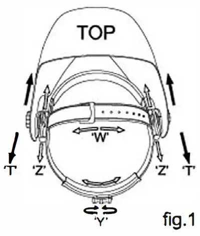
The overall circumference of the headband can be made larger or smaller by rotating the knob on the back of the headband (See adjustment “Y” in fig.1 ). This can be done whilst wearing the helmet and allows just the right tension to be set to keep the helmet firmly on the head without it being too tight.
• If the headband is riding too high or too low on your head, adjust the strap which passes over the top of your head. To do this, release the end of the band by pushing the locking pin out of the hole in the band. Slide the two portions of the band to a greater or lesser width as required and push the locking pin through the nearest hole (See adjustment “W” in fig.1 ).
• Test the fit of the headband by lifting up and closing down the helmet a few times while wearing it. If the headband moves while tilting, re-adjust it until it is stable .
ADJUSTING THE DISTANCE BETWEEN THE HELMET AND THE FACE
Step 1: Undo the block nut (See T in fig.1) to adjust the distance between the helmet and your face in the down position.
Step 2: Loosen the block nut on either side of the helmet and slide it nearer or further from your face. (See adjustment “Z” in fig.1 ). It is important that your eyes are each the same distance from the lens. Otherwise the darkening effect may appear uneven.
Step 3: Re-tighten the block nut when adjustment is complete.
ADJUSTING VIEW ANGLE POSITION
SELECTING SHADE LEVEL
Select the shade level you require according to the welding process you will use by referring to the “Shade Guide Table” below for settings. Turn the shade control knob on the side of the helmet to the shade number required.
SELECTING THE OPERATING MODE
Use the switch button on the back of shade cartridge to select the mode appropriate for the work activity.
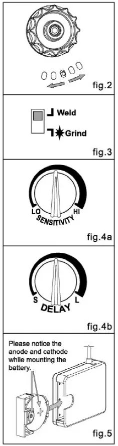
Weld mode – Used for most welding applications. In this mode the shade function is turned on when it optically senses a welding arc. Select shade level, delay time and sensitivity as required (see fig.3).
Grind Mode : Used for metal grinding applications. In this mode, the shade function turned off. The shade is fixed shade DIN 3.5 that allowing a clear view to grind a weld with the helmet providing face protection (see fig.3).
SENSITIVITY
The sensitivity can be set to “high” or “low” by using the infinitely dial knob on the back of the shade cartridge. The “Mid-High” setting is the normal setting for everyday use. The maximum sensitivity level is appropriate for low welding current work, TIG, or special applications. Where the operation of the helmet is disturbed by excess ambient light, or another welding machine close by, use the “low” setting. (See fig.4a). As a simple rule for optimum performance, it is recommended to set sensitivity to the maximum at the beginning and then gradually reduce it, until the filter reacts only to the welding light flash and without annoying spurious triggering due to ambient light conditions (direct sun, intensive artificial light, neighbouring welder’s arcs etc.).
SELECTING DELAY TIME
When welding ceases, the viewing window automatically changes from dark back to light but with a pre-set delay to compensate for any bright afterglow on the workpiece. The delay time I response can be set to “fast” (0.1 sec.) or “slow” (1.0 sec.). As you require using the infinitely dial knob on the back of the shade cartridge. (See fig.4b). It is recommended to use a shorter delay with spot welding applications and a longer delay with applications using higher currents. Longer delays can also be used for low current TIG welding in order to avoid the filter opening when the light path to the sensors is temporarily obstructed by a hand, torch, etc.
BATTERY INSTALLATION
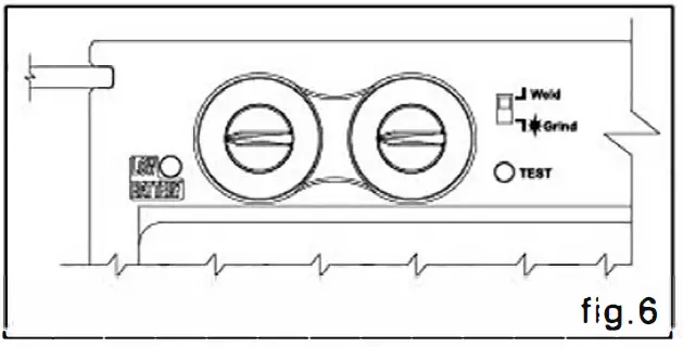
Install batteries into helmet properly, according to fig.6 positive and negative terminal marking on battery ———– jar (See fig.5).
POWER
This ADF cartridge is powered by solar cell and 1 CR2450 lithium battery. Replace batteries when LOW BATTERY light is lit (See fig.5).
TEST
Press and hold test to preview shade selection before welding (See fig.6). When released then viewing window will automatically return to the light state (3.5 Shade).
You are now ready to use the helmet. The shading may be adjusted during use by re-setting the potentiometer control.
SHADE GUIDE TABLE
|
Welding Process |
ARC CURRENT (Amperes) | |||||||||||||
| 0.5
I |
1 I |
I |
5 I |
10
I |
15 I |
20
I |
30 I |
40
I |
60 I |
80 125 175 225
100 150 200 250 I I I I I I I I |
I |
350 450
300 400 I I I I |
500 I |
|
| SMAW | 10 | 11 | 12 | 13 | i 14J |
| CMIG{neiyy) | 12 | 13 | 1;jJ |
MAINTENANCE
REPLACE THE FRONT COVER LENS.
Replace the front cover lens if it is damaged (cracked, scratched, dirty or pitted). Place your finger or thumb into the recess at the bottom edge of the window and flex the window upwards until it releases from one edge (See fig. 7).
REPLACE THE INNER COVER LENS.
If it is damaged (cracked, scratched, dirty or pitted).
CHANGING THE SHADE CARTRIDGE (See figs. Ba & 8b).
INSTALLING NEW CARTRIDGE.
Take the new shade cartridge and pass the potentiometer cable under the wire loop before dropping the cartridge into its retaining frame inside the helmet. Press down the wire loop clip and ensure that the front edge of the loop is properly retained under the retaining lugs as shown in fig. Sb.
Fasten the potentiometer to the inside of the helmet with the shaft protruding through the hole. Push the shade control knob onto the shaft.
CLEANING:
Clean helmet by wiping with a soft cloth. Clean cartridge surfaces regularly. Do not use strong cleaning solutions. Clean sensors and solar cells with methylated spirit and a clean cloth and wipe dry with a lint-free cloth.

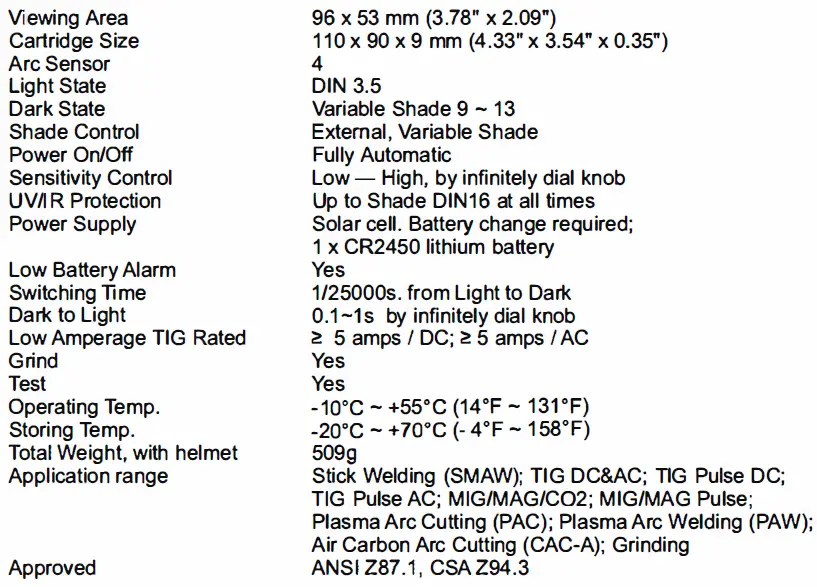
TECHNICAL SPECIFICATIONS
PARTS LIST and ASSEMBL
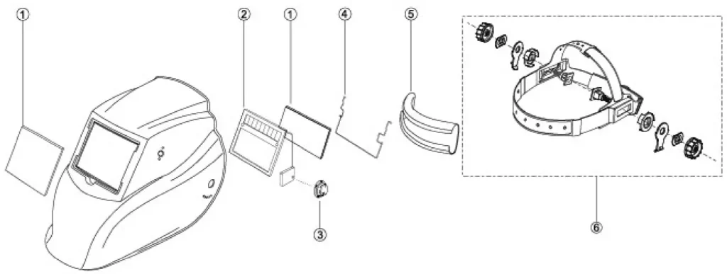
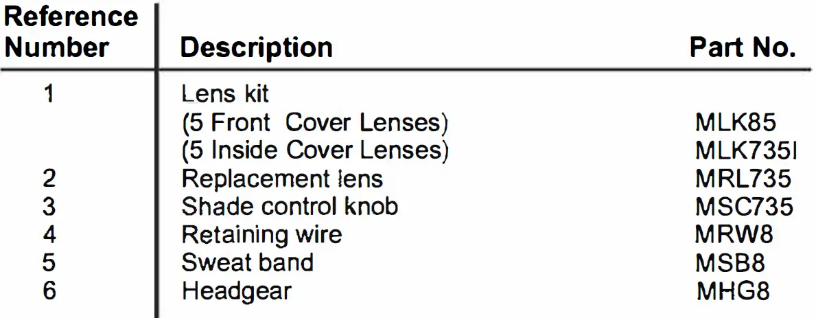
![]()