MIFARE QR Code proximity reader User Manual

-
Introduction
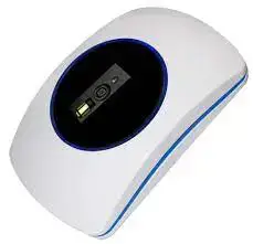
ON-PQ510M0W34 is a proximity reader which reads ISO 14443A contactless card/key tag and QR code then send out some standard data format for connecting to Wiegand input of the access control systems. The users may select the suitable models for connecting to dedicated controller PC for various applications.
- Specification
| RFID frequency | 13.56KHz | |
| Applicable cards | Mifare 14443A S50/S70 | |
|
Reading range |
Card |
Max. 6cm |
| Tag | Max. 2.5cm | |
| QR code | 0~16cm | |
| Output format | Wiegand 34 bits | |
| Power input | 12 VDC | |
|
Standby / Operating current |
128mA±10% @ 12 VDC
140mA±10% @ 12 VDC |
|
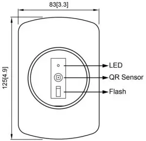
| Flash | Yellow (Power On) | |
| LED | Red (Scanning) | |
| Buzzer | Scanned | |
| Material | ABS | |
| Dimensions(L) ×(W) ×(H) | 125 x 83 x 27mm / 4.9 x 3.3 x 1.1inch | |
| Operating temperature | -10℃~75℃ | |
| Storage temperature | -20℃~85℃ | |
- Installation Guide
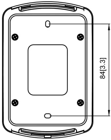
- Drill a 8 mm hole on the wall for passing the cable.
- Drill two 5 mm holes to fix the reader on the wall with provided screws.
- Please make sure to connect wires correctly with the access controller.
- Please use linear (not-switching) type power supply that is isolated from other devices.
- Once you use a separate power supply for the reader, a common ground should be connected between the reader and the controller system.
- For signal transmission, a shielding cable connecting to the controller will reduce the interference from the external environment.
- Dimension: Unit:mm[inch]
![Dimension: Unit:mm[inch]](images/5.webp)

- Wire configuration
| Function | ||
| J1 | ||
| Wire No | Color | Function |
| 1 | Brown | +12V |
| 2 | Red | GND |
| 3 | Orange | DATA0 |
| 4 | Yellow | DATA1 |
| 5 | Green | — |
| 6 | Blue | — |
| 7 | Purple | — |
| 8 | Gray | — |
- Data formats

Wiegand 26 bits output format
| 1 | 2 | 3 | 4 | 5 | 6 | 7 | 8 | 9 | 10 | 11 | 12 | 13 | 14 | 15 | 16 | 17 | 18 | 19 | 20 | 21 | 22 | 23 | 24 | 25 | 26 |
| E | E | E | E | E | E | E | E | E | E | E | E | E | O | O | O | O | O | O | O | O | O | O | O | O | O |
| Summed for even parity(E) | Summed for Odd parity(O) | ||||||||||||||||||||||||
Even parity “E” is generated by summing from bit1 to bit13; Odd parity “O” is generated by summing from bit14 to bit26.
Wiegand 34 bits output format
| 1 | 2 | 3 | 4 | 5 | 6 | 7 | 8 | 9 | 10 | 11 | 12 | 13 | 14 | 15 | 16 | 17 | 18 | 19 | 20 | 21 | 22 | 23 | 24 | 25 | 26 | 27 | 28 | 29 | 30 | 31 | 32 | 33 | 34 |
| C | C | C | C | C | C | C | C | C | C | C | C | C | C | C | C | C | C | C | C | C | C | C | C | C | C | C | C | C | C | C | C | C | C |
| E | E | E | E | E | E | E | E | E | E | E | E | E | E | E | E | E | O | O | O | O | O | O | O | O | O | O | O | O | O | O | O | O | O |
| Summed for even parity(E) | Summed for Odd parity(O) | ||||||||||||||||||||||||||||||||
C= Card number
Even parity “E” is generated by summing from bit1 to bit17; Odd parity “O” is generated by summing from bit18 to bit34.