Mitsubishi Electric Split-Type Air Conditioners
Meanings of symbols displayed on indoor unit and/or outdoor unit

- Since rotating parts and parts which could cause an electric shock are used in this product, be sure to read these “Safety Precautions” before use.
- Since the cautionary items shown here are important for safety, be sure to observe them.
- After reading this manual, keep it together with the installation manual in a handy place for easy reference.
- Be sure to receive a guarantee card from your dealer and check that the purchased date and shop name, etc. are entered correctly.
Marks and their meanings

WARNING :
Incorrect handling could cause serious hazard, such as death, serious injury, etc. with a high probability.

CAUTION :
Incorrect handling could cause serious hazard depending on the conditions.
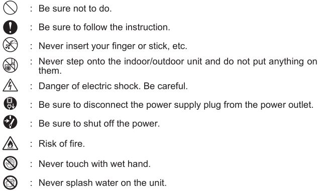
Meanings of symbols used in this manual

WARNING

CAUTION

IMPORTANT
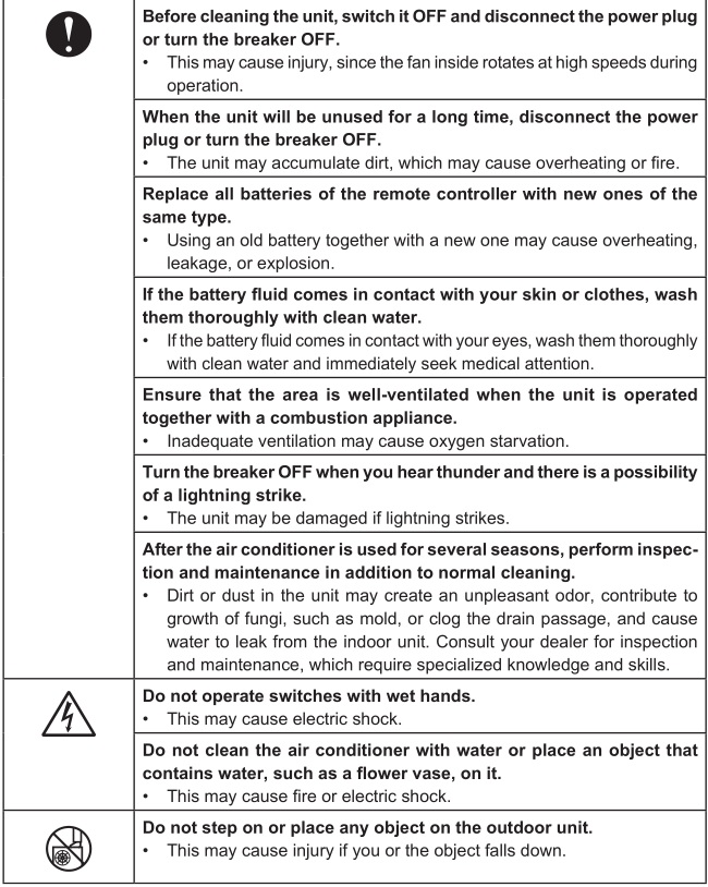
- Dirty filters cause condensation in the air conditioner which will contribute to the growth of fungi such as mold. It is therefore recommended to clean air filters every 2 weeks.
- Before starting the operation, ensure that the horizontal vanes are in the closed position. If operation starts when the horizontal vanes are in the open position, they may not return to the correct position.
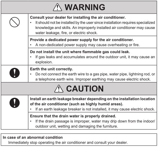
For installation
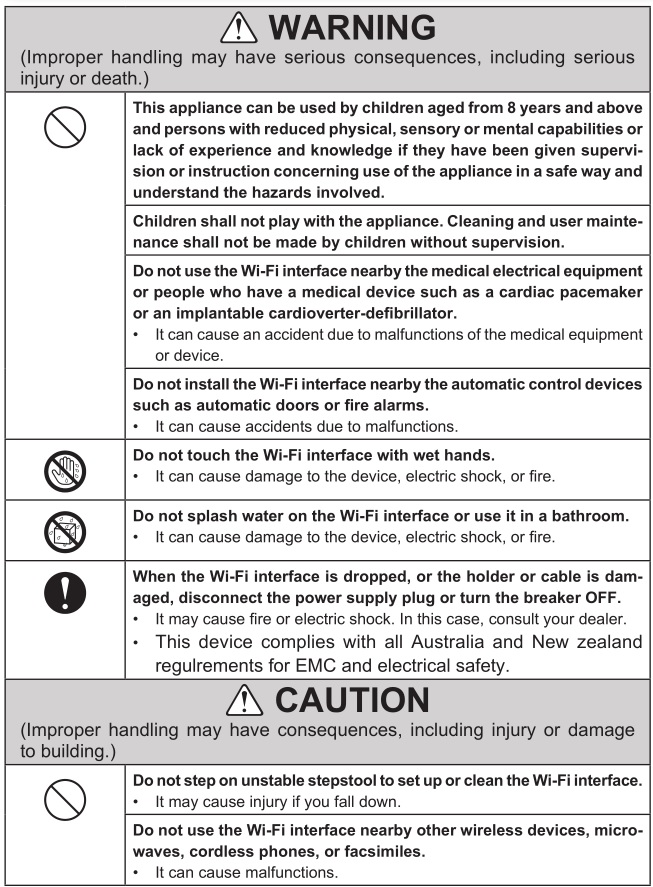
For Wi-Fi interface
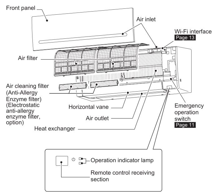
NAME OF EACH PART
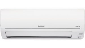
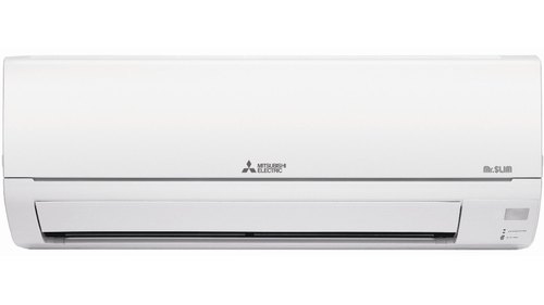
Indoor unit
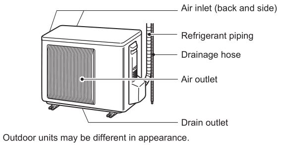
Outdoor unit
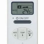
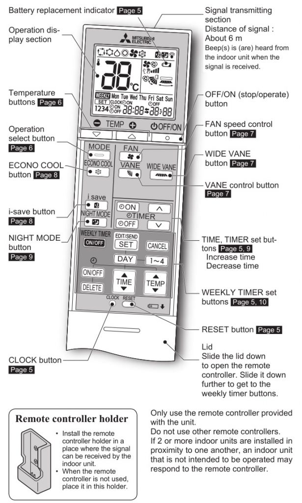
Remote controller
PREPARATION BEFORE OPERATION
Before operation: Insert the power supply plug into the power outlet and/or turn the breaker on.
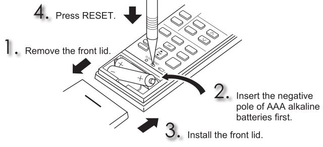
Installing the remote controller batteries
Note:
- Make sure the polarity of the batteries is correct.
- Do not use manganese batteries and leaking batteries. The remote controller could malfunction.
- Do not use rechargeable batteries.
- The battery replacement indicator lights up when the battery is running low. In about 7 days after the indicator starts lights up, the remote controller stops working.
- Replace all batteries with new ones of the same type.
- Batteries can be used for approximately 1 year. However, batteries with expired shelf lives last shorter.
- Press RESET gently using a thin instrument.
If the RESET button is not pressed, the remote controller may not operate correctly.
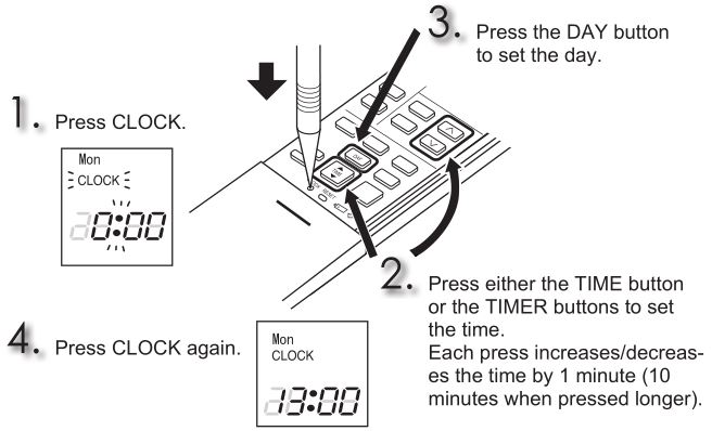
Setting current time
Note:
• Press CLOCK gently using a thin instrument. 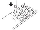
Note: How to set remote controller exclusively for a particular indoor unit
A maximum of 4 indoor units with wireless remote controllers can be used in a room.
To operate the indoor units individually with each remote controller, assign a number to each remote controller according to the number of the indoor unit.
This setting can be set only when all the following conditions are met:
- The remote controller is powered OFF.
- Hold down (1∼4) button on the remote controller for 2 seconds to enter the pairing mode.
- Press (1∼4) button again and assign a number to each remote controller. Each press of (1∼4) button advances the number in the following order: 1 → 2 → 3 → 4.
- Press

After you turn the breaker ON, the remote controller that first sends a signal to an indoor unit will be regarded as the remote controller for the indoor unit. Once they are set, the indoor unit will only receive the signal from the assigned remote controller afterwards.
SELECTING OPERATION MODES
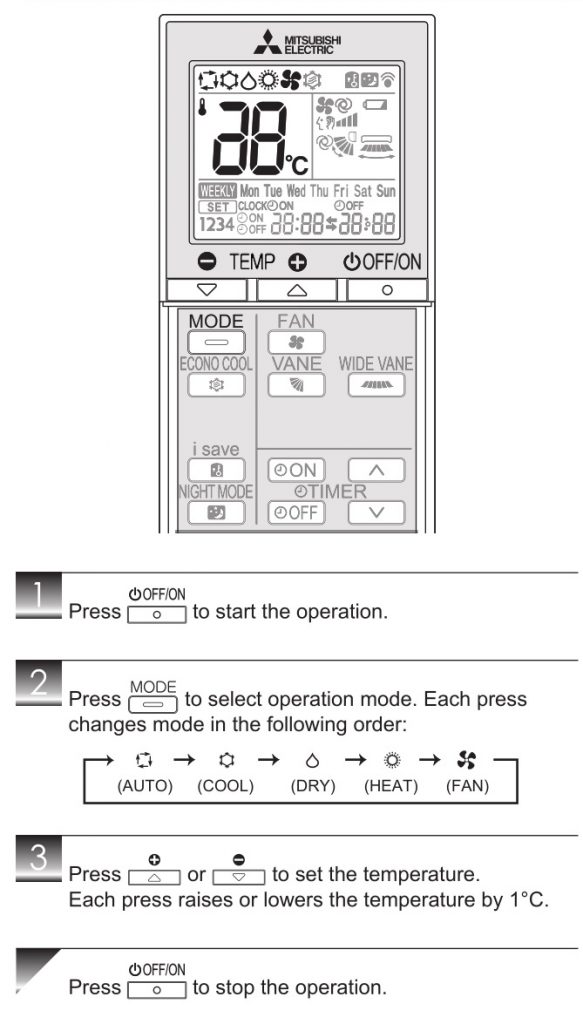
AUTO mode (Auto change over)
The unit selects the operation mode according to the difference between the room temperature and the set temperature. During AUTO mode, the unit changes mode (COOL↔HEAT) when the room temperature is about 2°C away from the set temperature for more than 15 minutes.
Note:
Auto Mode is not recommended if this indoor unit is connected to a MXZ type outdoor unit. When several indoor units are operated simultaneously, the unit may not be able to switch operation mode between COOL and HEAT. In this case, the indoor unit becomes standby mode (Refer to table of Operation indicator lamp).
COOL mode
Enjoy cool air at your desired temperature.
Note:
Do not operate COOL mode at very low outside temperatures (less than -10°C). Water condensed in the unit may drip and wet or damage furniture, etc.
DRY mode
Dehumidify your room. The room may be cooled slightly. Temperature cannot be set during DRY mode.
HEAT mode
Enjoy warm air at your desired temperature.
FAN mode
Circulate the air in your room.
Note:
After COOL/DRY mode operation, it is recommended to operate in the FAN mode to dry inside the indoor unit.
Note:
Multi system operation
Two or more indoor units can be operated by one outdoor unit. When several indoor units are operated simultaneously, cooling/dry/fan and heating operations cannot be done at the same time. When COOL/DRY/FAN is selected with one unit and HEAT with another or vice versa, the unit selected last goes into standby mode.
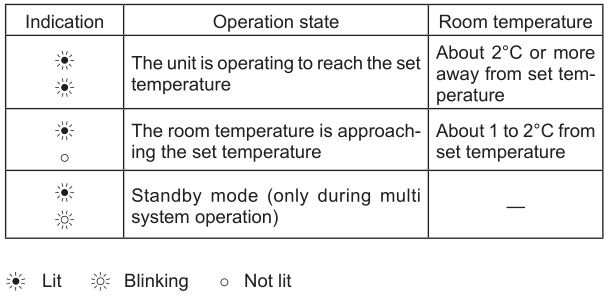
Operation indicator lamp
The operation indicator lamp shows the operation state of the unit.
FAN SPEED AND AIRFLOW DIRECTION ADJUSTMENT
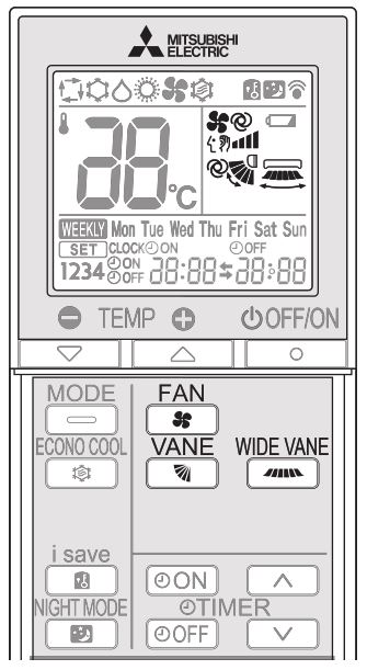
Fan speed
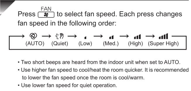
Note:
Multi system operation
When several indoor units are operated simultaneously by one outdoor unit for heating operation, the temperature of the airflow may be low. In this case, it is recommended to set the fan speed to AUTO.
Up-down Airflow direction
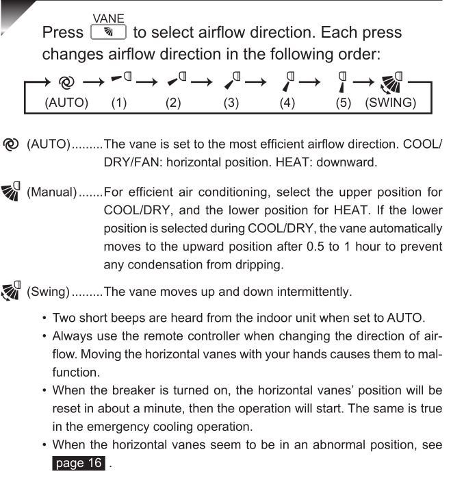
Left-right Airflow direction

I- SAVE OPERATION
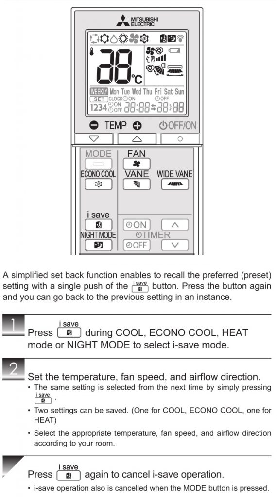
Note:
Example of use:
- Low energy mode
Set the temperature 2°C to 3°C warmer in COOL and cooler in HEAT mode. This setting is suitable for unoccupied room, and while you are sleeping. - Saving frequently used settings
Save your preferred setting for COOL, ECONO COOL, HEAT mode and NIGHT MODE. This enables you to select your preferred setting with a single push of the button.
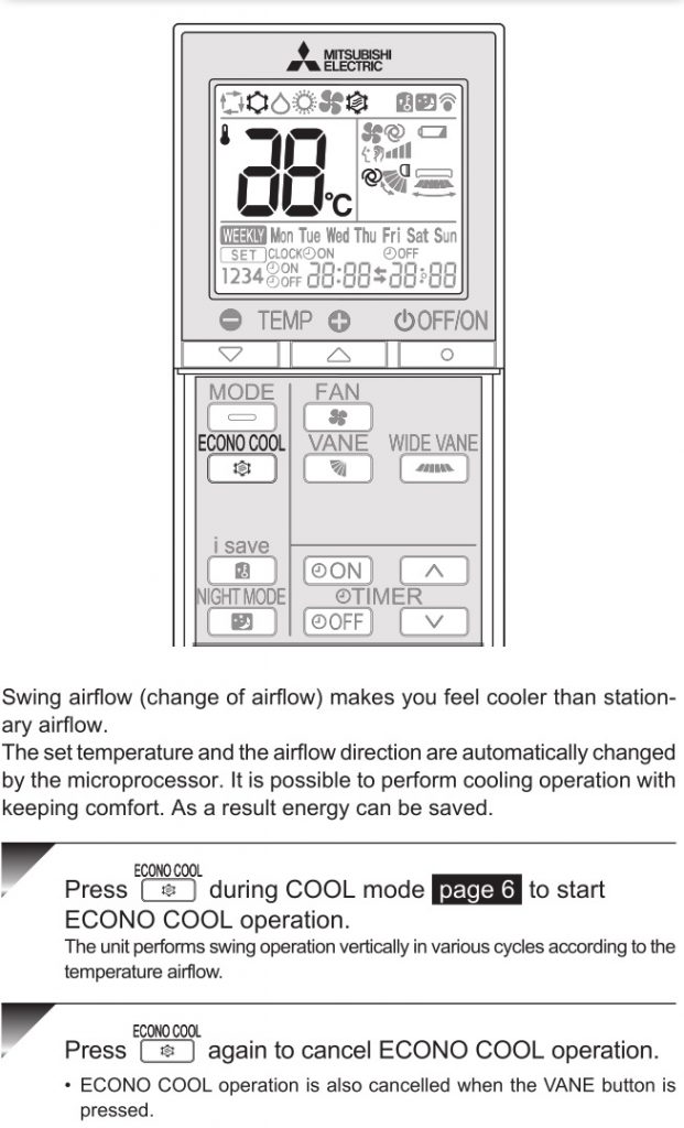
ECONO COOL OPERATION
NIGHT MODE OPERATION
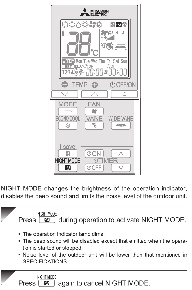
Note:
- The cooling/heating capacity may drop.
- Noise level of the outdoor unit may not change after start-up of the unit, during the protection operation, or depending on other operating conditions.
- The fan speed of the indoor unit will not change.
- The operation indicator lamp will be hard to be seen in a bright room.
- Noise level of the outdoor unit will not decrease during Multi system operation.
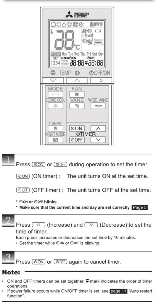
TIMER OPERATION (ON/OFF TIMER)
WEEKLY TIMER OPERATION
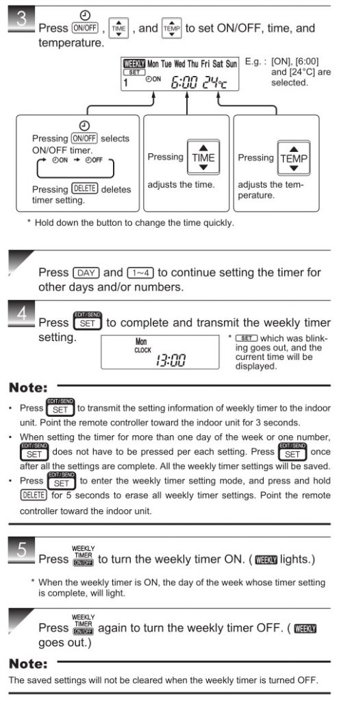
- A maximum of 4 ON or OFF timers can be set for individual days of the week.
- A maximum of 28 ON or OFF timers can be set for a week.
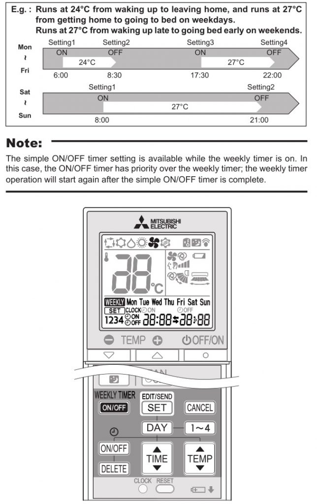
Setting the weekly timer
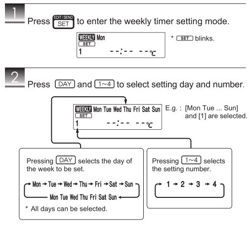
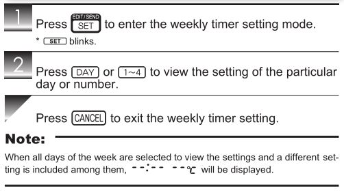
Checking weekly timer setting
DEMAND RESPONSE AND INDOOR UNIT OPERATION (DEMAND TYPE ONLY)
Demand response
This unit has demand response capability which is compliant with AS/NZS 4755.3.1.
To activate this function, you need to make a contract with remote agents such as electric supply company, then this unit should be connected to Demand response enabling devise (DRED). For further information, consult your dealer.
Demand response represents the automated alteration of an electrical product’s normal mode of operation in response to an initiating signal originating from or defined by a remote agent.
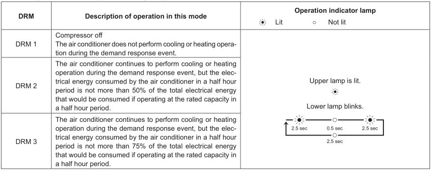
This unit supports 3 Demand Response Modes (DRMs).
Note:
- DRM is automatically activated or released according to the signals from DRED. DRM cannot be invalidated or changed manually.
- You might feel this unit does not sufficiently perform cooling or heating operation during DRM.
- Operation settings can be changed as usual with the remote controller during DRM. However, you might not feel cool or warm enough as DRM is prioritized.
EMERGENCY OPERATION
When the remote controller cannot be used…
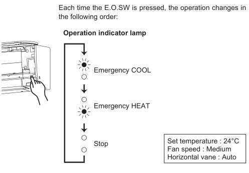
Emergency operation can be activated by pressing the emergency operation switch (E.O.SW) on the indoor unit.
Note:
- The first 30 minutes of operation is test run. Temperature control does not work, and fan speed is set to High.
- In the emergency heating operation, the fan speed gradually rises to blow out warm air.
- In the emergency cooling operation, the horizontal vanes’ position will be reset in about a minute, then the operation will start.
AUTO RESTART FUNCTION
If a power failure occurs or the main power is turned off during operation, “Auto restart function” automatically starts operation in the same mode as the one set with the remote controller just before the shutoff of the main power. When timer is set, timer setting is cancelled and the unit starts operation when power is resumed. If you do not want to use this function, please consult the service representative because the setting of the unit needs to be changed.
CLEANING
Instructions:
- Switch off the power supply or turn off the breaker before cleaning.
- Be careful not to touch the metal parts with your hands.
- Do not use benzine, thinner, polishing powder, or insecticide.
- Use only diluted mild detergents.
- Do not use a scrubbing brush, a hard sponge, or the like.
- Do not soak or rinse the horizontal vane.
- Do not use water hotter than 50°C.
- Do not expose parts to direct sunlight, heat, or fi re to dry.
- Do not apply excessive force on the fan as it may cause cracks or breakage.
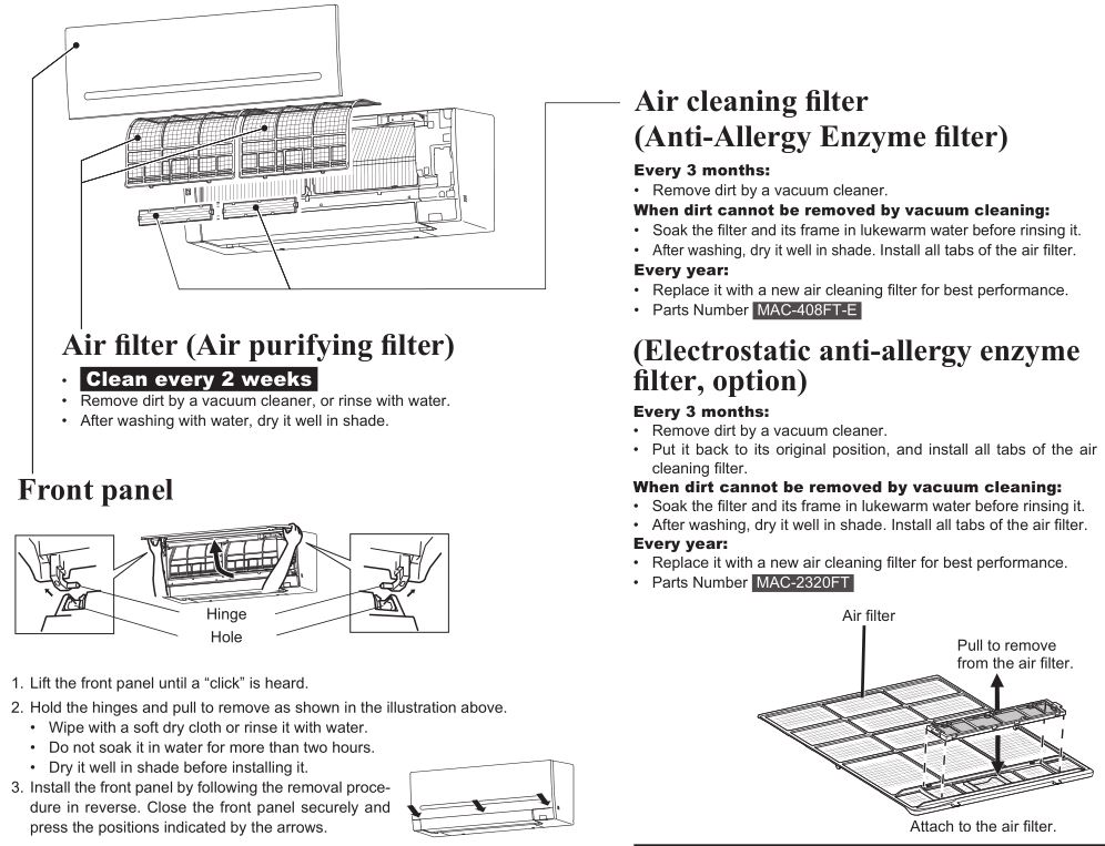

- Clean the filters regularly for best performance and to reduce power consumption.
- Dirty filters cause condensation in the air conditioner which will contribute to the growth of fungi such as mold. It is therefore recommended to clean air filters every 2 weeks.
Wi-Fi INTERFACE SETTING UP (VGK TYPE ONLY)
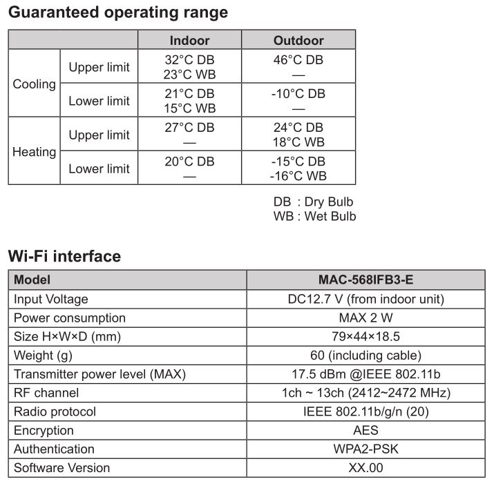
This Wi-Fi interface, communicates the status information and controls the commands from the server by connecting to the indoor unit.

Wi-Fi interface introduction
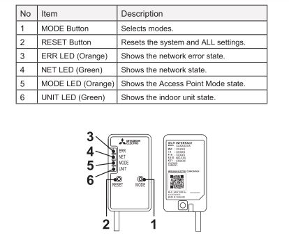
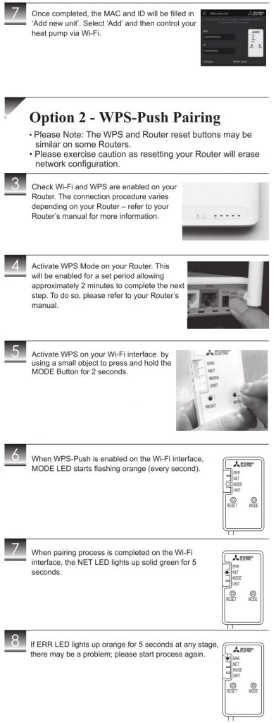
- MODE Button
- WPS-Push
- Hold down the MODE Button for 2 seconds to start WPS-Push Pairing.
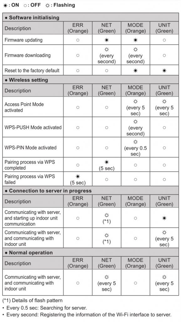
- When WPS-Push is enabled on the Wi-Fi interface, the MODE LED starts flashing orange (every second) and the pairing can be completed by enabling WPS-Push on the Router.
- Access Point Mode
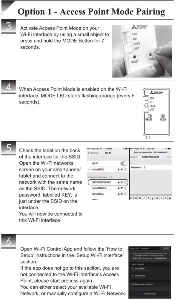
- Hold down the MODE Button for 7 seconds to start Access Point Mode.
- When Access Point Mode is enabled on the Wi-Fi interface, the MODE LED starts flashing orange (every 5 seconds).
- To cancel Access Point Mode, hold down the MODE Button for 7 seconds again and ensure that the MODE LED is no longer flashing.
- WPS-PIN
- Hold down the MODE Button for 15 seconds to start WPS-PIN Pairing.
- When WPS-PIN is enabled on the Wi-Fi interface, MODE LED starts flashing orange (every 0.5 seconds) and the pairing can be completed by enabling WPS-PIN on the Router.
- Before using WPS-PIN, the PIN code of the Wi-Fi interface needs to be set on the Router.
- WPS-Push
- RESET Button
- Hold down the RESET Button for 2 seconds to reboot the system.
- Hold down the RESET Button for 15 seconds to initialize the Wi-Fi interface to the factory default.
Note:
When the Wi-Fi interface is reset to the factory default, ALL the configuration information will be lost. Take great care in implementing this operation.
Information for users
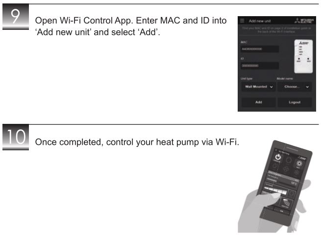
The following steps explain how to connect the Wi-Fi interface to a Router.
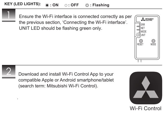
THERE ARE TWO OPTIONS OF CONNECTING
LED Pattern
Wi-Fi INTERFACE SETTING UP (VGK TYPE ONLY)
Troubleshooting
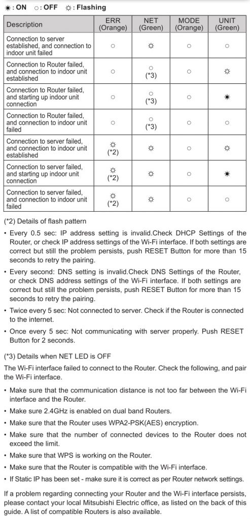
Note:
- Ensure that the Router supports the WPA2-AES encryption setting before starting the Wi-Fi interface setup.
- The End user should read and accept the terms and conditions of the Wi-Fi service before using this Wi-Fi interface.
- To complete connection of this Wi-Fi interface to the Wi-Fi service, the Router may be required.
- This Wi-Fi interface will not commence transmission of any operational data from the system until the End user registers and accepts the terms and conditions of the Wi-Fi service.
- This Wi-Fi interface should not be installed and connected to any Mitsubishi Electric system which is to provide application critical cooling or heating.
- Please write down the information regarding the Wi-Fi interface setting on the last page of this manual, when you set up this Wi-Fi interface.
- At the time of relocation or disposal, reset the Wi-Fi interface to the factory default.
Mitsubishi Electric’s Wi-Fi interface is designed for communication to Mitsubishi Electric’s Wi-Fi service. Third party Wi-Fi interfaces cannot connect to Mitsubishi Electric’s Wi-Fi service. Mitsubishi Electric is not responsible for any (i) underperformance of a system or any product; (ii) system or product fault; or (iii) loss or damage to any system or product; which is caused by or arises from connection to and/or use of any third party Wi-Fi interface or any third party Wi-Fi service with Mitsubishi Electric equipment.
For the latest information regarding Wi-Fi Control:
New Zealand based enquiries please visit: www.mitsubishi-electric.co.nz/wifi
Australian based enquiries please visit: www.mitsubishielectric.com.au/wifi
Mitsubishi Electric Wi-Fi Heat Pump Control
Register Your Heat Pump(s)
Thank you for choosing a Mitsubishi Electric Heat Pump with Wi-Fi Control. Once your Wi-Fi interface is installed, either download the app (search term: Mitsubishi Wi-Fi Control) or visit our website to register your heat pump(s).

Once registered you will be able to control your heat pump with your smartphone, tablet or online account using an internet connection. (For a list of compatible devices, please visit the Mitsubishi Electric website).
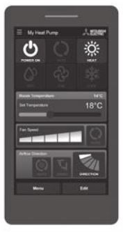
User Manual
A copy of the user manual, terms & conditions and privacy policy can be downloaded at any time from the Mitsubishi Electric website.
Mitsubishi Electric New Zealand
www.mitsubishi-electric.co.nz/wifi
Phone: 0800 639 434
Mitsubishi Electric Australia
www.mitsubishielectric.com.au/wifi
Phone: 1300 728 119
*Apple and the Apple logo are trademarks of Apple Inc., registered in the U.S. and other countries. App Store is a service mark of Apple Inc., registered in the U.S. and other countries.
*Google Play and the Google Play logo are trademarks of Google Inc.
WHEN YOU THINK THAT TROUBLE HAS OCCURRED
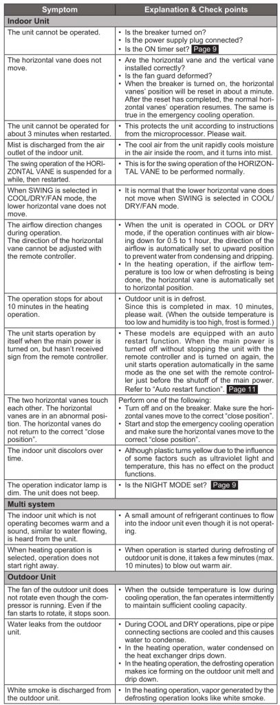
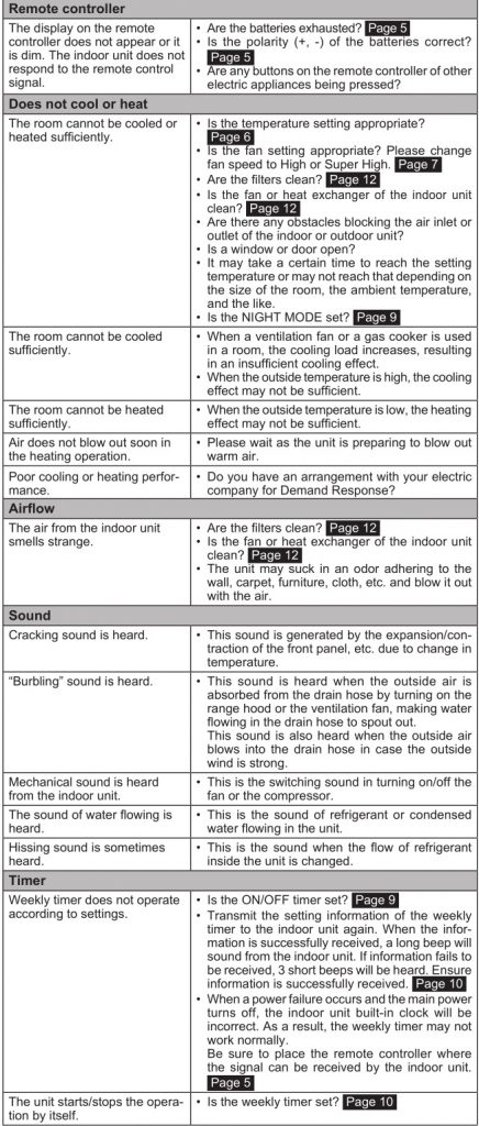
In the following cases, stop using the air conditioner and consult your dealer.
- When water leaks or drips from the indoor unit.
- When the operation indicator lamp blinks.
- When the breaker trips frequently.
- The remote control signal is not received in a room where an electronic ON/OFF type fluorescent lamp (inverter-type fluorescent lamp, etc.) is used.
- Operation of the air conditioner interferes with radio or TV reception. An amplifier may be required for the affected device.
- When an abnormal sound is heard.
- When any refrigerant leakage is found.
WHEN THE AIR CONDITIONER IS NOT GOING TO BE USED FOR A LONG TIME
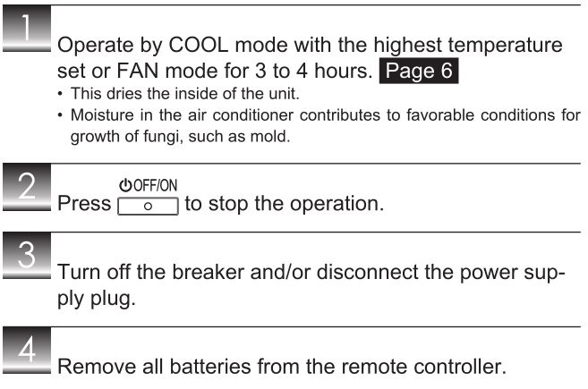
When using the air conditioner again:
INSTALLATION PLACE AND ELECTRICAL WORK
Installation place
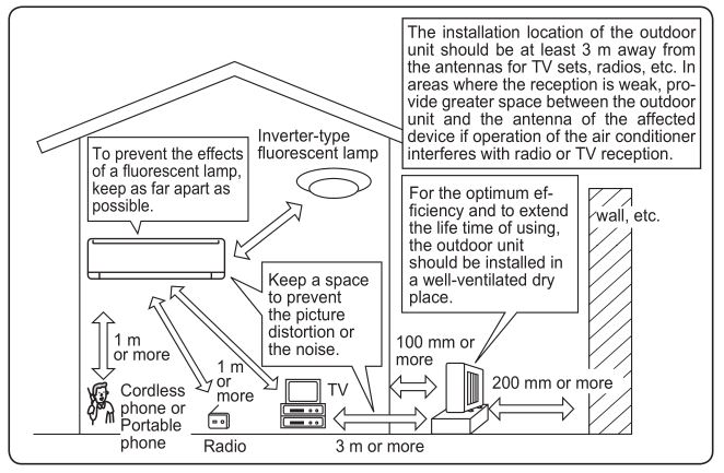
Avoid installing the air conditioner in the following places.
- Where there is much machine oil.
- Salty places such as the seaside.
- Where sulfide gas is generated such as hot spring, sewage, waste water.
- Where oil is splashed or where the area is filled with oily smoke (such as cooking areas and factories, in which the properties of plastic could be changed and damaged).
- Where there is high-frequency or wireless equipment.
- Where the air from the outdoor unit air outlet is blocked.
- Where the operation sound or air from the outdoor unit bothers the house next door.
- The mounting height of indoor unit 1.8 m to 2.3 m is recommended. If it is impossible, please consult your dealer.
- Do not operate the air conditioner during interior construction and finishing work, or while waxing the floor. Before operating the air conditioner, ventilate the room well after such work is performed. Otherwise, it may cause volatile elements to adhere inside the air conditioner, resulting in water leakage or scattering of dew.
Electrical work
- Provide an exclusive circuit for the power supply of the air conditioner.
- Be sure to observe the breaker capacity.
If you have any questions, consult your dealer.
SPECIFICATIONS
FAQS
I’m installing this in new construction. What size electrical wiring and breaker size does it require?
It is a 220v unit. It will run on #12 wire and only requires a 15 amp breaker.
What are the measurements of the blower wall mount unit?
32 3/4 wide by 11 3/4 high measured against the wall. The blower unit is a little larger as it protrudes away from the wall.
Can this be used in a small shed ?
Yes, it will be a great option for a shed. The 9,000 BTU covers an application area of up to 350 sq. ft.
This unit it’s Ac and Heather?
Yes it does both heat and air. Great units
Can this unit be mounted on a pad
I’m not 100% clear on what you mean regarding a pad. If you are talking about the outdoor unit, it can sit on the ground/cement pad or be mounted on a wall. Hopefully that was the question.
Mine has developed and stale unpleasant odor, and we’ve only had it a few months. Does anyone know how to fix this?
I would check that your filters are clean, and that the drain line is not blocked and any condensation can drain from the inside unit. If all else fails, try cleaning the coils if they have gotten dirty
What’s the minimum low ambient temp that they can work for heat??
down to 5° F the system will work at 100% capacity
Is there a Tri-zone version of this Unit? meaning one outdoor Unit to run three wall/indoor units?
This specific one only has outside unit for just this 1 unit. There are others that can run several split units
How many watts?
It’s rated at 6.95 amps at 220 volts. You can look at the manufacturer’s spec sheet on the listing.
Does the indoor unit need clearance at the ceiling and can this be mounted over a window?
yes it needs at least 10 inches from the ceiling and yes over a window if you have the 10 inch clearance
