Modine IHR/OHP/IPT Gas-fired High And Low Intensity Infrared Heaters User Manual
MODEL IHR

MODEL OHP

MODEL IPT
Infrared Heating Defined
Infrared heating systems rely upon the transfer of radiant energy from hot heat exchanger surfaces (up to 1850°F for high intensity heaters) through the air to cooler surfaces, without the use of an air mover. Since radiant energy always travels in a straight line from its source, people and objects within a direct line-of-sight of the heat exchanger become warmed immediately.
While capable of being used for total building heating or large area heating, they are ideally suited for spot heating applications. Spot heating involves small areas such as loading dock doors and single person work cells.
Advantages of Infrared Heating
- No air mover, reducing electricity and maintenance costs while increasing worker comfort from the absence of drafts and annoying fan noise.
- Quick temperature recovery, as only objects need to be heated, not large volumes of air.
- Significant energy savings through use of zone control and/ or spot heating, which heats objects without the need to heat large air volumes.
Typical Applications
The following are examples of applications that can benefit from high-intensity infrared heating:
- Manufacturing facilities
- Vehicle repair centers
- Warehouses and loading docks
- Aircraft hangars
- Indoor tennis courts
- Indoor golf driving ranges
- Emergency vehicle garages
- Indoor stadium seating areas
The following are examples of applications that can benefit from low-intensity infrared heating:
- Manufacturing facilities
- Vehicle repair centers
- Warehouses and loading docks
- Aircraft hangars
- Tennis courts
- Car washes
- Golf driving ranges
- Covered walkways
- Emergency vehicle garages
- Stadium seating areas
- Vestibules
See Infrared Design and Engineering Guide 9-200 for additional application information.
![]()
Do not locate ANY gas-fired unit in areas where chlorinated, halogenated or acid vapors are present in the atmosphere.
![]()
Do not install in potentially explosive or flammable atmosphere laden with dust, sawdust, or similar airborne materials.
As Modine Manufacturing Company has a continuous product improvement program, it reserves the right to change design and specifications without notice.
Modine Breeze® AccuSpec Sizing and Selection Program
The Modine Breeze® AccuSpec is the fastest way to generate performance data based on actual job conditions. The Breeze® AccuSpec program is a web-based sizing and selection program. The program provides a series of step-by-step questions that allow for the easy configuration of Modine products. After a model has been configured, the program can generate Submittal Schedules, Submittal Data (including performance and dimensional drawings), and Specifications.
Fast and Simple Unit/Thermostat/Accessory Selection

Submittal Schedules
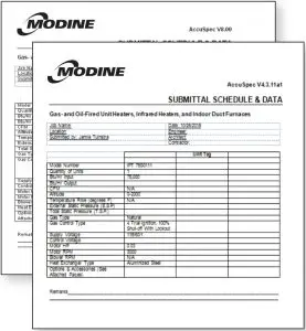
Unit Specific Dimensional Drawings

Job Specific Specifications

For access to the Breeze® AccuSpec program, contact your local Modine sales representative.
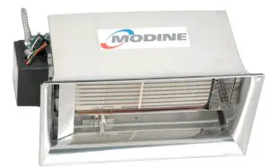
FEATURES AND BENEFITS – MODEL IHR
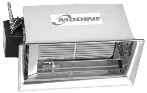
Figure 4.1 – Construction Features – Model IHR
Features
- High temperature cordierite-based grooved ceramic tiles with perforations along both the top and bottom of the grooves
- Polished aluminum reflectors
- 16 gauge aluminized steel frame
- No air mover is utilized
- Input ranges from 30,000 Btu/hr through 160,000 Btu/hr in Natural or Propane gas
- Direct spark or self-energizing standing pilot ignition
- 115V, 25V, or millivolt controls
- Externally-mounted controls
- Burners are replaced by removing one fastener
- CSA design certification for indoor, unvented operation in commercial and industrial installations
Benefits
- Increased temperature and surface area to provide maximum heat transfer while maintaining lower gas input ratings.
- Efficiently direct radiant heat to the desired area, forincreased comfort over wider areas.
- Provides support for simple chain mounting.
- Eliminates fan noise, drafts, maintenance and reduces electrical energy costs.
- Wide input range to accommodate a variety of heating requirements
- Maximize application flexibility.
- Accommodate a wide range of electrical inputs.
- Allow convenient access to gas valve, control system, transformer, and gas orifices, increasing ease of installationand service.
- Eliminates the removal of the unit from its mounted position for service.
- Assures that the unit conforms to national safety standards.
FEATURES AND BENEFITS – MODEL OHP

Figure 5.1 – Construction Features – Model OHP
Features
- ETL Design Certified to ANSI Z83.26 Standard
- Decorative stainless steel windscreen eggcrate grille
- Wind and rain protected design
- 31,000 and 34,000 BTU inputs.
- No Fan Design.
- Externally-mounted controls
- Direct spark or self-energizing standing pilot ignition
- Brushed 430 Stainless Steel Housing
Benefits
- Assures that the unit conforms to national safety standards.
- Prevents wind disturbance.
- Input range to accommodate a variety of heating requirements.
- Flexible fuel type offering.
- Eliminates fan noise, drafts, maintenance and reduces electrical energy costs.
- Allow convenient access to gas valve, control system, transformer, and gas orifices, increasing ease of installation and service.
- Maximize application flexibility.
- Provides maximum corrosion resistance.
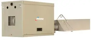
FEATURES AND BENEFITS – MODEL IPT

Figure 6.1 – Construction Features
Features
- Heat-treated darkened aluminized steel tubes
- Polished aluminum reflectors
- Removable side-access panels on both sides of theburner box
- Durable polyester-powder paint
- Permanently-lubricated combustion blower motor
- 180 degree-rotating gas valve
- Sealed burner compartment
- Flame sensor and ignitor mounted externally to thecombustion chamber
- Flame observation window on underside of combustion chamber
- Gas valve operation light on back panel on the unit
- Four-trial separate flame sensor
- System approval for vented and common vented installation
- Weatherproof, water-resistant casing
- ETL design certification
Benefits
- Heat-treated darkening increases both radiant heat output for more heat near the end of the tube system and eliminates the scratching and flaking that can occur with painted tubes. Aluminized steel provides corrosion resistance for longer life.
- Direct radiant heat from the tubes to the desired area, for increased comfort over wider areas.
- Can be removed completely while accessing either side of the unit.
- Maintains life-long new appearance.
- Reduces maintenance.
- Allows convenient access from either side of the burner box.
- Allows manifold pressure adjustments during unit operation, which increases ease of installation and service.
- Improve service access.
- Provides a convenient visual check of unit operation from ground level.
- Indicates that the combustion blower is operating.
- Provides reliable ignition.
- Maximizes installation flexibility.
- Maximizes application flexibility for both indoor and outdoor installation.
- Assures that the unit conforms to national safety standards.
PERFORMANCE AND DIMENSIONAL DATA – MODEL IHR

Table 7.1 – Performance and Dimensional Data
- See Table 8.1 for allowable mounting angles.
- See Figure 7.1.
- Single stage controls are direct spark ignition with 100% safety shutoff and are available as either 115V or 24V
- Millivolt thermostat and 35 feet of wire.

Figure 7.1 – Unit Dimensional Drawing
Model Size: Allowable Mounting Angle Range
30 – 160: 20° – 35°
Table 8.1 – Allowable Mounting Angle Range
Model Sizes: 30: 60: 90: 130: 160
Side of Heater: 30: 32: 48: 48: 50
Back of Heater: 18: 18: 30: 30: 32
Top of Heater: 28: 40: 42: 52: 60
Below Front :72: 72➀: 98: 120: 132
Table 8.2 – Clearances to Combustible Materials (See Figure 8.3)
➀ Clearance is 80 in. when heater is fitted with a parabolic reflector.
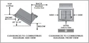
Figure 8.3 – Clearances to Combustibles (See Table 8.2)
PERFORMANCE AND DIMENSIONAL DATA – MODEL OHP
Model: Housing: BTU/Hr input: Ship Weight: Recommended Mounting Heights ➀: Approx. Area Heated: Control Voltage
OHP: 31: 430: SS: 31,000: 59 lbs: 8.0′ to 12.0′: 8′ x 8′: 24 vac
OHP: 34: 430: SS: 34,000: 59 lbs: 8.5′ to 13.0′: 9′ x 9′: 24 vac
Table 9.1 – Performance and Dimensional Data
➀ Clearance is 80 in. when heater is fitted with a parabolic reflector.

Figure 9.1 – Unit Dimensional Drawing

Table 9.2 – Clearances to Combustible Materials
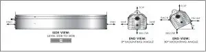
Figure 9.2 – Clearance to Combustibales
PERFORMANCE, UTILITIES AND CLEARANCE – MODEL IPT
 Table 10.1 – Performance
- Recommended Mounting Height and Tube System Applications are meant as a general guide and are adjusted to meet the requirements of the actual application.
The applications are as follows:
— Spot or Area Heating is an application where occupant comfort is the goal and occupant(s) are either relatively stationary (Spot – Example: small work cell or dispersed over a slightly wilder range than with Spot Heating (Area – Example: assembly line). Mounting height is typically at the low end of the range shown above.
— Total Building Heating is an application where average space temperature is to be maintained, however due to the significant temperature gradient differences on long straight tube systems, areas may exist where direct occupant comfort is not achieved. - IPT 100 not available for Propane Gas operation at 50 ft. tube system length.
- IPT 75 not available for Propane Gas operation at 40 ft. tube section length.
Electrical Rating: Gas Connection (inch): Minimum Gas Inlet Pressure (” W.C.):Maximum Gas Inlet Pressure (“W.C.): Manifold Gas Pressure (‘ W.C.): Tube/Vent Diameter (inch)
60Hz/1Ph: 1/2 NPT: 7.0 (natural gas) 11.0 (propane gas): 14.0:
3.5 (natural gas-single stage)
2.5 (natural gas-two stage)
10.0 (propane gas-single stage)
6.2 (propane gas-two stage): 4 (O.D.)
Table 10.2 – Utilities
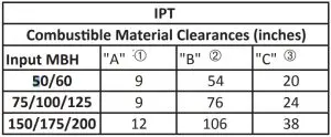
Table 10.3 – Combustible Material Clearances ➀ ➁ ➂
- Clearance to each end and above the U-Tube is 12 inches.
- In unvented applications, clearance from radiant tube end is 36″ in all directions.
- Refer to Figures 8.1 through 8.3.

Figure 10.2 – Stacking Height

Figure 10.1 – Combustible Material Clearances – Straight Tube
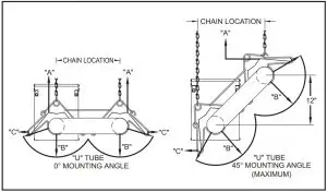
Figure 8.3 – Combustible Material Clearances – U-Tube
DIMENSIONAL DATA – MODEL IPT

Figure 11.1 – Casing Dimensions
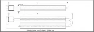
Figure 11.2 – Burner and Tube System Dimensions
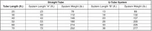
Table 11.1 – Tube Systems Data
Model: Shipping Wt. (lb.)
All Burners: 43
Table 11.2 – Burner Shipping Weights
SPECIFICATIONS, MODEL NOMENCLATURE – MODEL IHR
General
The heater reflector housing shall be constructed of one-side bright polished aluminum. The emitter shall be composed of a perforated ceramic tile on which combustion takes place on the surface. The burner plenum shall be constructed of aluminized steel of one-piece drawn construction. The heater shall be of a modular design employing multiple burners to achieve the specified input.
- The venturi is constructed of stainless or aluminized steel.
- The secondary re-radiating rods shall be constructed of high temperature stainless steel alloy placed in close proximity of the ceramic burner face.
- Parabolic reflectors shall be used when units are installed in high mounting applications or when focusing of the infrared heating pattern is desirable.
- Protective screens shall be used in facilities where debris may damage the heater.
Burner
The ceramic burner face shall operate at a temperature range of 1660 degrees F to 1810 degrees F and shall incorporate asecondary re-radiating surface of stainless steel rods to obtain optimum operating temperature and radiant output.
Reflectors
The heater reflector housing shall be constructed of one-side bright polished aluminum. The emitter shall be composed of a perforated ceramic tile on which combustion takes place on the surface. The burner plenum shall be constructed of aluminized steel of one-piece drawn construction. The heater shall be of a modular design employing multiple burners to achieve the specified input.
- The venturi is constructed of stainless or aluminized steel.
- The secondary re-radiating rods shall be constructed of high temperature stainless steel alloy placed in close proximity of the ceramic burner face.
- Parabolic reflectors shall be used when units are installed in high mounting applications or when focusing of the infrared heating pattern is desirable.
- Protective screens shall be used in facilities where debris may damage the heater.
Controls
Heater(s) shall be equipped with (check one):
- Heaters shall be equipped with one of the following control systems:
Standing Manual Pilot System with 100% safety shut-off of pilot and main burner in case of pilot outage, operating with no external electrical connection but on milli-voltage generated by the pilot flame (NMV-2 or PMV-2).
Direct Spark Ignition System with direct spark ignition of the main burner through a solid state ignition module operating a spark electrode. Loss of power causes 100% safety shut-off of main burner(s). System operates on 120 or 24 volts (NFS-2 or PFS-2). 24V/60Hz/1ph with 6VA maximum power consumption.
Controls shall be exterior mounted for easy accessibility.
All controls shall be rated for a maximum inlet pressure of 1/2 PSI gas pressure. Controls shall be designed for Natural gas having a specific gravity of 0.60, a Btu content of 1050 Btu/ft3 (Alternate: Propane gas having a specific gravity of 1.53, a Btu content of 2500 Btu/ft3) at 0-2000 feet elevation.
Accessories
The following field installed accessories shall be included (check those that apply):
- Chain mounting set – 5’ chain set with 4 “S” hooks. Preset mounting angle of 30°.
- Horizontal parabolic reflector – Directs rays directly downward. Can be used for matching horizontal mounting specifications.
- Full parabolic reflector – Directs rays in a more focused pattern. Typically used in high mounting applications.
- Full parabolic reflector with screen – Directs rays in a more focused pattern. Outer screen protects ceramic grids from objects striking the heater.
- DR heater screen – Screen slips on the outside of the reflectors and protects the ceramic grids.
- Warning plaque – Hung below heater, restates the clearance to combustible warning.
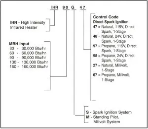
Figure 12.1 – Model Number Designations
SPECIFICATIONS, MODEL NOMENCLATURE – MODEL IPT
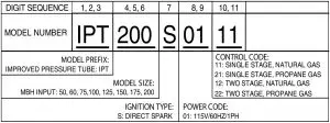
Figure 13.1 – Model Number Designations
General
Contractor shall furnish and install Modine model __________ low intensity infrared heater(s). The low intensity infrared system shall be straight tube________, U-tube_______ configuration. Performance shall be as indicated on the equipment schedule in the plans. The infrared heater(s) shall becertified for indoor and outdoor installations. Infrared heater(s) shall have ETL design certification for use in both the US and Canada.
Casing
The controls, combustion air blower and burner shall be housed in a water-resistant casing, providing weatherproof protection.
The burner and control box casing shall be constructed of not less than 20 gauge aluminized steel. After forming, the casing parts shall be cleaned of all oils and a phosphate coating applied prior to painting. The phosphated parts shall then be finished with an electrostatically applied, gray-green polyester powder paint finish. The applied polyester powder paint shall be baked on to provide an attractive finish on all of the exposed casing parts.
Heat Exchanger
The heat exchanger tubes and combustion chamber shall be constructed of 16 gauge, 4″ O. D. aluminized steel, and the first combustion tube for gas inputs 150,000 Btuh and greater shall be 16 gauge 4″ O. D. 409 Aluminized Stainless Steel. The last heat exchanger tube shall incorporate a turbulator baffle for maximum efficiency of heat transfer.
The heat exchanger tubes must be used in conjunction with reflectors. The reflector can be adjusted from 0° to 45° from the horizontal plane. Reflectors shall be of bright polishe aluminum.
Controls
Input power to the infrared heater(s) shall be 115V/60Hz/1ph. Heater(s) shall be equipped with a direct four-trial (three re-trial), 100% shut-off eletronic ignition control system with a separate flame sensor. Infrared heater(s) shall be equipped with a 115V/25V control transformer. Thermostat shall operate on 25V. Heater(s) will be equipped with a prepurge mode, a differential pressure switch, and an indicator light to prove proper operation of the gas valve. All controls shall be rated for a maximum inlet pressure of 1/2 PSI gas pressure.
Controls shall be designed for natural_______, propane_______ gas having a specific gravity of _______, aBtu content of _______ Btu/ft3 at _______ feet elevation.
Motor
Each heater shall have a single motor. The combustion air blower motor shall be totally enclosed in the control box and the motor shall be protected by a thermal overload switch.
The motor shall be .03 H.P., 115 volt, 60 Hz, single phase, with an operating speed of 3000 rpm.
Products from Modine are designed to provide indoor air-comfort and ventilation solutions for residential, commercial, institutional and industrial applications.
Whatever your heating, ventilating and air conditioning requirements, Modine has the product to satisfy your needs, including:
HVAC
- Unit Heaters:
– Gas
– Hydronic
– Electric
– Oil - Ceiling Cassettes
- Duct Furnaces
- Hydronic Cabinet Unit Heaters, Fin Tube, Convectors
- Infrared Heaters
- Make-up Air Systems
- Unit Ventilators
Ventilation
- Packaged Rooftop Ventilation
School Products
- Vertical Packaged Classroom HVAC:
– DX Cooling/Heat Pump
– Water/Ground Source Heat Pump
– Horizontal/Vertical Unit Ventilators
Specific catalogs are available for each product. Catalogs 75-136 and 75-137 provide details on all Modine HVAC equipment.

Modine Manufacturing Company
1500 DeKoven Avenue
Racine, Wisconsin 53403-2552
Phone: 1.800.828.4328 (HEAT)
www.modinehvac.com
© Modine Manufacturing Company 2021