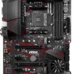
MSI Motherboard
MSI Motherboard
Safety Information
- The components included in this package are prone to damage from electrostatic discharge (ESD). Please adhere to the following instructions to ensure successful computer assembly.
- Ensure that all components are securely connected. Loose connections may cause the computer to not recognize a component or fail to start.
- Hold the motherboard by the edges to avoid touching sensitive components.
- It is recommended to wear an electrostatic discharge (ESD) wrist strap when handling the motherboard to prevent electrostatic damage. If an ESD wrist strap is not available, discharge yourself of static electricity by touching another metal object before handling the motherboard.
- Store the motherboard in an electrostatic shielding container or on an anti-static pad whenever the motherboard is not installed.
- Before turning on the computer, ensure that there are no loose screws or metal components on the motherboard or anywhere within the computer case.
- Do not boot the computer before installation is completed. This could cause permanent damage to the components as well as injury to the user.
- If you need help during any installation step, please consult a certified computer technician.
- Always turn off the power supply and unplug the power cord from the power outlet before installing or removing any computer component.
- Keep this user guide for future reference.
- Keep this motherboard away from humidity.
- Make sure that your electrical outlet provides the same voltage as is indicated on the PSU, before connecting the PSU to the electrical outlet.
- Place the power cord such a way that people can not step on it. Do not place anything over the power cord.
- All cautions and warnings on the motherboard should be noted.
- If any of the following situations arises, get the motherboard checked by service personnel:
- Liquid has penetrated into the computer.
- The motherboard has been exposed to moisture.
- The motherboard does not work well or you can not get it work according to user guide.
- The motherboard has been dropped and damaged.
- The motherboard has obvious sign of breakage.
- Do not leave this motherboard in an environment above 60°C (140°F), it may damage the motherboard.
Specifications
| CPU |
* Please go to intel.com for compatibility information. |
| Chipset | Intel® H510/ B560 chipset |
| Memory |
* Please refer to www.msi.com for more information on compatible memory. |
| Expansion Slots |
|
| Onboard Graphics |
* Available only on processors featuring integrated graphics. |
| Audio | Realtek® ALC897 Codec
|
| LAN | 1x Intel® I219V 1Gbps LAN controller |
| Storage |
* SATA4 will be unavailable when installing M.2 SATA SSD in the M2_1 slot. |
| USB |
|
| Internal Connectors |
|
| Back Panel Connectors |
|
| LED Feature |
|
| I/O Controller | NUVOTON NCT6687D-M Controller Chip |
| Hardware Monitor |
|
| Form Factor |
|
| BIOS Features |
|
| Software |
|
| MSI Center Features |
|
| Special Features |
|
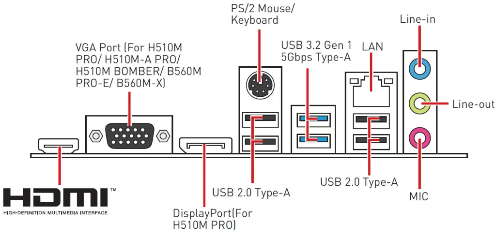
Rear I/O Panel
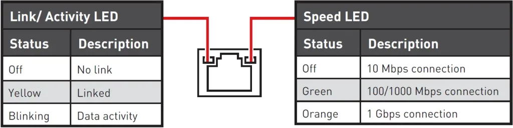
LAN Port LED Status Table
Audio 7.1-channel Configuration
To configure 7.1-channel audio, you have to connect front audio I/O module to JAUD1 connector and follow the below steps.
- Click on the Realtek HD Audio Manager > Advanced Settings to open the dialog below.
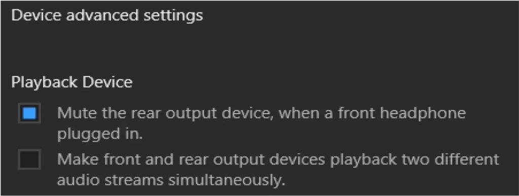
- Select Mute the rear output device, when a front headphone plugged in.
- Plug your speakers to audio jacks on rear and front I/O panel. When you plug into a device at an audio jack, a dialogue window will pop up asking you which device is current connected.
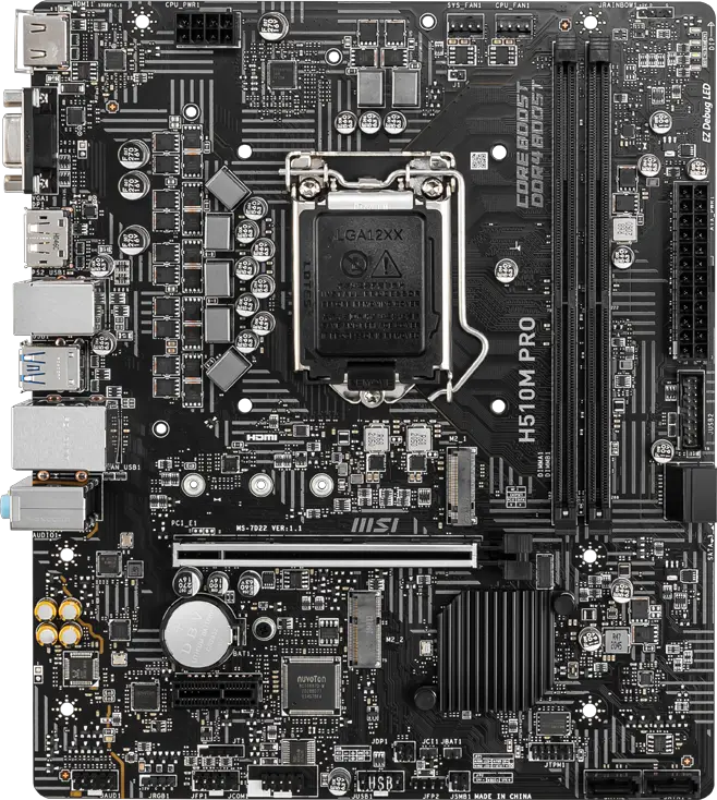
Overview of Components
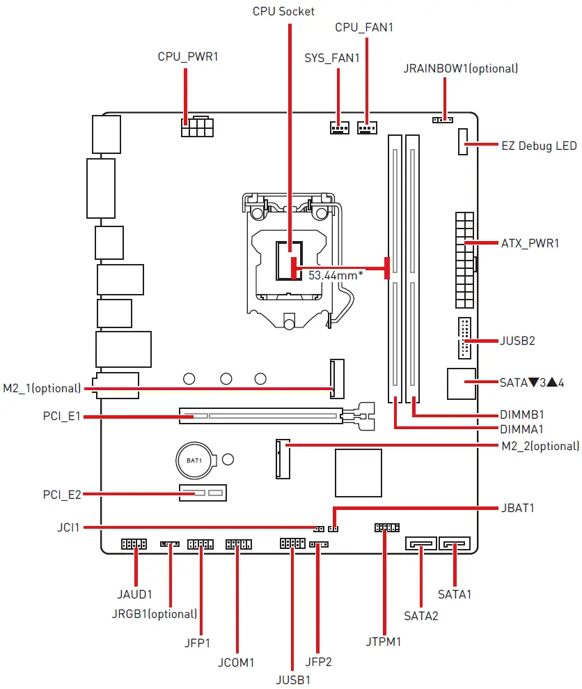
* Distance from the center of the CPU to the nearest DIMM slot.
CPU Socket
Please install the CPU into the CPU socket as shown below.
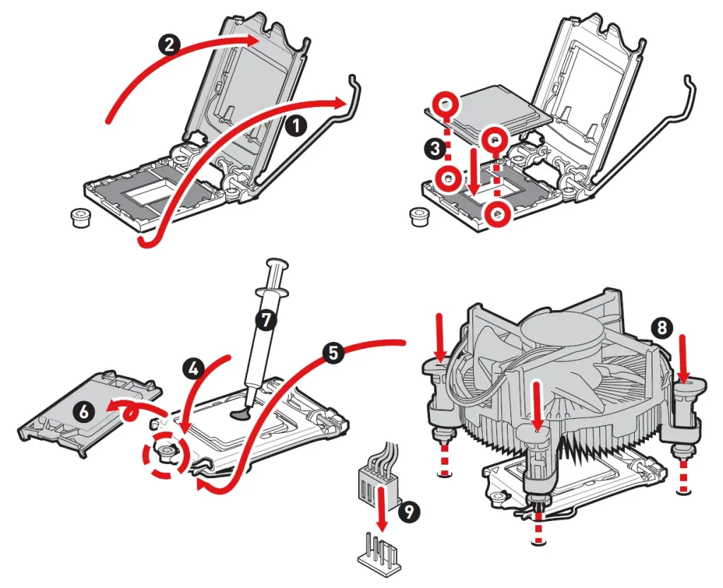
Important
- Always unplug the power cord from the power outlet before installing or removing the CPU.
- Please retain the CPU protective cap after installing the processor. MSI will deal with Return Merchandise Authorization (RMA) requests if only the motherboard comes with the protective cap on the CPU socket.
- When installing a CPU, always remember to install a CPU heatsink. A CPU heatsink is necessary to prevent overheating and maintain system stability.
- Confirm that the CPU heatsink has formed a tight seal with the CPU before booting your system.
- Overheating can seriously damage the CPU and motherboard. Always make sure the cooling fans work properly to protect the CPU from overheating. Be sure to apply an even layer of thermal paste (or thermal tape) between the CPU and the heatsink to enhance heat dissipation.
- Whenever the CPU is not installed, always protect the CPU socket pins by covering the socket with the plastic cap.
- If you purchased a separate CPU and heatsink/ cooler, Please refer to the documentation in the heatsink/ cooler package for more details about installation.
DIMM Slots
Please install the memory module into the DIMM slot as shown below.
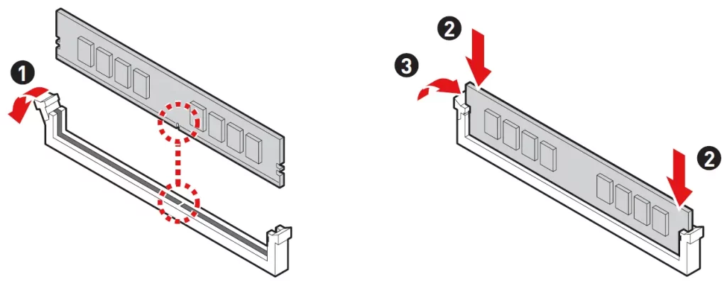
Important
- To ensure system stability for Dual channel mode, memory modules must be of the same type, number and density.
- Some memory modules may operate at a lower frequency than the marked value when overclocking due to the memory frequency operates dependent on its Serial Presence Detect (SPD). Go to BIOS and find the DRAM Frequency to set the memory frequency if you want to operate the memory at the marked or at a higher frequency.
- It is recommended to use a more efficient memory cooling system for full DIMMs installation or overclocking.
- The stability and compatibility of installed memory module depend on installed CPU and devices when overclocking.
- Please refer to www.msi.com for more information on compatible memory.
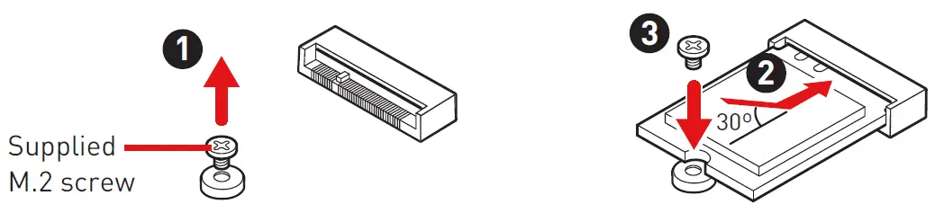
M2_1: M.2 Slot (Key M)
Please install the M.2 device into the M.2_1 slot as shown below.
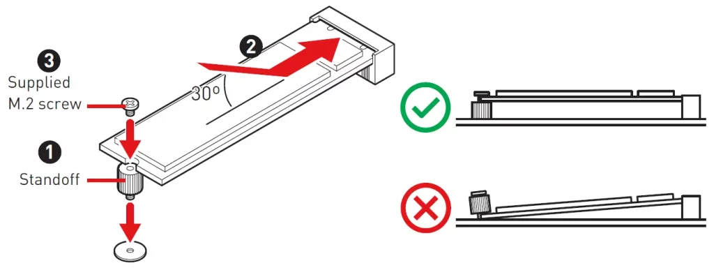
M2_2: M.2 Slot (Key E)
Please install the Wi-Fi module into M.2_2 slot as shown below.
PCI_E1~2: PCIe Expansion Slots
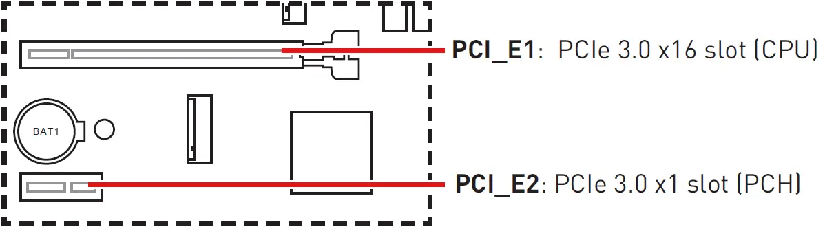
Important
- When adding or removing expansion cards, always turn off the power supply and unplug the power supply power cable from the power outlet. Read the expansion card’s documentation to check for any necessary additional hardware or software changes.
- If you install a large and heavy graphics card, you need to use a tool such as MSI Gaming Series Graphics Card Bolster to support its weight to prevent deformation of the slot.
SATA1~4: SATA 6Gb/s Connectors
These connectors are SATA 6Gb/s interface ports. Each connector can connect to one SATA device.
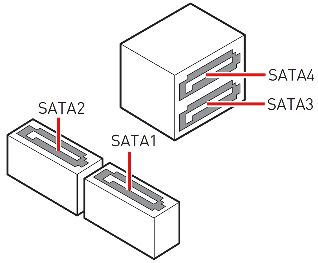
Important
- Please do not fold the SATA cable at a 90-degree angle. Data loss may result during transmission otherwise.
- SATA cables have identical plugs on either sides of the cable. However, it is recommended that the flat connector be connected to the motherboard for space saving purposes.
- SATA1 will be unavailable when installing M.2 SATA SSD in the M2_1 slot.
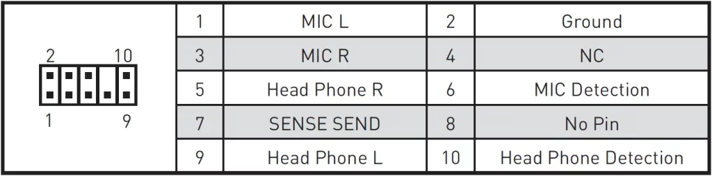
JAUD1: Front Audio Connector
This connector allows you to connect audio jacks on the front panel.
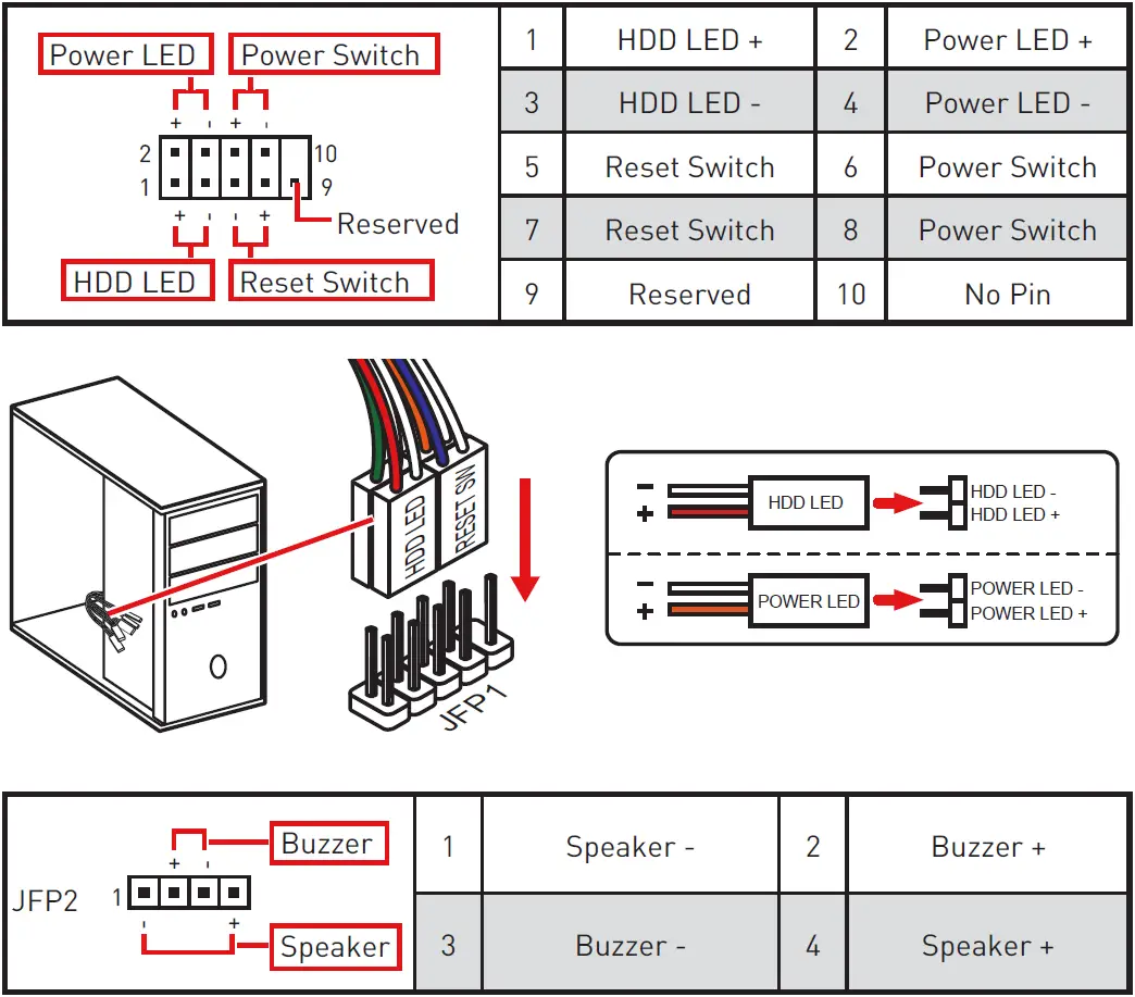
JFP1, JFP2: Front Panel Connectors
These connectors connect to the switches and LEDs on the front panel.
ATX_PWR1, CPU_PWR1: Power Connectors
These connectors allow you to connect an ATX power supply.
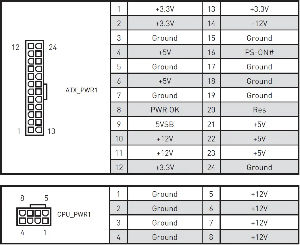
Important
Make sure that all the power cables are securely connected to a proper ATX power supply to ensure stable operation of the motherboard.
JUSB1: USB 2.0 Connector
This connector allows you to connect USB 2.0 ports on the front panel.
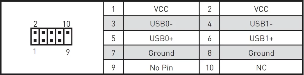
Important
- Note that the VCC and Ground pins must be connected correctly to avoid possible damage.
- In order to recharge your iPad, iPhone and iPod through USB ports, please install MSI® Center utility.
JUSB2: USB 3.2 Gen 1 5Gbps Connector
This connector allows you to connect USB 3.2 Gen 1 5Gbps ports on the front panel.
Important
Note that the Power and Ground pins must be connected correctly to avoid possible damage.
CPU_FAN1, SYS_FAN1: Fan Connectors
PWM Mode fan connectors provide constant 12V output and adjust fan speed with speed control signal. When you plug a 3-pin (Non-PWM) fan to a fan connector in PWM mode, the fan speed will always maintain at 100%, which might create a lot of noise.
| Connector | Default fan mode | Max. current | Max. power |
| CPU_FAN1 | PWM mode | 2A | 24W |
| SYS_FAN1 | DC mode | 1A | 12W |
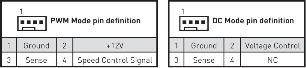
Important
You can adjust fan speed in BIOS > Hardware Monitor.
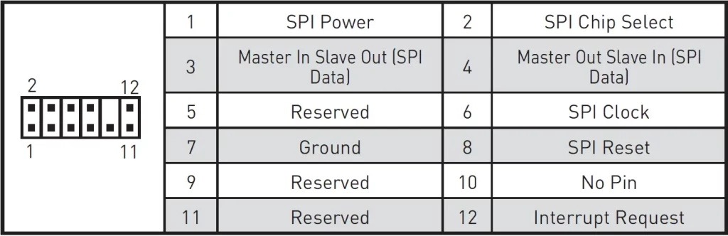
JTPM1: TPM Module Connector
This connector is for TPM (Trusted Platform Module). Please refer to the TPM security platform manual for more details and usages.
JCI1: Chassis Intrusion Connector
This connector allows you to connect the chassis intrusion switch cable.

Using Chassis Intrusion Detector
- Connect the JCI1 connector to the chassis intrusion switch/ sensor on the chassis.
- Close the chassis cover.
- Go to BIOS > Security > Chassis Intrusion Configuration.
- Set Chassis Intrusion to Enabled.
- Press F10 to save and exit and then press the Enter key to select Yes.
- Once the chassis cover is opened again, a warning message will be displayed on screen when the computer is turned on.
Resetting the Chassis Intrusion Warning
- Go to BIOS > Security > Chassis Intrusion Configuration.
- Set Chassis Intrusion to Reset.
- Press F10 to save and exit and then press the Enter key to select Yes.
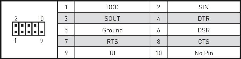
JCOM1: Serial Port Connector
This connector allows you to connect the optional serial port with bracket.
JBAT1: Clear CMOS (Reset BIOS) Jumper
There is CMOS memory onboard that is external powered from a battery located on the motherboard to save system configuration data. If you want to clear the system configuration, set the jumpers to clear the CMOS memory.
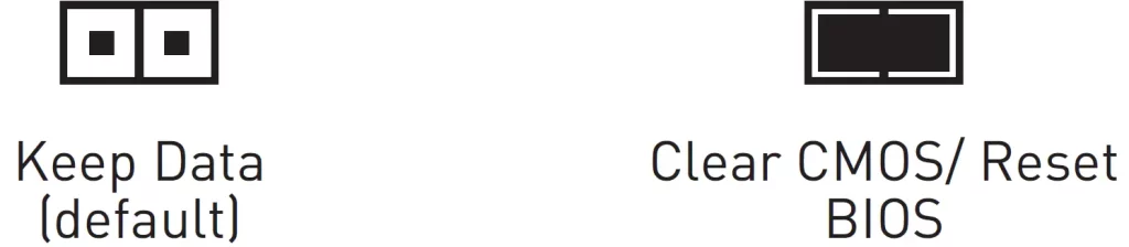
Resetting BIOS to Default Values
- Power off the computer and unplug the power cord.
- Use a jumper cap to short JBAT1 for about 5-10 seconds.
- Remove the jumper cap from JBAT1.
- Plug the power cord and power on the computer.
EZ Debug LED
These LEDs indicate the status of the motherboard.
- CPU – indicates CPU is not detected or fail.
- DRAM – indicates DRAM is not detected or fail.
- VGA – indicates GPU is not detected or fail.
- BOOT – indicates booting device is not detected or fail.
Installing OS, Drivers and MSI Center
Please download and update the latest utilities and drivers at www.msi.com
Installing Windows® 10
- Power on the computer.
- Insert the Windows ® 10 installation disc/USB into your computer.
- Press the Restart button on the computer case.
- Press F11 key during the computer POST (Power-On Self Test) to get into Boot Menu.
- Select the Windows ® 10 installation disc/USB from the Boot Menu.
- Press any key when screen shows Press any key to boot from CD or DVD… message.
- Follow the instructions on the screen to install Windows ® 10.
Installing Drivers
- Start up your computer in Windows® 10.
- Insert MSI® Drive disc into the optical drive.
- Click the Select to choose what happens with this disc pop-up notification, then select Run DVDSetup.exe to open the installer. If you turn off the AutoPlay feature from the Windows Control Panel, you can still manually execute the DVDSetup.exe from the root path of the MSI Drive disc.
- The installer will find and list all necessary drivers in the Drivers/Software tab.
- Click the Install button in the lower-right corner of the window.
- The drivers installation will then be in progress, after it has finished it will prompt you to restart.
- Click OK button to finish.
- Restart your computer.
MSI Center
MSI Center is an application that helps you easily optimize game settings and smoothly use content creation softwares. It also allows you to control and synchronize LED light effects on PCs and other MSI products. With MSI Center, you can customize ideal modes, monitor system performance, and adjust fan speed.
MSI Center User Guide
If you would like to know more information about MSI Center, please refer to http://download.msi.com/manual/mb/MSICENTER.pdf or scan the QR code to access.

Important
Functions may vary depending on the product you have.
UEFI BIOS
MSI UEFI BIOS is compatible with UEFI (Unified Extensible Firmware Interface) architecture. UEFI has many new functions and advantages that traditional BIOS cannot achieve, and it will completely replace BIOS in the future. The MSI UEFI BIOS uses UEFI as the default boot mode to take full advantage of the new chipset’s capabilities.
Important
The term BIOS in this user guide refers to UEFI BIOS unless otherwise noted.
UEFI Advantages
- Fast booting – UEFI can directly boot the operating system and save the BIOS self-test process. And also eliminates the time to switch to CSM mode during POST.
- Supports for hard drive partitions larger than 2 TB.
- Supports more than 4 primary partitions with a GUID Partition Table (GPT).
- Supports unlimited number of partitions.
- Supports full capabilities of new devices – new devices may not provide backward compatibility.
- Supports secure startup – UEFI can check the validity of the operating system to ensure that no malware tampers with the startup process.
Incompatible UEFI Cases
- 32-bit Windows operating system – this motherboard supports only 64-bit Windows 10 operating system.
- Older graphics card – the system will detect your graphics card. When display a warning message There is no GOP (Graphics Output protocol) support detected in this graphics card.
Important
We recommend that you to replace with a GOP/UEFI compatible graphics card or using integrated graphics from CPU for having normal function.
How to check the BIOS mode?
- Power on your computer.
- Press Delete key, when the Press DEL key to enter Setup Menu, F11 to enter Boot Menu message appears on the screen during the boot process.
- After entering the BIOS, you can check the BIOS Mode at the top of the screen.
BIOS Setup
The default settings offer the optimal performance for system stability in normal conditions. You should always keep the default settings to avoid possible system damage or failure booting unless you are familiar with BIOS.
Important
- BIOS items are continuously update for better system performance. Therefore, the description may be slightly different from the latest BIOS and should be for reference only. You could also refer to the HELP information panel for BIOS item description.
- The BIOS screens, options and settings will vary depending on your system.
Entering BIOS Setup
Press Delete key, when the Press DEL key to enter Setup Menu, F11 to enter Boot Menu message appears on the screen during the boot process.
Function key
- F1: General Help
- F2: Add/ Remove a favorite item
- F3: Enter Favorites menu
- F4: Enter CPU Specifications menu
- F5: Enter Memory-Z menu
- F6: Load optimized defaults
- F7: Switch between Advanced mode and EZ mode
- F8: Load Overclocking Profile
- F9: Save Overclocking Profile
- F10: Save Change and Reset*
- F12: Take a screenshot and save it to USB flash drive (FAT/ FAT32 format only).
- Ctrl+F: Enter Search page
* When you press F10, a confirmation window appears and it provides the modification information. Select between Yes or No to confirm your choice.
BIOS User Guide
If you’d like to know more instructions on setting up the BIOS, please refer to http://download.msi.com/manual/mb/Intel500BIOS.pdf or scan the QR code to access.

Resetting BIOS
You might need to restore the default BIOS setting to solve certain problems. There are several ways to reset BIOS:
- Go to BIOS and press F6 to load optimized defaults.
- Short the Clear CMOS jumper on the motherboard.
Important
Be sure the computer is off before clearing CMOS data. Please refer to the Clear CMOS jumper/ button section for resetting BIOS.
Updating BIOS
Updating BIOS with M-FLASH
Before updating:
Please download the latest BIOS file that matches your motherboard model from MSI website. And then save the BIOS file into the USB flash drive.
Updating BIOS:
- Insert the USB flash drive that contains the update file into the USB port.
- Please refer the following methods to enter flash mode.
- Reboot and press Ctrl + F5 key during POST and click on Yes to reboot the system.
- Reboot and press Del key during POST to enter BIOS. Click the M-FLASH button and click on Yes to reboot the system.
- Select a BIOS file to perform the BIOS update process.
- When prompted click on Yes to start recovering BIOS.
- After the flashing process is 100% completed, the system will reboot automatically.
Updating the BIOS with MSI Center
Before updating:
- Make sure the LAN driver is already installed and the internet connection is set properly.
- Please close all other application software before updating the BIOS.
To update BIOS:
- Install and launch MSI Center and go to Support page.
- Select Live Update and click on Advance button.
- Select the BIOS file and click on Install button.
- The installation reminder will appear, then click the Install button on it.
- The system will automatically restart to update BIOS.
- After the flashing process is 100% completed, the system will restart automatically.
FAQ’S
Is this motherboard compatible with my CPU?
Please refer to the specification page for the motherboard to check if your CPU is supported.
Does this motherboard support AMD AM3+ FX/AM3 Phenom™ II/Athlon™ II/Sempron™ processors?
Yes, it does.
How do I install a CPU on this motherboard?
Please refer to the user manual for your CPU for installation instructions.
How many SATA ports are there on this motherboard?
There are 4 SATA ports on this motherboard.
How many USB 2.0 ports are there on this motherboard?
There are 6 USB 2.0 ports on this motherboard.
How many USB 3.0 ports are there on this motherboard?
There are 2 USB 3.0 ports on this motherboard.
What is the most powerful motherboard for gaming?
The Best AMD Gaming Motherboards: X570(S), B550, TRX40, X470 and B450. AMD’s current flagship X570/X570S chipset brings with it full support for PCIe 4.0, including devices connected to both its CPU-integrated and chipset-based PCIe controllers, and the transfer rate between the CPU and chipset is likewise doubled.
Do motherboards matter for gaming?
Motherboards do not directly influence your gaming performance at all. What your motherboard type will do, is allow your graphics card and processor to perform better (or worse). It’s sort of similar to a Solid State Drive’s impact on FPS
What is the most powerful motherboard for gaming?
The Best AMD Gaming Motherboards: X570(S), B550, TRX40, X470 and B450. AMD’s current flagship X570/X570S chipset brings with it full support for PCIe 4.0, including devices connected to both its CPU-integrated and chipset-based PCIe controllers, and the transfer rate between the CPU and chipset is likewise doubled.
What makes a computer fast?
Having a processor with more cores and a higher clock speed means that you can interact with more applications, more quickly. Good ratings in these fields are what makes your computer faster. For the most rigorous routines, whether it’s gaming or video editing, 4.0 GHz is a good baseline for processor speed.
What RAM is compatible with MSI motherboard?
The minimum memory configuration is usually 8GB on most of MSI Desktop (DT). 8GB memory size is good for common usage.
How do I setup my Msi Gaming pc?
You can physically confirm that they are seated correctly by giving them a good push plug in the power cable to the back of your power supply. Some systems have a power switch that needs to be turned.
MSI Motherboard
www://msi.com/Motherboard/B560M-A-PRO