![]()
INSTALLATION AND USER MANUAL
B SERIES ELECTRIC FURNACE
MODELS: 21B10M-A, 21B15M-A, 21B18M-A, 21B20M-A, 21B25M-A, 83B13-A AND 83B24-A
IMPORTANT: READ AND SAVE THESE INSTRUCTIONS.
 WARNING
- Never tamper with the unit or its controls. User MUST contact a specialized contractor when a failure occurs. DO NOT ATTEMPT to repair.
- When using a humidifier make sure not to damage the heating element bank.
- Poor maintenance of air filters OR an unbalanced static pressure may result in a performance decrease.
- Always use genuine parts for maintenance or service call. The use of unbranded parts will void the warranty. The use of this unit without an air distribution duct will void the warranty.
- It is strictly forbidden to use jumpers to simulate heat demand.
- Risk of electrical shock. Disconnect power before installation, servicing, maintenance, or field wiring. Replace all panels before operating. Failure to do so can result in electrical shock causing severe injuries or death.
- When performing installation, servicing or cleaning the unit, it is recommended to wear safety glasses and gloves.
- To assure the proper performance of your furnace, we recommend that you use high-quality name-brand thermostats.
- When applicable local regulation comprises more restrictive installation and/or certification requirements, the aforementioned requirements prevail on those of this document and the installer agrees to conform to these at his own expense.
- For your safety, do not store or use gasoline or other flammable liquids and vapors in the vicinity of this unit or any other appliance.
- These instructions are intended to be used by qualified personnel who have been trained in installing this type of furnace. Installation of this furnace by an unqualified person may lead to equipment damage and/or hazardous condition which may lead to bodily harm.
- This furnace is not watertight and is not designed for outdoor installation. This furnace shall be installed in such a manner as to protect its electrical components from water. Outdoor installation leads to a hazardous electrical condition and to a premature furnace failure, thus voiding the warranty.
- Do not block the combustion air openings in the furnace. Any blockage will result in improper overheating situations and may result in a fire hazard and/or cause bodily harm.
- The unit must have an uninterrupted or unbroken electrical ground to minimize personal injury if an electrical fault should occur. When performing an electrical connection, the ground conductor must be firmly attached to the ground lug in the furnace.
- Do not use this furnace as a construction heater. The use of this furnace as a construction heater exposes the furnace to abnormal conditions, contaminated combustion air, and the lack of air filters. Failure to follow this warning can lead to premature furnace failure and/or vent failure which could result in a fire hazard and/or bodily harm.
- The owner and/or the user is responsible for the following: Always maintain the immediate surrounding of the furnace free from combustible and highly flammables materials. The furnace ambient air should not have an excessive dust concentration and humidity. Never operate this central heating appliance without an air filter.
- Before performing any service functions, unless operations specifically require the power to be on, make sure all utilities are turned “OFF” upstream of the appliance. Failure to comply with this warning will cause a fire hazard and/or bodily harm.
- All questions regarding the operation, maintenance, or warranty of this unit should be addressed to the company where this product has been sold from.
CAUTION
- Never burn garbage or paper in the heating system and never leave rags or paper around the unit.
- Return air grilles and warm air registers must not be obstructed.
IMPORTANT: All local and national code requirements governing the electrical installation heating equipment, wiring and flue connections must be followed. Some of the codes that may be applicable are :
ANSI/NFPA 70 NATIONAL ELECTRICAL CODE
CSA C22.1 CANADIAN ELECTRICAL CODE
Only the latest issues of the above codes should be used, and are available from either:
The National Fire Protection Agency Batterymarch Park Quincy, MA 02269 or
The Canadian Standards Association 178 Rexdale Blvd. Rexdale, Ontario M9W 1R3
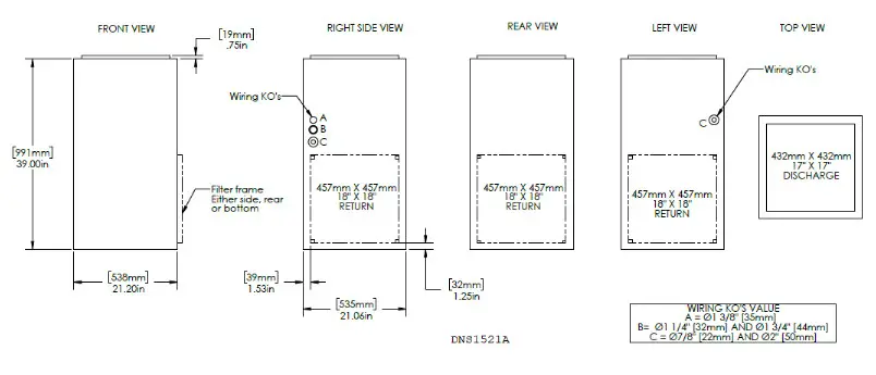
Dimensions
General Requirements and Specifications
CAUTION
This unit must be installed in a dry place, in a non-corrosive, well-ventilated environment, without excessive dust.
The ambient temperature must be over 10°C and under 27°C. If the ambient temperature is 10°C or less, the plenum must be insulated on 10 ft. linear minimum length.
- LOCATION – The furnace should be centrally located in the heating area.
- POSITIONS – It can be installed for vertical, horizontal, or downflow operation. When installed horizontally, the furnace should be positioned such as the door will not end up being on the top. The door should be on the side of the furnace, to ensure that the motor bearings are in their designed position. In vertical downflow installations, use only “L”- or “T”-shaped plenum with no openings or registers directly below the furnace.
- INSTALLATION CLEARANCES – As shipped from the factory, each unit is approved for “zero inches” clearance. If additional clearance is required, it will be indicated on the data label attached to the furnace.
- TEMPERATURE RISE – Furnaces are shipped to operate at 0.20” W.C. (50 Pa) external static pressure. They are certified for operation up to 0.50” W.C. (125 Pa). Check below for the temperature rise table on the specification chart and, if necessary, adjust the unit to match.
- SERVICE CLEARANCE – Units are serviced from the FRONT. Leave at least 24” (610 mm) clearance in front of the door.
| 240 VOLTS – SINGLE PHASE | TEMPERATURE RISE @ 0.20″ W.C. |
|||||||
| MODEL NO. | KW | BTUH | AMPS INCL. MOTOR | SUGG. BREAKER SIZE (A) | HP | °C | °F | SPEED* |
| 21B10M-A | 10 | 34121 | 46 | 60 | 1/3 | 18 | 32 | LOW |
| 21B15M-A | 15 | 51182 | 67 | 100 | 1/3 | 21 | 38 | MED |
| 21B18M-An | 18 | 61419 | 77 | 100 | 1/3 | 25 | 46 | MED |
| 21B20M-An | 20 | 68243 | 86 | 125 | 1/3 | 28 | 51 | MED |
| 21B25M-An | 25 | 85304 | 107 | 150 | 1/3 | 35 | 64 | MED |
| 208 VOLTS THREE-PHASE | ||||||||
| 83B13-A | 14. | 46064 | 42 | 60 | 1/3 | 21 | 38 | MED |
| 83B24-A’s | 25. | 84621 | 72 | 100 | 1/3 | 35 | 63 | MED |
| SPEED | FLOW RATE |
STATIC PRESSURE (INCHES OF WATER COLUMN) |
||||
| 0.2 | 0.3 | 0.4 | 0.5 | 0.6 | ||
| LOW | CFM Us | 980 462 |
950 448 |
925 436 |
905 427 |
880 415 |
| MED | CFM Us | 1240 585 |
1220 576 |
1190 562 |
1165 550 |
1135 536 |
| HIGH | CFM Us | 1420 670 |
1395 658 |
1360 642 |
1330 628 |
1280 604 |
WARNING:
*FACTORY SETTINGS.
**These models must NOT be set up to run continuously at LOW speed as it will cause overheating conditions. These models are certified to run only at HIGH and MED speeds.
SPECIFICATIONS SUBJECT TO CHANGE WITHOUT NOTICE
Operating Options
The furnace is shipped from the factory in a “Standard Heating Mode” (all switches are in the Down position). When the thermostat calls for heat, the automatic controls will be activated and the furnace turned “ON”.
The blower will run at low speed as the furnace heats up and will automatically switch to the pre-programmed heating speed when additional elements are activated by the time delay relays.
The timing of this blower speed change will depend on the size of the furnace (10 kW and 13.5 kW models do not change speed), and whether COLD or MILD is selected on the SEASON SELECT switch.
You may, however, change from the Standard Heating Mode by using the controls built into your furnace.
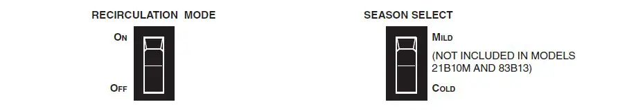
| ON – Some homeowners prefer the blower to run at low speed to more evenly distribute the air in the house. In this position, the blower will run continuously on low and automatically change to the necessary heating speed when heating elements are turned on by the thermostat. OFF – The blower motor will operate in the standard heating mode, controlled by the thermostat. |
MILD – During spring and fall, you may not require the full heating capacity to maintain a comfortable temperature. In this position, approximately half of the elements are “off-line” and will not be energized when the thermostat calls for heat. COLD – All elements are “online” and controlled by the thermostat. NOTE: If an outdoor or two-stage thermostat is used, the switch MUST be in MILD position at all times. |
Breakers
B Series furnaces are equipped with breakers, located on the front panel of the unit. These devices protect the heating elements from overcurrent. If this situation occurs, the breakers will open to cut the power from the heating elements only.
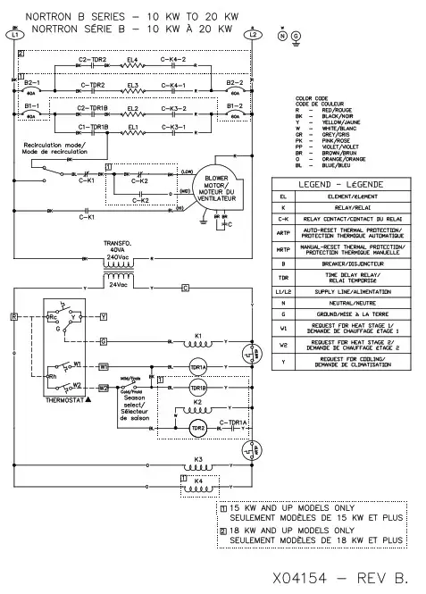
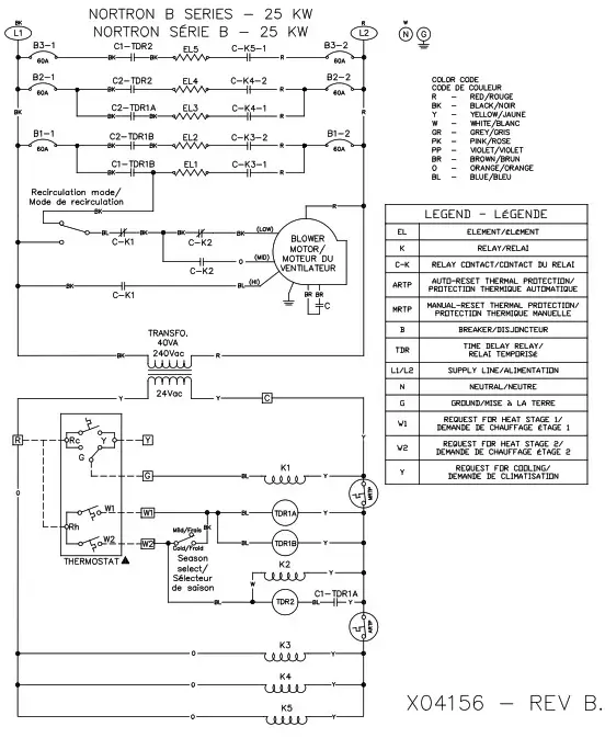
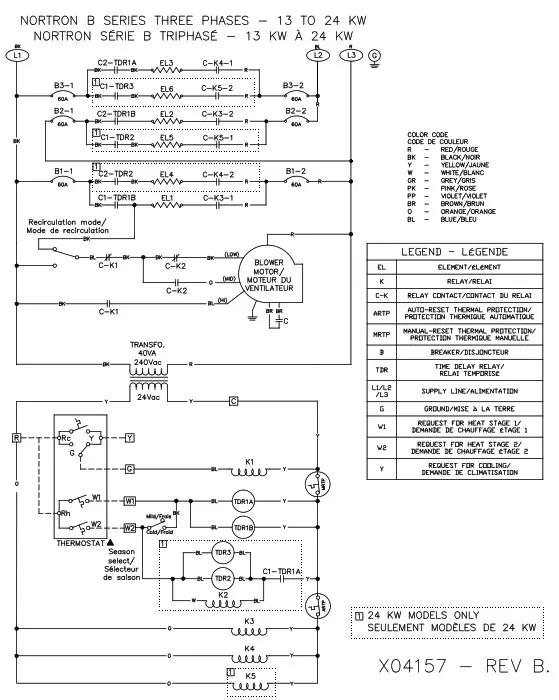
NOTE: The number of breakers varies according to the furnace model; 21B10M model has no breakers, 21B15M, 21B18M, 21B20M and 83B13 models have 2 breakers, and 21B25M and 83B24 models have 3 breakers. Refer to Section 8 Wiring Diagrams.
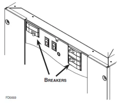
WARNING
Breakers do not cut power to the entire furnace, only to the heating elements. Do not use the breakers to turn off the furnace. The power to the whole unit can only be cut from the main electrical panel.
Installation Notes
Cold Air Return
The duct can be attached to either side, rear or the bottom of the furnace.
For side return there are four 1½” (38 mm) knockouts which can be removed and used as an outline for cutting a 18” x 18” (457 mm x 457 mm) return air opening in the furnace left or right side. Mount the filter frame to the furnace over the opening with the open side of the frame facing front. Then attach the 19” x 19” (483 mm x 483 mm) air duct to the flanges on the filter frame.
For bottom mounting, remove the screws holding the bottom plate to the furnace, discard the bottom plate and attach the filter frame to the bottom flanges with the open side of the frame facing front.
Electrica Wiring – Power Supply
The furnaces are completely factory wired. From a separate breaker, a two-wire plus ground supply wire is required for single-phase units, and a three-wire plus ground supply wire for three-phase units. The ground conductor must be firmly attached to the ground lug in the furnace and the supply wires to the terminal block in the furnace.
NOTE: When a FK120 kit is used to supply an air cleaner and/or humidifier, a third (neutral) conductor must be brought into the furnace.
WARNING
For all installations, we only recommend appropriate gauge good quality copper wire(s). However, it is the electrician’s responsibility to ensure that the wiring and connections are compliant with the latest editions of the Canadian Electrical Code and local codes.
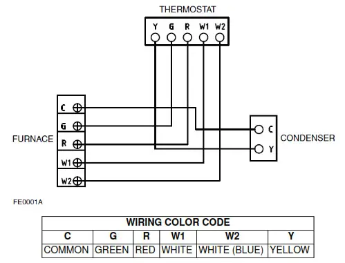
Connecting and Adjusting the Low Voltage Thermostat
Use only class 1 wires inside furnace compartments.
Attach thermostat wires to the low voltage terminal block located on the inside of the furnace. Follow the diagrams supplied with the thermostat. As a general guide, remember that the R & W terminals control single-stage heating; the R & Y terminals control cooling. Single-stage cooling uses “Y/Y2” as first and only stage. Two-stage cooling uses “Y1” as the first stage and “Y/Y2” as the second stage. Make sure the thermostat is leveled on the wall and inappropriate location as per instructions supplied with the thermostat.
CAUTION
Before turning the furnace on, the heat anticipator in the thermostat must be properly set.
Because each installation is different an accurate reading of the current draw should be made with an AC meter. Set the meter at 2 A range for furnaces through 20 kW, and at 4 A range for larger units.
A. Set the anticipator at its highest setting.
B. Disconnect the “W1” thermostat wire from the furnace low voltage terminal connections.
C. Connect the AC meter between the “W1” terminal on the board and the loose “W1” wire.
D. Turn the thermostat up to start the furnace and allow it to run, with all elements on, for three or four minutes.
E. Read the current draw on the meter and reset the anticipator to match the meter reading.
Use in Mobile Homes
Models from 10 kW to 20 kW are certified for “L”-shape and “T”shape shallow duct installation with model FSB-1 sub-base in
downflow applications when the supply air ducts pass through the floor of the structure. The recommended size of a floor opening: 14¼” x 14¼” (362 mm x 362 mm). The duct system must be designed so that the external static pressure of the system does not exceed the maximum external static pressure of 0.50” W.C. (125 Pa).
| SHALLOW DUCT AREA REQUIREMENTS | |
| DUCT DEPTH | DUCT WIDTH |
| 4″ (102 mm) | 16″ (406 mm) |
| 5″ (127 mm) | 13″ (330 mm) |
| 6″ (152 mm) | 10″ (254 mm) |
Using Optional Equipment
Two-Stage or Outdoor Thermostat
The SEASON SELECT switch must be in the MILD position. These controls can be used on all furnaces except 10 kW
model.
Follow the directions supplied with the two-stage or outdoor thermostat in conjunction with the furnace wiring diagram.
When used, the furnace stage will supply heat as follows in the opposite chart:
| Model | First Stage | Second Stage |
| 10 kW | 10 kW | – |
| 15 kW | 10 kW | 5 kW |
| 18 kW | 9 kW | 9 kW |
| 20 kW | 10 kW | 10 kW |
| 25 kW | 15 kW | 10 kW |
Air Conditioning
Your furnace is equipped with all the controls required for the addition of air conditioning (except the heat-cool thermostat).
The evaporator coil may be installed by a local contractor in a sheet metal plenum of his own manufacture.
The coil should be located: centered over the “chimney” of the furnace 4” (102 mm) to 6” (152 mm) above the top of the furnace.
Make sure no air is allowed to bypass the cooling coil during cooling operation. If the discharge opening is a great deal larger than the coil, and the ductwork is correspondingly larger than the coil, you may want to use a bypass damper for heating. The damper would be closed in summer, directing all air flow through the coil. In winter the damper would be open to allow air to bypass the coil.
Typical air-conditioning field wiring connections are shown in the diagram at right.
Wiring Diagrams
WARNING
Risk of electric shock. Disconnect power before installation, servicing, maintenance, or field wiring. Replace all panels before operating. Failure to do so can result in electric shock causing severe injuries or death.
WARNING
Risk of electric shock. Disconnect power before installation, servicing, maintenance or field wiring. Replace all panels before operating. Failure to do so can result in electric shock causing severe injuries or death.
WARNING
Risk of electric shock. Disconnect power before installation, servicing, maintenance or field wiring. Replace all panels before operating. Failure to do so can result in electric shock causing severe injuries or death.
Service Parts
In order to ensure your unit remains in good working condition, you must use Norton genuine replacement parts only. The Norton genuine replacement parts are specially designed for each unit and are manufactured to comply with all the applicable certification standards and maintain a high standard of safety. Any third-party replacement part used may cause serious damage and drastically reduce the performance level of your unit, which will result in premature failure. Also, Norton recommends contacting a certified service depot for all replacement parts and repairs.
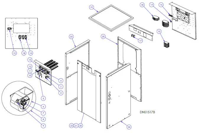
| No. | Part No. | Description |
| 2 | LO1H009 | 24V Relay (SPDT) |
| 3 | 30270024 | 24V Relay (DPST) |
| 4 | L01 H030 | 24VDC Relay (DPST) |
| 5 | 30300022 | Transformer |
| 6 | 7011035 | Blower 8 x 12 |
| 7 | L06G015 | Motor |
| 8 | B43015-02 | Blower assembly |
| 9 | L011003 | Capacitor |
| 10 | B04351-01 | Element 4kW 240V |
| 11 | B04351-02 | Element 5kW 240V |
| 12 | B04351-03 | Element 4.5kW 208V |
| 13 | R02NO28 | Automatic limit |
| No. | Part No. | Description |
| 14 | R02NO32 | Manual limit |
| 15 | L99F007 | Terminal block |
| 16 | 300270031 | Thermostat terminal |
| 17 | L07F015 | Switch |
| 18 | LO1J006 | Breaker |
| 20 | B43004-03 | Service door (2 breakers) |
| 21 | B43004-04 | Service door (3 breakers) |
| 22 | B43004-08 | Service door 3-phase |
| 23 | B43043 | Left panel |
| 24 | B43042 | Right panel |
| 25 | B43043 | Back panel |
Maintenance
MOTOR: The motor is lubricated for life and needs no oiling.
FILTERS: Size is 20” x 20” x 1” (508 mm x 508 mm x 25 mm). Should be inspected and replaced when dirty. Ordinarily, replacement is required twice per heating season and, perhaps, a third time if continuous blower operation is used.
NOTE: The elements have an automatic reset thermal cut-out which is set to open at 100°F (38°C). If it opens, the elements will be de-energized until the cut-out resets itself. In addition to that, there is manual reset thermal cut-outs that open at 130°F (54°C). If it opens, the front panel needs to be removed so the cut-out can be manually reset.
WARNING
Cut power supply (240 V or 208 V, according to the unit) before removing the front panel! Breakers of the unit do not cut power
to the entire furnace, only to the heating elements. Do not use these breakers to turn off the furnace. The power to the whole unit can only be cut from the main electrical panel.
Troubleshooting
The first step in identifying an operational problem is to determine whether the fault is in the furnace or in the thermostat and/or its connecting wiring.
- If the furnace will not start:
Turn the thermostat to its highest setting. If 24V is present between terminals C and W, the thermostat has closed, so the fault is in the furnace. Otherwise, the thermostat or its connecting wiring is the problem. - If the furnace will not turn off:
Turn the thermostat to its lowest setting. If there is no more 24V between terminals C and W and the furnace continues to run, the thermostat has opened properly and the problem resides in the furnace. Otherwise, the fault is in the thermostat or its connecting wiring. After the fault area is isolated by use of the thermostat, a check of the following components can be made more efficiently:
| Problem | Possible defective parts or components |
| 1. The furnace will not turn on. | – Thermostat – Circuit breaker or fuse is open – Motor or capacitor – RECIRCULATION MODE switch (open contact) – Sequencer – Transformer |
| 2. Motor runs continuously. | – Thermostat wires incorrectly attached to the furnace – RECIRCULATION MODE switch is not on OFF position – Sequencer (an element would also be on) – 24 V Relay) |
| 3. Elements on, but the motor does not run. | – Motor or capacitor – RECIRCULATION MODE switch (open contact) – Sequencer |
| 4. Motor going on and off in short cycles (or in too long cycles). | – Heat anticipator in the thermostat is incorrectly set or may be defective |
| 5. The thermostat must be set much higher (or lower) than the desired house temperature. | – The thermostat is not leveled or out of calibration |
| 6. Not enough heat. | – Elements or sequencers – SEASON SELECT switch set in MILD position – Safety limits opening because duct obstruction or dirty filters are restricting airflow – Defective or incorrectly wired two-stage or outdoor thermostat – Lack of enough cold air returns in house |
| 7. Two-stage or outdoor thermostat not operating properly. | – SEASON SELECT switch not set in MILD position |
| 8. Breaker on front panel trips. | – Overcurrent on the heating element. Reset the breaker. If the problem persists, call an electrician |
| 9. Thermal cut-out opens. | – Airflow is reduced because of blocked ductwork or very dirty filters |
| 10. Motor goes off, but one or more elements stay on | – Sequencer |
| 11. Automatic speed change doesn’t occur when the furnace heats up. | – Sequencer – Relay |
Warranty
SIXTY-MONTH LIMITED WARRANTY FOR NORTON PRODUCTS
Norton warrants to the original consumer purchaser of Notron products that such products will be free from defects in materials or workmanship for a period of sixty (60) months from the date of original purchase. THERE ARE NO OTHER WARRANTIES, EXPRESS OR IMPLIED, INCLUDING, BUT NOT LIMITED TO, IMPLIED WARRANTIES OR MERCHANTABILITY OR FITNESS FOR A PARTICULAR PURPOSE.
During this sixty-month period, Norton will, at its option, repair or replace without charge, any product or part which is found to be defective under normal use and service. This product or part should be shipped prepaid by the customer to the company factory or the nearest authorized service center.
THIS WARRANTY DOES NOT EXTEND TO FILTERS, FURNACE KITS SOLD SEPARATELY, DUCTS, AND
ACCESSORIES FOR DUCTING. This warranty does not cover (a) normal maintenance and service or (b) any products
or parts which have been subject to misuse, negligence, accident, improper maintenance or repair (other than by Norton), faulty installation or installation contrary to recommended installation instructions. Norton does not accept any responsibility for transportation of repaired parts or replaced product mentioned above and for reinstallation costs.
The duration of any implied warranty is limited to the sixty-month period as specified for the express warranty. Some jurisdictions do not allow limitations on how long an implied warranty lasts, so the above limitation may not apply to you.
NORTON’S OBLIGATION TO REPAIR OR REPLACE, AT NORTON’S OPTION, SHALL BE THE PURCHASER’S OLE AND EXCLUSIVE REMEDY UNDER THIS WARRANTY. NORTON SHALL NOT BE LIABLE FOR INCIDENTAL,
CONSEQUENTIAL OR SPECIAL DAMAGES ARISING OUT OF OR IN CONNECTION WITH PRODUCT USE OR PERFORMANCE. Some jurisdictions do not allow the exclusion or limitation of incidental or consequential damages, so the above limitation or exclusion may not apply to you.
This warranty gives you specific legal rights, and you may also have other rights, which vary from one province to another.
This warranty supersedes all prior warranties and applies only to Canada’s territorial limits.
To qualify for warranty service, you must (a) notify Norton at the address or telephone number stated below, (b) give the model number and part identification, and (c) describe the nature of any defect in the product or part. At the time of requesting warranty service, you must present evidence of the original purchase date.
3400 Boul. Industriel, Sherbrooke, QC, J1L 1V8
www.dettson.com
800-567-2733