ORATH Power Supply Instruction Manual

Installation
The 2500-PWR24U is designed for use with RATH® signaling devices and systems (SmartRescue Base Station and 2100 Series Phones)
Wiring methods shall be in accordance with NFPA 72 and with all local codes and Authorities Having Jurisdiction.
- Mount the 2500-PWR24U in the desired location near the power source and power runs for the devices.
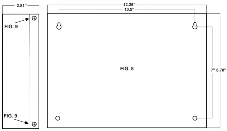
- Mark and predrill holes in the walls to line up with the top two keyholes in the enclosure (Fig. 8, pg. 6).
- Install two upper fasteners and screws in the wall, with the screw heads protruding.
- Place the enclosure’s upper keyholes over the two upper screws and mark the position of the lower two holes.
- Remove the enclosure, drill the lower holes, and install two fasteners.
- Place the enclosure’s upper keyholes over the upper screws, install the lower two screws, and tighten all of the screws.
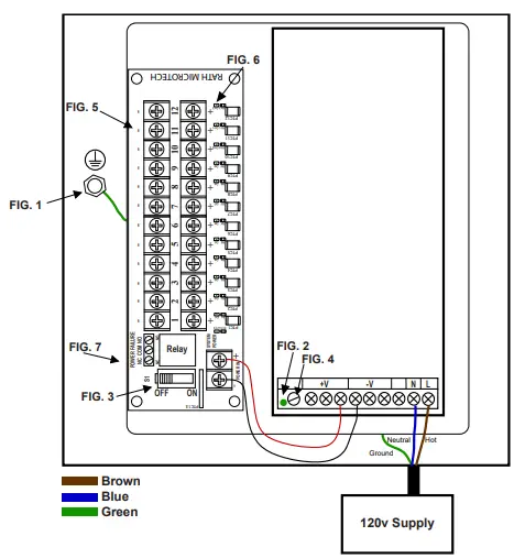
- Connect earth ground to
 the terminal located within the enclosure (Fig. 1, pg. 4)
 - . Connect the three-prong 120vac power cord to the AC input (100-120vac, 50/60Hz).
Note: The green LED on the 2500-PWR24U will illuminate when power is present (Fig. 2, pg. 4) - The slide switch S1 should be in the OFF position for 24vdc (Fig. 3, pg. 4). Measure the DC voltage using the rim potentiometer SVR1 and adjust to 24vdc if necessary (Fig. 4, pg. 4).
- Select the appropriate knockouts on the enclosure for routing the low voltage devices.
- Connect each low voltage device (SmartRescue Base Station and 2100 Series Phones) to each output terminal 1 – 12 (Fig. 5, pg. 4).
Note: The SmartRescue and 2100 Series Phones are NOT polarity sensitive.
Note: 18AWG or larger wire is recommended to connect devices. Keep power-limited circuits separate from
non power-limited wiring (120vac). - Move the slide switch S1 to the ON position (Fig. 3, pg. 4).
Note: All LEDs on the output board will illuminate green when power is present (Fig. 6, pg. 4). - Recheck the output voltage to confirm that the connected devices have not caused the level to drop. If required, adjust the output voltage to 24vdc using the trim potentiometer SVR1 (Fig. 4, pg. 4).
- Once wiring is complete, secure the enclosure door with the supplied screws (Fig. 9, pg. 6).
- The power cord plug MUST be secured to the receptacle using the included Power Cord Plug Bracket Assembly (Fig. 10, pg. 6).
Wiring Diagram
Note:
A three-prong plug is included with the 2500-PWR24U.
Note:
The 2500-PWR24U is enabled with DC Fail Supervision using contact closures which indicate loss of DC power. Example: The contact closures can be connected to an annunciator alarm panel (Fig. 7, pg. 4). The relay is normally energized when DC power is present. Loss of DC power will trip the annunciator alarm panel.
Specifications
Input
- 100-120vac, 50/60Hz, 4.0A
Output:
- 24vdc @8.5A total continuous output
- Filtered and electronically regulated output
- 12 PTC protected outputs @0.500A current limited
- Class 2
- 24vdc adjustable output
- 24vdc S1 on/off switch
- Input and output status LED indicators
Protection
- Short Circuit/Overload/Over Voltage
Supervision:
- DC power failure supervision (form C contacts)
Environmental:
- For indoor use ONLY
- Operating temperature 32° F to 120° F (0° C to 49° C) ambient
Terminal Identification:
| Terminal Legend | Function/Description |
| L, G, N | Connections for VAC terminals: L to Hot, N to Neutral, Ground to Chassis |
| + DC – | 24vdc @8.5A cotinuous power limited output |
| DC Power Failure | Indicates loss of DC power, e.g. connect to annunciator/alarm panel |
| NC, C, NO | Relay normally energized when DC power is present. Contract rating at 1A @ 28vdc. |
| Used for making connection from enclosure to earth ground |
Power Distribution Module:
| 1+ to 12+ | Positive DC power outputs |
| 1- to 12- | Negative DC power outputs |
Maintenance
Under normal conditions, the 2500-PWR24U should be checked for proper operation annually. It is recommended to check the output voltage and verify that 24vdc is present under normal load conditions. It is also recommended to check the current draw to ensure that the current is within specifications.
Troubleshooting
| Problem | Possible Cause & Solutions |
| Green power LEDs are not illuminated: |
|
| Device does not have power: |
|
Mounting


