PATRIOT 356-9448 Dual Head Security Light

PACKAGE CONTENTS
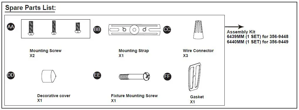
HARDWARE CONTENTS
Note: Hardware not shown actual size.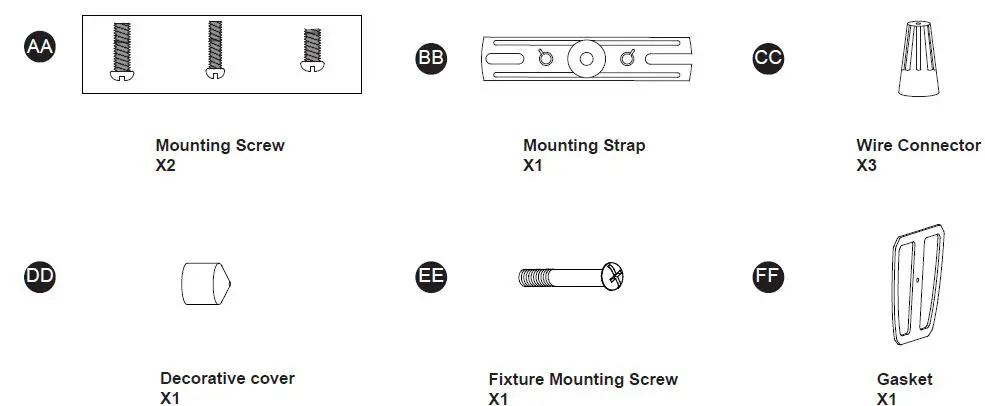
SAFETY INFORMATION
Please read and understand this entire manual before attempting to assemble, operate or install the product.
WARNING
- Turn off electricity at main fuse box (or circuit breaker box) before beginning installation by removing fuse (or switching off circuit breaker).
- Be careful not to damage or cut the wire insulation (covering) during fixture installation. Do not permit wires to contact any surface having a sharp edge. To do so may damage or cut the wire insulation, which could cause serious injury or death from electric shock.
CAUTION
- All electrical connections must be in agreement with local codes, ordinances or the national electric code (NEC). Contact your municipal building department to learn about your local codes, permits and/or inspections.
- Risk of fire – most dwellings built before 1985 have supply wire rated for 140°F/60ºC. Consult a qualified electrician before installation.
- Do not connect this fixture to an electrical system that does not provide a means for equipment grounding. Never use a fixture in a two-wire system that is not grounded. If you are not sure your lighting system has a grounding means, do not attempt to install this fixture. Contact a qualified, licensed electrician for information with regards to proper grounding methods as required by the local electrical code in your area.
- Only general ON/OFF wall switch applies for this fixture, the dimmable wall switch shouldn’t be required.
- Rated Wattage: 32 W
- Working Temperature Range: -13ºF ~ 113ºF
PREPARATION
Before beginning assembly, installation or operation of product, make sure all parts are present. Compare parts with package contents list and diagram on previous page. If any part is missing or damaged, do not attempt to assemble, install or operate the product. Contact customer service for replacement parts. Tools Required for Assembly (not included): Slotted Screwdriver, Phillips Screwdriver, Pliers, Electrical Tape, Wire Cutters, Safety Glasses, Ladder, Wire Stripper.
ASSEMBLY INSTRUCTIONS
Important to Know
- This fixture requires a 120 VAC, 60 Hz power source.
- For general safety and to avoid any possible damage to the sensor, be sure the power is switched “off” before adjustment.
- Motion sensor: turns light ON automatically when motion is detected and turns light down to lower level or OFF automatically when motion stops.
- Photocell keeps the light OFF during daylight hours.
Note: Fixture can be wall mounted or eave mounted.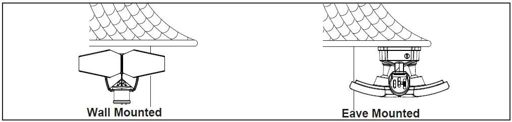
Light fixture and sensor should be mounted as shown above when installed (depending upon type of installation) Before installing the light fixture under an eave, the sensor head must be rotated as shown in the next two steps for proper operation and to avoid the risk of electrical shock.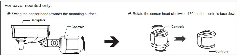
Installation Steps Turn off the power at fuse or circuit box.
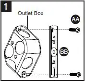
- Install the mounting strap (BB) to the outlet box with the stamped word “FRONT” facing away from the outlet box, using two mounting screws (AA) that best fit the outlet box. (Choose one matching pair of suitable mounting screws from the 3 pairs provided)
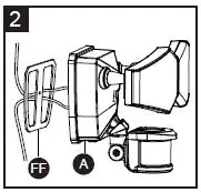
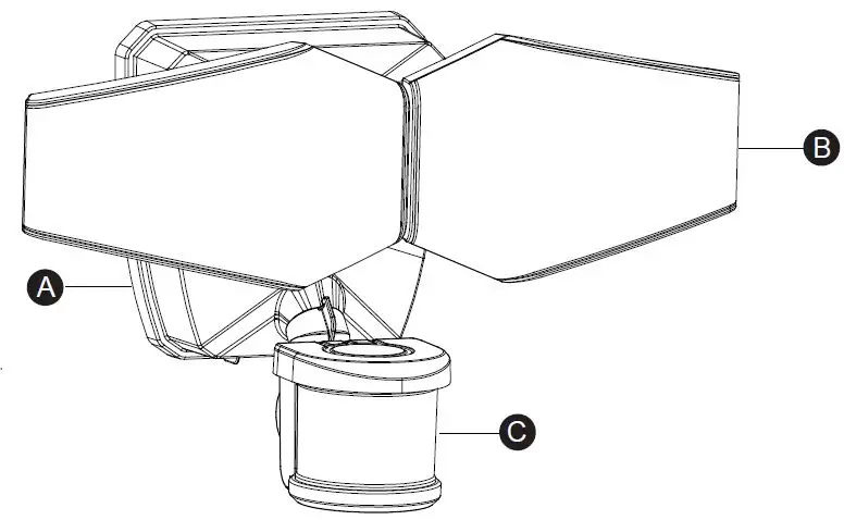
- Thread the fixture wires through gasket (FF), and then attach the gasket (FF) into backplate of the light fixture (A).
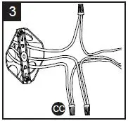
- Connect the house grounding wire and the fixture grounding wire (green/yellow) using the wire connector (CC). Connect the fixture black wire to the house black wire and the fixture white wire to the house white wire CC using wire connector (CC) provided. Carefully tuck the wires back into the outlet box.
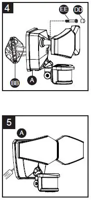
- Attach the backplate of the light fixture (A) to the mounting strap (BB) by secure it with the fixture mounting screw (EE). Push the decorative cover (DD) firmly into the fixture mounting screw hole on the light fixture (A).
- Use silicone caulking compound (not included), caulk completely around where the backplate of the light fixture (A) meets the wall surface.
CAUTION: Be sure to caulk completely where the backplate meets the wall surface to prevent water from seeping into the light fixture (A) and outlet box.
Adjusting the Sensor Head:
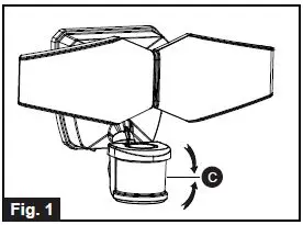
- Aim sensor head (C) toward desired detection area, maintaining a 5° – 40° downward angle to allow moisture to drain.
Note: Make sure sensor head is positioned with control knob facing towards the ground. - You can rotate the sensor head up and down to change the coverage area. (See Fig.1)
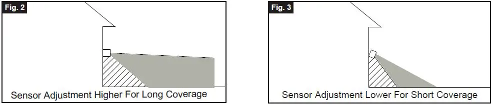
- Note: Range set too high may increase false triggering. (See Fig.2, Fig.3)
Adjusting the Light Head:
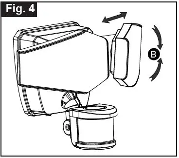
- Gently grasp the light heads (B) and tilt them up or down, left or right to adjust the light coverage area. Keep the light heads (B) at least 1” (25mm) away from the sensor. (See Fig. 4)
- Keep the light heads (B) 30˚ below horizontal to avoid water damage and electrical shock.
FUNCTION AND OPERATION
Sensitivity of Motion Sensor: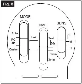
- You can adjust the sensitivity of the motion sensor by using the “Sens” selector located on the bottom surface of the sensor. (See Fig.5)
- Adjust motion sensor sensitivity to HIGH (H), MEDIUM (M), or LOW (L) to achieve desired performance.
- Approximate range for each setting: 30 ft. (L), 50 ft. (M), 70 ft. (H).
Choose a mode by sliding the switch on the bottom of the sensor. (See Fig.5) Note: When power is first applied, the light will turn on to 100% brightness. The sensor will take 30 seconds to warm up.
- TEST MODE (daytime and nighttime operation.)
- Slide the Time switch the “Test” position.
- The light turns to high-level brightness (5000K) when motion is detected, and stays on as long as the motion continues.
- Then it revert back to 2700K CCT Color and the low-level brightness (0~50%) as per setting about 5 seconds after motion is no longer detected.
- AUTO MODE (nighttime operation only)
- To “AUTO” mode, slide the Time switch to the desired time setting (30s/1min/3min). At dusk, the light turns on to pre-selected low-level brightness (2700K). When motion is detected, the light turns to high-level brightness (5000K) and stays on as long as motion continues. When the motion is no longer detected, the light at high-level brightness (5000K) remains on for the predetermined time you set (30s/1min/3min), then switches back to pre-selected low-level brightness (2700K) automatically.
- The light turns off automatically at dawn.
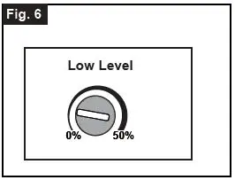
Note: You can adjust the low-level brightness(0~50%) by using the low-level brightness(0~50%) knob on the backplate (See Fig.6).
- PC MODE (nighttime operation only)
- In “PC” mode, the light will turn on at full brightness (5000K) at dusk and remains on until dawn. pre-selected low-level brightness (2700K). It turns to high-level brightness (5000K) when motion is detected, and stays on as long as motion continues. When motion is no longer detected, it remains on for the predetermined shut-off delay time you set (30s/1min/3min), then returns to the pre-selected low-level brightness (2700K) automatically.
- The light turns off automatically at dawn.
Note: You can adjust the low-level brightness(0~50%) by using the low-level brightness(0~50%) knob on the backplate (See Fig.6).
- CUSTOM MODE (nighttime operation only):
- In “CUSTOM” mode, the light turn on full brightness (2700K) at dusk and off at dawn automatically.
- Set motion sensor operation to go on at a specific time.
Turn the wall switch “OFF”, and turn it “ON” twice within Turn wall switch OFF-ON-OFF-ON 3 seconds. The light will go into motion-sensor operation at in 0.5~3 Seconds
the specified time every night. The light turns off automatically at dawn. - For example, a homeowner wants to have the light stay on high-level brightness from dusk to 8pm, and would like the light Turn wall switch OFF-ON-OFF-ON to go into “AUTO” motion sensor mode. To achieve this, the in 0.5~3 Seconds light homeowner will turn the wall switch “OFF”, and turn it “ON” twice within 3 seconds. This sets the time the light goes into “AUTO” mode every day, the light will behave the same way. To revert back to Default, turn the wall switch “OFF” and then turn it “ON” after 5 seconds. Note: You can adjust the low-level brightness(0~50%) by using the low-level brightness(0~50%) knob on the backplate (See Fig.6). When light units are linked, the Set motion sensor operation to go at a specific time is also linked when MODE settings are in Custom.
- RF Linking Network Setup
- From all the light units, select one as the main unit and the others as the sub-units;
First to setup all the sub-units by press the Link button twice within 3 seconds, the sub-units will flash once every 1 second meaning it is waiting to receive matching signal from the main light.
Then to setup the main unit by press and hold the Link button for 5 seconds, the main unit will flash slowly
(once every 3 seconds), and when the sub-units have paired with the signal, the sub-units will stop flashing confirming it have paired with the main unit. (if pairing not successful, the sub-unit will keep flashing).
When all the sub-units have stop flashing, press the Link button on the main unit once to complete the pairing process.(the main unit will stop flashing)
After complete the pairing process, any light within the Link group range can send or receive the photo sensor or motion sensor signal from the other light and response accordingly.
Note: Maximum link up to 10 units per link group, each light can link within 120ft apart.
- From all the light units, select one as the main unit and the others as the sub-units;
- RF Linking
- Photo Sensor Linking When the Photo Sensor detect that the ambient brightness is less than the LUX set value.
- In “Auto” mode, the light turns on to Low-Level brightness (2700K) and send out a comprehensive signal.
- Linking other lamps set in “Auto” mode to enter Low-Level brightness
- Linking other lamps set in “3H”, “PC”, or “Custom” mode to enter High-Level brightness.
- In “PC”, “3H”, or “Custom” mode, the light turns on to High level brightness and send out a comprehensive signal.
- Linking other lamps set in “Auto” mode to enter Low-Level brightness (2700K).
- Linking other lamps set in “PC”, or “3H” mode to enter High-Level brightness (5000K).
- Linking other lamps set in “Custom” mode to enter High-Level brightness (2700K).
- When the Photo Sensor detects that the ambient brightness is greater than the LUX set value,
- comprehensive signal from the volunteers to inform all the Linking lamps to turn off automatically.
- Motion Detect Linking When the Motion Sensor detects
- In “Auto” mode, the lamp sends out a comprehensive signal to all the linked lamps to automatically switch to High-Level brightness (5000K) and remains on for predetermined time you set (30s/1min/3min).
- In “3H” or “Custom” mode,
- During the start of “3H” or “Custom” mode, the lamp will remain High-Level brightness and turn off the motion sensor until 3 hours or the custom set time is up.
- Once the “3H” or “Custom” set time is up, the lamp will turn on motion sensor and switch to “Auto” mode where the lamp sends out a comprehensive signal to all the linked lamps to automatically switch to High-Level brightness (5000K) and remains on for predetermined time you set (30s/1min/3min).
- Unlink the unit from the Link Group
- Press and hold the Link button on the sensor head for 3 seconds, the light will flash 3 times to confirm reset and remove from the Link Group. All lights will need to be reset before setup the Link Group. Strongly recommended to set all the linked lights to the same MODE to avoid any confusion of function error.
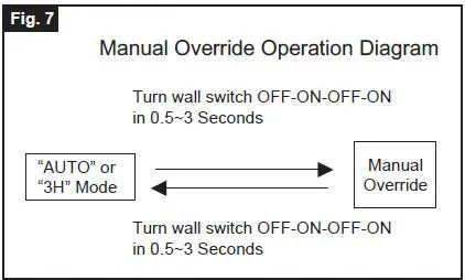
- Manual Override (nighttime operation only)
- To temporarily override the settings in “AUTO” or “3H” mode for on-demand continuous high-level brightness at night, turn the wall switch “OFF” then turn it “ON” twice within 3 seconds, the light remains on all night long. To shift back to “AUTO” or “3H” mode, turn the wall switch “OFF” then turn it “ON” twice within 3 seconds again.(See Fig.7)
- The light turns off automatically at dawn.
Note: When light units are linked, the Manual Override action is also linked when MODE settings are in Auto or 3H.
- Customization Options: Shut-off Delay
- The shut-off delay is the length of time the light will stay at brightness after motion is detected.
- You can set the shut-off delay by push the switch so it points to the desired time setting (30s/1min/3min).
Notes:
- The sensitivity of the motion sensor will increase as the environmental temperature gets cooler. For best performance, gently clean the lens with a soft cloth every 1 or 2 months to ensure maximum sensitivity.
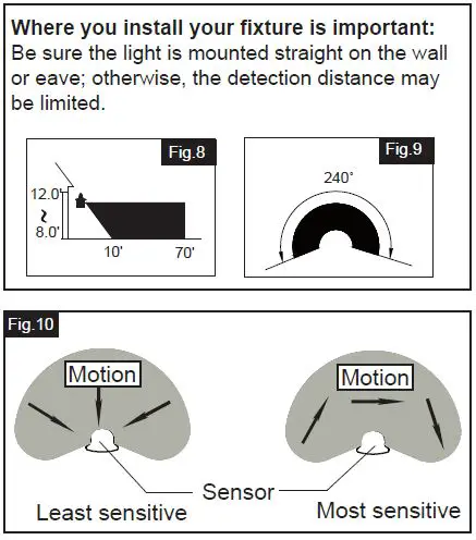
- For best performance, install fixture at least 8 feet above the ground. At such a height, the fixture will provide a detection distance of up to 70 feet at 77 degrees Fahrenheit. (See Fig.8)
- The sensor detects movement across a detection range of 240 degrees. (See Fig.9)
- The sensor will be more sensitive to motion across its detection path than motion directly towards it. (See Fig.10)
- To reduce possible nuisances, do not mount the fixture near a heat source like an air conditioner, vent or furnace exhaust, or in a direction facing any reflective object or other nearby light source.
The following parts are available for reorder if damaged or missing. Call our toll free at 1-800-887-6326.
CARE AND MAINTENANCE
- To prolong the original appearance, clean the light fixture with clear water and a soft, damp cloth only.
- Do not use paints, solvents, or other chemicals on this light fixture. They could cause a premature deterioration of the finish. This is not a defect in the finish and will not be covered by the warranty.
TROUBLESHOOTING
| Problem | Possible Cause | Solution |
| The light will not come on. | The light switch is turned off.
The fuse is blown or the circuit breaker is turned off. Daylight turn-off (photocell) is in effect. The circuit wiring is incorrect (if this is a new installation). The motion sensor is aimed in the wrong direction. The outside air temperature is close to the same as a person’s body heat. |
Turn the light switch on.
Replace the fuse or turn the circuit breaker on. Recheck after dark.
Verify the wiring is correct.
Re-aim the motion sensor to cover the desired area. Increase the “SENS” setting. |
| The light comes on during the day. | The motion sensor may be installed in a relatively dark location.
The “TIME” switch is in the “TEST” position. |
The light fixture is operating normally under these circumstances
Set the “TIME” switch to the 30s, 1min,3min setting. |
| The light comes on for no apparent reason. | The motion sensor may be sensing small animals or automobile traffic.
The “SENS” switch is set too high. The outside temperature is much warmer or cooler than a person’s body heat (summer or winter). The light fixture is wired through a dimmer or timer. |
Decrease the “SENS” setting or reposition the motion sensor.
Decrease the “SENS” setting. Decrease the “SENS” setting.
Do not use a dimmer or timer to control the light fixture. Replace the dimmer or timer with a standard on/off wall switch. |
| The lights turn off too late in the PC setting. |
The light fixture may be installed in a relatively dark location. |
Relocate the light fixture or use the 3 hour setting. |
|
The lights stay on continuously. |
The motion sensor may be picking up a heat source, such as an air vent, dryer vent, or brightly painted,
heat-reflective surface. The motion sensor is in manual mode.
The light fixture is wired through a dimmer or timer.
The light fixture is on the same circuit as a motor, transformer, or fluorescent bulb. |
Decrease the “SENS” setting or reposition the motion sensor.
Switch the motion sensor to auto. See Using manual mode on page 5. Do not use a dimmer or timer to control the light fixture. Replace the dimmer or timer with a standard on/off wall switch. Install the light fixture on a circuit without motors, transformers, or fluorescent bulbs. |
| Problem | Possible Cause | Solution |
| The lights flash on and off. | Heat or light from the lamp heads may be turning the motion sensor on and off.
Heat is being reflected from other objects and may be turning the motion sensor on and off. The motion sensor is in “TEST” mode and warming up. |
Reposition the lamp heads away from the motion sensor.
Decrease the “SENS” setting or reposition the motion sensor.
While in “TEST” mode, the light only stays on for 30 seconds. Set the “TIME” switch to 30s,1min,3min. |
|
The lights flash once then stay off in manual mode. |
The motion sensor is detecting light from
the lamp heads. |
Reposition the lamp heads to keep the area below the motion sensor relatively dark. |
If unable to fix any of the above issues, please consult a certified electrician.
FIVE-YEAR LIMITED WARRANTY: If, during normal use, this PATRIOT LIGHTING R lighting fixture breaks or fails due to a defect in material workmanship within five (5) years from the date of original purchase, simply bring this lighting fixture with the original sales receipt back to your nearest MENARDS retail store.R At its discretion, PATRIOT LIGHTING agrees to have the product or any defective part(s) repaired or replaced with the same or similar PATRIOT LIGHTING product or part free of charge, within the stated warranty period, when returned by the original purchaser with original sales receipt. This warranty; (1) excludes expendable parts including but not limited to light bulbs; (2) does not cover damage that has resulted from abuse or misuse; and (3) does not cover any losses, labor, injuries to persons/property or costs. This warranty does give you specific legal rights and you may have other rights, which vary from state to state.
FCC Statement
This device complies with Part 15 of the FCC Rules. Operation is subject to the following two conditions:
(1) this device may not cause harmful interference, and (2) this device must accept any interference received, including interference that may cause undesired operation.
Changes or modifications to this unit not expressly approved by the party responsible for compliance could void the user’s authority to operate the equipment.
NOTE: This equipment has been tested and found to comply with the limits for a Class B digital device, pursuant to Part 15 of the FCC Rules. These limits are designed to provide reasonable protection against harmful interference in a residential installation. This equipment generates uses and can radiate radio frequency energy and, if not installed and used in accordance with the instructions, may cause harmful interference to radio communications.
However, there is no guarantee that interference will not occur in a particular installation. If this equipment does cause harmful interference to radio or television reception, which can be determined by turning the equipment off and on, the user is encouraged to try to correct the interference by one or more of the following measures:
- Reorient or relocate the receiving antenna.
- Increase the separation between the equipment and receiver.
- Connect the equipment into an outlet on a circuit different from that to which the receiver is connected.
- Consult the dealer or an experienced radio/TV technician for help.