Phantom FC40 User Manual
Thank you for purchasing our product. Read the entire manual strictly and follow these steps to use you product. Please visit the DJI website, PHANTOM FC40 section to confirm if the manual is the latest one according to the manual version. If not, please download and refer to the latest manual.
Note: The built-in autopilot system is NAZA-M V2; you can obtain the current NAZA-M V2 Firmware Version according to the Assistant Software. If you ever upgrade your NAZA-M V2 Firmware, please carefully read the corresponding NAZA-M V2 release note and NAZA-M V2 quick start guide.
If you have any problem you cannot solve during installation and usage , please contact a DJI authorized dealer or DJI customer service.
Disclaimer and Warning
Please read this disclaimer carefully before using the product. By using this product, you hereby agree to this disclaimer and signify that you have read them fully. THIS PRODUCT IS NOT SUITABLE FOR PEOPLE UNDER THE AGE OF 18. PHANTOM FC40 is an excellent flight platform offering an excellent flight experience, only if it is powered normally and in a good working condition. Despite the product having a built-in autopilot system and our efforts in making the operation of the controller as safe as possible when the power battery is connected, we strongly recommend users to remove all propellers when calibrating and setting parameters. Make sure all connections are good, and keep children and animals away during firmware upgrade, system calibration and parameter setup. DJI Innovations accepts no liability for damage(s) or injuries incurred directly or indirectly from the use of this product in the following conditions:
- Damage(s) or injuries incurred when users are drunk, taking drugs, drug anesthesia, dizziness, fatigue, nausea and any other conditions no matter physically or mentally that could impair your ability.
- Damage(s) or injuries caused by subjective intentional operations.
- Any mental damage compensation caused by accident.
- Failure to follow the guidance of the manual to assemble or operate.
- Malfunctions caused by refit or replacement with non-DJI accessories and parts.
- Damage(s) or injuries caused by using third party products or fake DJI products.
- Damage(s) or injuries caused by mis-operation or subjective mis-judgment.
- Damage(s) or injuries caused by mechanical failures due to erosion, aging.
- Damage(s) or injuries caused by continued flying after low voltage protection alert is triggered.
- Damage(s) or injuries caused by knowingly flying the aircraft in abnormal condition (such as water, oil, soil, sand and other unknown material ingress into the aircraft or the assembly is not completed, the main components have obvious faults, obvious defect or missing accessories).
- Damage(s) or injuries caused by flying in the following situations such as the aircraft in magnetic interference area, radio interference area, government regulated no-fly zones or the pilot is in backlight, blocked, fuzzy sight, and poor eyesight is not suitable for operating and other conditions not suitable for operating.
- Damage(s) or injuries caused by using in bad weather, such as a rainy day or windy (more than moderate breeze), snow, hail, lightning, tornadoes, hurricanes etc.
- Damage(s) or injuries caused when the aircraft is in the following situations: collision, fire, explosion, floods, tsunamis, subsidence, ice trapped, avalanche, debris flow, landslide, earthquake, etc.
- Damage(s) or injuries caused by infringement such as any data, audio or video material recorded by the use of aircraft.
- Damage(s) or injuries caused by the misuse of the battery, protection circuit, RC model and battery chargers.
- Other losses that are not covered by the scope of DJI Innovations liability.
Product Usage Cautions
Please check the following steps carefully before every
- Before use of the product, please accept some flight training (Using a simulator to practice flying, getting instruction from a professional person, etc.).
- Check that all parts of the product are in good condition before flight. Do not fly with aging or broken parts.
- Check that the propellers and the motors are installed correctly and firmly before flight. Make sure the rotation direction of each propeller is correct. Do not get close to or even touch the working motors and propellers to avoid serious injury.
- Do not over load the aircraft (The total weight should be less than 1200g).
- Make sure that the transmitter battery and the flight battery are fully charged.
- Try to avoid interference between the transmitter and other wireless equipment.
- Make sure to switch on the transmitter first, and then power on the aircraft before takeoff! Power off the aircraft first, and then switch off the transmitter after landing!
- Fast rotating propellers will cause serious damage and injury. Always fly the aircraft 3m or above away from you and the unsafe conditions, such as obstacles, crowds, high-voltage lines, etc. FLY RESPONSIBLY.
- All parts must be kept out of the reach of children to avoid CHOKE HAZARD; if a child accidentally swallows any part you should immediately seek medical assistance.
- Always keep the compass module away from the magnet. Otherwise it may damage the compass module and lead the aircraft to work abnormally or even be out of control.
- DO NOT use the PHANTOM FC40 transmitter (receiver) with the other third party remote control equipment.
- Make sure to use the NAZA-M Assistant Software of 2.20 version (or above) to carry out the firmware upgrade and parameter configuration.
- Built-in ESCs of PHANTOM FC40 ONLY support 3S (11.1V) power supply.
- ONLY use the DJI original motor and propeller.
- If you want to put the PHANTOM FC40 in a car, please keep it away from the speaker, since the compass module may be magnetized.
- DO NOT use the magnetic screwdriver. Otherwise, keep the screwdriver at least 10cm away from the compass module, to avoid magnetic interference.
- For Mac user, please install the Windows system to run the Assistant Software.
Trademarks
DJI and PHANTOM are registered trademarks of DJI Innovations. Names of product, brand, etc., appearing in this manual are trademarks or registered trademarks of their respective owner companies. This product and manual are copyrighted by DJI Innovations with all rights reserved. No part of this product or manual shall be reproduced in any form without the prior written consent or authorization of DJI Innovations. No patent liability is assumed with respect to the use of the product or information contained herein.
Battery Usage and Charging Cautions
- Do not put the battery into water; store the battery in a cool and dry environment.
- Only use the correctly specified batteries.
- Batteries must be kept out of the reach of children; if a child accidentally swallows the battery you should immediately seek medical assistance.
- Do not use or store the battery near fire.
- Battery should be charged with a DJI authorized charger.
- Do not connect the battery reversed in positive and negative terminals in the charger or equipment.
- Do not connect the battery directly to the wall plugs or vehicle-mounted socket.
- Do not put the battery into a fire or heat the battery.
- Do not let the battery terminals (+and-) touch together to cause short-circuit.
- Do not transport or store the battery together with metal objects.
- Do not hit or throw the battery.
- Do not weld the battery terminals together.
- Do not drive a nail in, hit with a hammer, or stomp on the battery.
- Do not disassemble or alter the battery.
- Do not use or store the battery in extreme heat environments, such as direct sunlight or in the car in hot weather. Otherwise, the battery will overheat, may cause fire (or self-ignite), this will affect the performance of the battery, shorten the service life of the battery.
- Do not use the battery in strong electrostatic areas, otherwise the electronic protection may be damaged which may cause a hazard.
- If you get the battery electrolyte leakage into your eyes, don’t rub, first wash your eyes with clean water then seek medical assistance immediately. If not handled in a timely manner, eyes could be damaged.
- Do not use the battery when it emits an odour, high temperature, deformation, change in color or other abnormal
phenomena; if the battery is in using or charging, you should stop charging or using immediately. - If the battery terminal gets dirty, please clean it with a dry cloth before using. Otherwise it will cause a poor contact, thus causing energy loss or inability to charge.
- Discarded battery could lead to a fire; you should completely discharge the battery and wrap the output terminal with insulating tape before discarding.
- DO NOT drain the battery or leave the battery plugged into the PHANTOM FC40 when unused. When there is low voltage alert please landing timely to avoid damages to the battery or others.
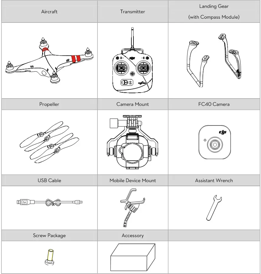
In the Box
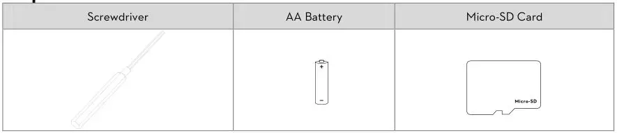
Required Items
Introduction
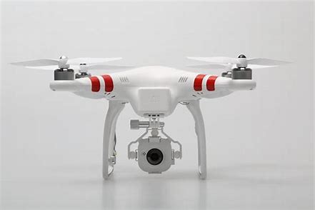
The PHANTOM FC40 is an all-in-one, ready-to-fly small quadcopter designed for people just getting started in aerial photography. Before shipping from the factory, it has been configured and fully tested, which means you have no configuration to do.
Aircraft
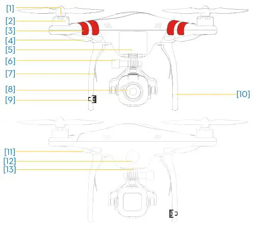
- Propeller
- Motor
- Nose Direction
- Nose Indicator (red LED)
- Battery Compartment
- Camera Mount
- Receiver Antenna
- Camera
- Compass
- Landing Gear
- Rear Indicator (green LED)
- LED Flight Indicator
- Micro-USB (on the bottom)
Built-in
a) NAZA-M V2 Autopilot System (Refer to NAZA-M V2 manual for details)
b) GPS Module
c) Compass Module
d) R/C Receiver
e) Power System for Flight
f) LED Flight Indicator
Functions
a) ATTI./GPS Mode (Manual Mode and Failsafe Switch is selectable)
b) Intelligent Orientation Control (IOC)
c) Enhanced Fail-Safe
d) Low Voltage Alert
e) Assembled with FC40 Camera
f) DJI FC40 App
Transmitter
![]()
![]()
- Antenna
- Carrying Handle
- Mode Control Switch S1
- IOC Switch S2
- Stick (J1: Roll [left&right], J2: Pitch [front&back])
- Stick (J3: Throttle [up&down], J4: Yaw [rotation])
- Neck Strap Attachment
- Power Switch
- Power Indicator
- Battery Compartment (On the back)
- Potentiometer (On the back) (For Compliance version configuration)
Parameters Operating Frequency : 5.728 GHz-5.85 GHz
Communication Distance (open area): CE 300m; FCC 500m
Receiver Sensitivity (1%PER): -93dBm
Transmitting Power (EIRP): CE 25mw; FCC 125mw
Working Current/Voltage : 80 mA@6V
Battery: 4 AA Batteries
Transmitter Operation
Definitions
The ‘stick neutral’ positions and ‘stick released’ mean the control sticks of the transmitter are placed at the central position.
To ‘move the stick’ means that the stick of transmitter is pushed away from the central position.
![]()
![]()
You can change the operation mode of the Transmitter according to the “PHANTOM RC Assistant Software Description” section if necessary.
Link between the Transmitter and Receiver
There is a 5.8G receiver in the PHANTOM FC40, with the link button and indicator located in the battery compartment. The link between the transmitter and aircraft is already established for you so you can initially skip this procedure. If you ever replace the transmitter, re-establishing the link is required.
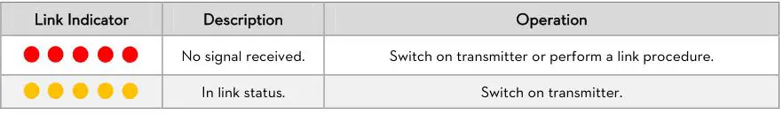
Link Procedures
- Power off transmitter and power on aircraft. You will see the link indicator blinking red.
- Press link button and hold until the link indicator blinks yellow. Release the link button.
- Power on transmitter and link indicator should switch off. This indicates that the link has been successfully established.
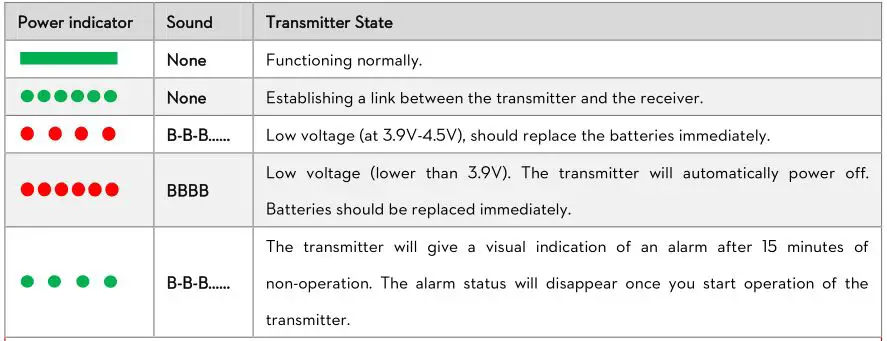
Link Indicator
Before Flying
Installing the Transmitter Batteries
- Open battery compartment cover of the transmitter.
- Install 4x AA battery (5#) in accordance with the + /- pole.
- Close battery compartment cover of the transmitter.

- DO NOT use PHANTOM FC40 transmitter (receiver) with other third party remote control equipment.
- When battery voltage is lower than 4.5V, the transmitter will beep slowly, matched with a slowly blinking red LED. When this occurs, please change the battery.
- When battery voltage is lower than 3.9V, the transmitter will beep rapidly matched with a rapidly blinking red LED. When this occurs, please change the battery.
- Risk of explosion if replaced by an incorrect type.
- Dispose of used batteries according to the instructions.
- Remove batteries after use.
Preparing the Flight Battery – – LiPo Battery
Please use the full charged battery of 3S LiPo.
(Recommended parameters: 733496 – 2200MAH – 20C-11.1V.)
The built-in ESCs of PHANTOM FC40 ONLY support 3S (11.1V) power supply. DO NOT use the battery of higher voltage.
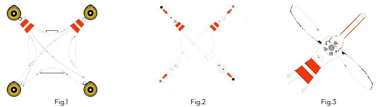
Fitting the Propellers
- (Fig.1) Remove four warning cards from the motors after you read them.
- (Fig.2) Prepare two grey nut propellers and two black nut propellers. Make sure to match the black nut propellers with the correctly marked black dot motors. Tighten the propellers according to the fastening instructions. DO NOT use any thread locker on the threads.
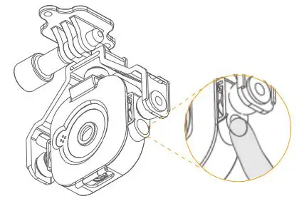
- (Fig.3) Keep motor deadlocked in place with a assistant wrench (or one hand) and remove the propellers
according to the un-fastening instructions.
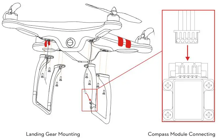
Mounting the Landing Gears s with the Compass Module if Required
If the GPS Mode is desired, you must first mount the landing gear which contains the compass module.
- Prepare aircraft and landing gears.
- Mount the landing gear with compass module to the right part (shown as the following chart); make sure the 5-pin cable is through the hole of the landing gear. Fix the landing gear with screws (M3x6), and then connect the 5-pin cable to the compass module.
- Mount the other landing gear to the left part.
- Fix antennas and 5-pin cable on both landing gears by using the white adhesive tape.
- When flying, please make sure the compass module is stationary and firm.
- If the landing gear with the compass module mount on has been deformed, please replace it with a new one and mount it as the procedures above.
- Compass module is not waterproof, and not anti-oil.
- DO NOT use magnetic screwdriver. Otherwise, keep the screwdriver at least 10cm away from the compass module, to avoid magnetic interference.
Powering on the Transmitter
- Set S1 and S2 switches to the upper most position and all sticks are at mid-point
- Turn power switch to the right end to power on the transmitter.
- There is a power on indicator beep. If the transmitter is set to be CE compliant, then there will be one beep while the FCC compliant version will emit 2 beeps. The power indicator blinks green quickly indicating the transmitter and receiver is linking. Once fully linked, the power indicator will change to a solid green.
Power Indicator Status Information
Powering on the Aircraft
- Place aircraft on the ground
- Open battery compartment cover of the aircraft.
- Put battery into the compartment with the power cord facing outward.
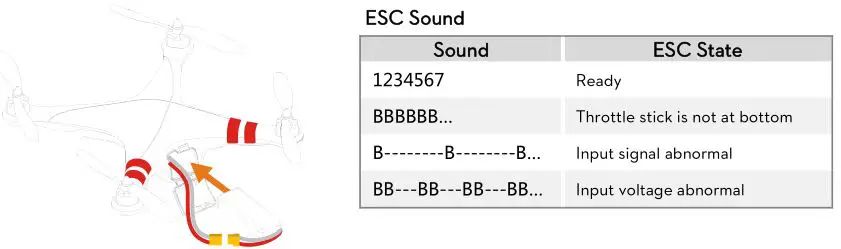
- Connect battery and aircraft by the power lead and make sure the ESCs work properly. (Correct sound)
- Keep all sticks of the transmitter and the aircraft stationary until the system start and self-check has finished
- Put power cable into the battery compartment.
- Close battery compartment cover.
- LED flight indicator may blink Yellow 4 times quickly. Start motor is disabled during LED flight indicator blinking Yellow 4 times quickly, as the system is warming up.
- Contact your dealer if the “System start and self-check LED flashes” are not correct (LED flight indicator appears red in the last four green flashes) in the Step5.
- After the system start and self-checking has finished, if the LED flight indicator blinks Red, Yellow and Green continually, that means the IMU data is abnormal. The PHANTOM FC40 will not work, please connect to the NAZA-M V2 Assistant Software and follow the tips to do operation.
- If it blinks red and yellow lights alternately, that means the compass error is too big, it can be caused by the following three cases. Please connect to the NAZA-M V2 Assistant Software, select the “Tools” tab and follow the tips of the “IMU Calibration” to do operation.
- a) There are ferromagnetic substance around; first make sure that the compass has been calibrated correctly, you can lift the aircraft up (about 1m from the ground), and stay away from the surrounding possible ferromagnetic material object, if there is no red and yellow flashing after lifting it up about 1m from the ground, then it will not affect the flight.
- b) Compass module had been put near a magnet; in this situation please timely replace the compass for a new one, otherwise it will lead to some abnormal action, or even loss of control.
- c) Compass is not properly calibrated; in this situation please calibrate the compass correctly again, please see the “Compass Calibration” section for details.
Compass Calibration
If the compass module is not used, you can skip this step.
The GPS module has a built-in magnetic field sensor for measuring the geomagnetic field, which is not the same in different areas. The GPS module will not work unless the compass module has been connected. Make sure the compass module connection is correct.
Always keep the compass module away from the magnet. If this situation occurs please change the compass module before flying. Otherwise it may damage the compass module and lead the aircraft to work abnormally or even be out of control.
Calibrate the compass before the first flight or when flying in a different area. Make sure to keep away from ferromagnetic substance and other electronic equipment when calibrating or flying. If you keep having calibration failure, it might suggest that there is magnetic interference or other ferromagnetic substance, please avoid flying in this area.
If you have calibration failure or the LED flight indicator blinks red and yellow lights alternately, please connect to the Assistant Software, select the “Tools” tab and follow the tips of the “IMU Calibration” to do operation.
- Quickly switch control mode switch from GPS Mode to ATTI. Mode and back to GPS Mode for 6 to 10 times, The LED flight indicator will turn to constantly yellow.
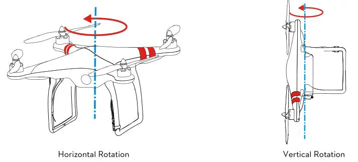
- Rotate your aircraft around the horizontal axis (about 360 o ) until the LED flight indicator changes to constant green, and then go to the next step.
- Hold your aircraft vertically and rotate it (its nose is downward) around the vertical axis (about 360 o ) until the LED flight indicator turns off, meaning the calibration is finished.
- If calibration was successful, calibration mode will exit automatically. If the calibration has failed, the LED flight indicator keeps flashing quickly Red. Switch the control mode switch one time to cancel the calibration, and then restart from step 1.
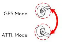
GPS Mode -> ATTI. Mode -> GPS Mode is one time, quickly switch 6 to 10 times
Flight Test
Test Procedure
- If in GPS Mode, place the aircraft in an open space without buildings or trees. Take off the aircraft after 6 or more GPS satellites are found (LED flight indicator blinks red once or no blinking). If in ATTI. Mode, you can skip this step.
- Place aircraft 3 meters away from you and others, to avoid accidental injury.
- Start-up
- Switch on transmitter first, then power on aircraft! Keep the aircraft stationary until the system start and self-check has finished.
- Please wait for system to warm up gradually with LED flight indicator blinks Yellow 4 times quickly. You should not start the motors until the blinking disappears.
- Keep aircraft stationary, and execute any one CSC to start the motors.

- Release yaw, roll and pitch sticks and keep them at neutral position, at the same time raise the throttle stick from the bottom. The motors will stop if you do not push the throttle stick from the bottom within 3 sec and you will need to re-start the motors.
- Keep raising throttle stick until all the motors are working, push the throttle stick to the mid position and then
take-off your aircraft gently, pay attention not to push the stick excessively. - Pay attention to the aircraft movement at any time, and use the sticks to adjust the aircraft’s position. Keep the yaw, roll, pitch and throttle sticks at the mid position to hover the aircraft at desired height.
- Lower aircraft slowly until touch down is achieved. The motors will stop automatically after 3 seconds, or you can repeat the start-up stick command to stop the motors sooner.
- Please always power off aircraft first, and then switch off transmitter after landing.
- At the first motors start, the system will check the sensors Bias and you are asked to keep the aircraft stationary (no need of horizontal level). If you cannot start the motors and the LED flight indicator blinks Green 6 times quickly ( ), it means that the sensor error is too big. Please connect the NAZA-M V2 Assistant Software, enter the “Tools” – > IMU calibration, carry out the basic calibration. Note: after the first successful motors start, this checking will be disabled and it is no need any more to keep the aircraft stationary during starting motors.
- If in GPS Mode, keep the aircraft flying in the open space without obstruction. Pay attention to the GPS satellite status indicator. When the GPS signal has been lost for 3s (LED flight indicator blinks red twice or three times), the system enters ATTI. Mode automatically.
- If battery voltage is too low for flying, the aircraft enters the first level protection with LED flight indicator flashing quickly Red, please land ASAP. Once the aircraft enters the second level protection, the aircraft will drop height automatically.
- If you want to put the PHANTOM FC40 in a car, please keep it away from the speaker, since the
compass module may be magnetized. - DO NOT fly near to ferromagnetic substances, to avoid strong magnetic interference with the GPS.
- It is recommended to land the aircraft slowly, to prevent the aircraft from damage when landing.
- If transmitter indicates low battery alert, please land ASAP. In this condition the transmitter may cause the aircraft to go out of control or even crash.
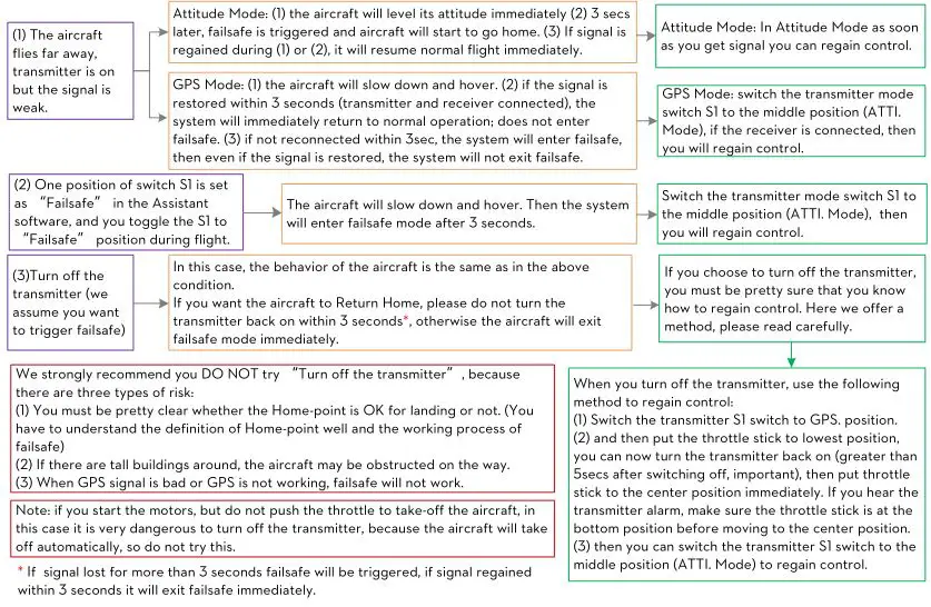
The Failsafe and How to Regain Control
Introduction of Go-Home and Landing
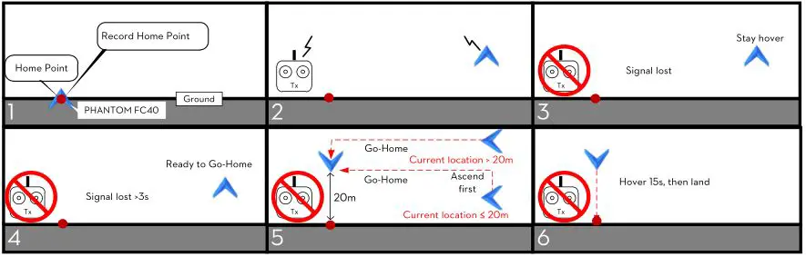
Home-point: Every time you power on, after first motors start, and if 6 or more GPS satellites are found (LED flight indicator blinks red once or no blinking) for 10 seconds, the current position of aircraft will be saved as home-point by controller automatically.
- Please make sure to record the home-point during flight, and clearly know where it is.
- During go-home the nose direction of the aircraft is facing toward the home-point, and the aircraft is flying directly from the current position to the home-point.
The flowchart of failsafe and how to regain control
This section will demonstrate the working logic of failsafe and how to regain control. The following description is effective only when:
- The aircraft is in flight.
- The GPS works normally and signal is GOOD (≥6 satellite, the LED flight indicator blinks a single red light or no red light).
–
–
–
–
Low Voltage Alert
Low Voltage Alert is to indicate that the battery cannot provide enough power for the aircraft, in order to warn you to land the aircraft ASAP. There are both first level and second level protections. You should land your aircraft ASAP to prevent your aircraft from crashing or other harmful consequences!!!
In ATTI. Mode & GPS Mode.
- First level protection has LED flight indicator warning.
- During second level protection the aircraft will land automatically with LED flight indicator warning. Meanwhile the center point of throttle stick will move up slowly to 90% of endpoint, you should land ASAP to prevent your aircraft from crashing! When the center point is at 90% of endpoint, aircraft will still ascend slowly if you continue to pull the throttle stick, and the control of Pitch, Roll and Yaw are the same as before.
![]()
- Configure the FailSafe function in the NAZA-M V2 Assistant Software – – > “Advanced” – – > “F/S” and read the instruction thoroughly and carefully.
- Configure the Low Voltage Alert function in the NAZA-M V2 Assistant Software – – > “Advanced” – -> “Voltage” and read the instruction thoroughly and carefully.
Using the DJI FC40
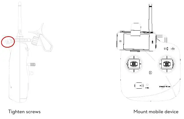
Installing the Mobile Device Mount
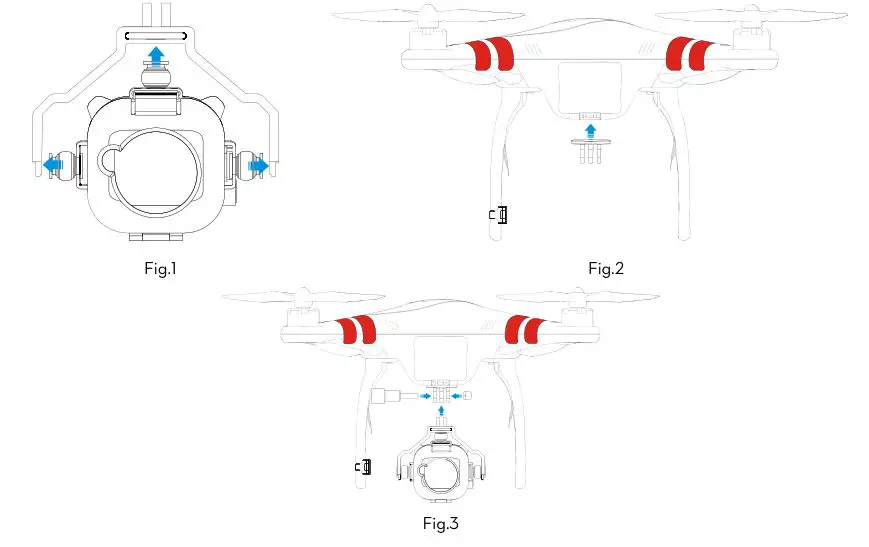
Installing the Camera Mount
- (Fig.1) Attach vibration absorption.
- (Fig.2) Attach connector to aircraft.
- (Fig.3) Tighten screws.
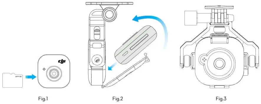
Installing the Camera
- (Fig.1) Plug Micro-SD card into camera.
- (Fig.2) Install camera in camera mount.
- (Fig.3) Make sure camera faces outwards then attach cover.
Camera Functions
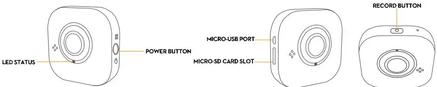
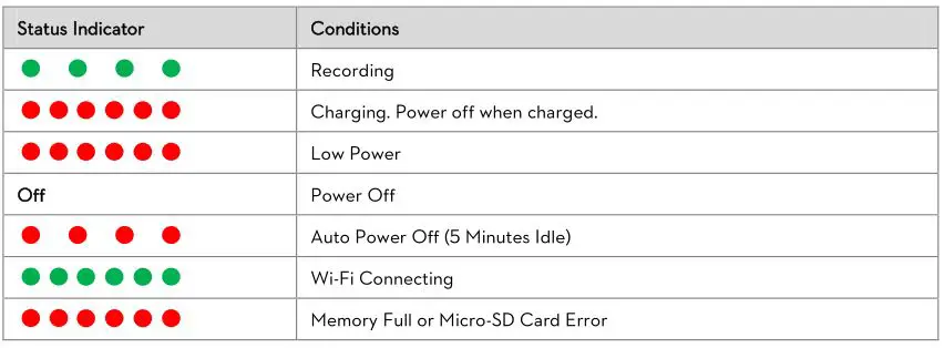
LED Status
Power Button
Power on: Press power button once to turn on camera.
Power off: Press power button for 5 seconds to turn off camera.
See diagram. Press button on camera mount to turn camera on and off.
Micro-USB Port
Use Micro-USB port and Micro-USB cable for charging.
Micro-SD Card Slot
Insert Micro-SD Card.
Remember to remove photos from the card after each flight to ensure space for the next one.
Record Button
Record: Press record button for 3 seconds for video. Press again to stop recording.
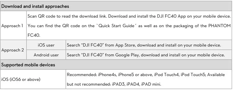
Downloading and Installing the DJI FC40 App

Connecting the DJI FC40 App
To connect a mobile device, follow the instructions below.
- Turn on camera
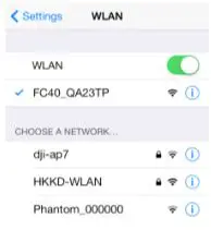
- Enable Wi-Fi on your mobile device. Select FC40_xxxxxx from your Wi-Fi networks.
- Run the DJI FC40 App. This will start a live camera preview. When you see this, everything is ready. Tap “Refresh” to try again if connection fails.
DJI FC40 App Functions
Camera Page
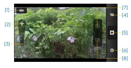
- Tap to return to preview page.
- Tap to zoom in.
- Tap to zoom out.
- Tap to enter album page.
- Camera page.
- Tap to enter settings.
- Tap to take photo.
- Tap to start and stop video recording.
Album Page – Photo
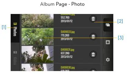
- Tap to view photos.
- Tap to delete item.
- Thumb nail. Tap to view a single photo or move the photo to your mobile device.

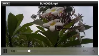
Album Page – Video
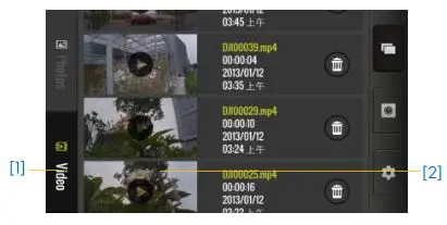
- Tap to view videos.
- Thumb nail. Tap to play a single video or move a video to your mobile device.
Settings Page
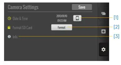
- Set time.
- Tap to format SD card. (Make sure you backup photos before formatting.)
- View version information.
Assistant Software Installation and Configuration
Installing the Driver and Assistant Software
The NAZA-M V2 Assistant Software and the PHANTOM RC Assistant Software are used for advanced adjustments of the PHANTOM FC40. Please follow the steps below to install the Driver and Assistant Software.
- Download
Download driver installer and Assistant Software installer from the DJI website. - Connect
Connect Micro-USB port of PHANTOM FC40 to a USB port of PC via a Micro-USB cable. - Install Driver
Run driver installer and follow the prompts to finish installation. - Install Software
Run Assistant Software installer and follow the prompts to finish installation.
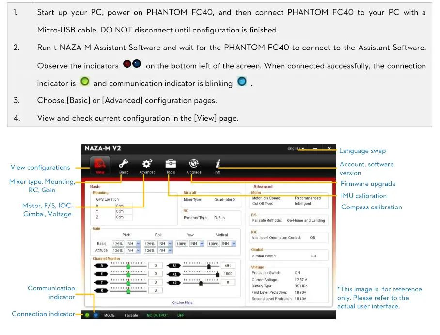
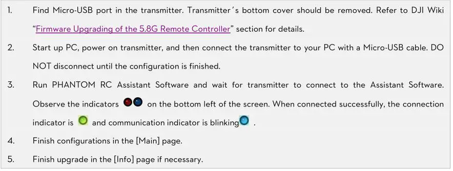
Using the NAZA-M Assistant Software on a PC
Firmware Upgrade of the PHANTOM FC40
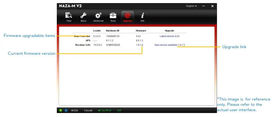
Please follow the procedures to upgrade the firmware; otherwise the PHANTOM FC40 might not work properly.
- An internet connection is required to upgrade the PHANTOM FC40’s firmware.
- Click [Upgrade] icon to check the current firmware version and whether the installed firmware is the latest version. If not, click the relative links to upgrade.
- Be sure to wait until the Assistant Software shows “finished”. Click OK and power cycle the PHANTOM FC40 after 5 seconds. Once completed, the firmware is up to date.
(1) DO NOT power off until the upgrade is finished.
(2) If firmware upgrade failed, the main controller will enter a waiting for firmware upgrade status automatically. If this happens, repeat the above procedures.
PHANTOM RC Assistant Software Description
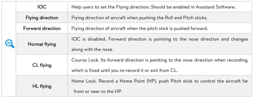
IOC Function
The IOC function should be enabled in the NAZA-M V2 Assistant Software.
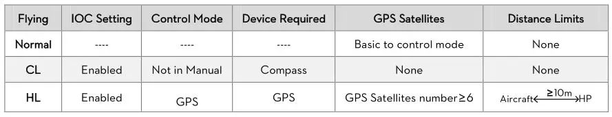
Conditions of IOC function
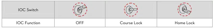
Step 1 IOC switch setting
Please enable the IOC function in Advanced- -> > IOC page of Assistant Software. Then choose a 3-positon switch on the Transmitter to set as IOC switch, which is used to select the different IOC modes and manually record the Forward direction and HP recording.
Below is the IOC switch setting which may be configured in the Assistant Software.
![]()
Above table is for example. The function of the switch position may be reversed since the normal/reversed setting of the switch channel. Toggle the switch and observe the slider position of channel X2 on the Assistant Software screen, the corresponding area should turn blue.
Step 2 Forward direction and HP recording
After you enable the IOC in Assistant Software, the flight control system will record the forward direction and home point automatically after powered on, if the recording conditions are met. You can Manually re-record the forward direction and home point during flying. Read the following table for the recording method details.
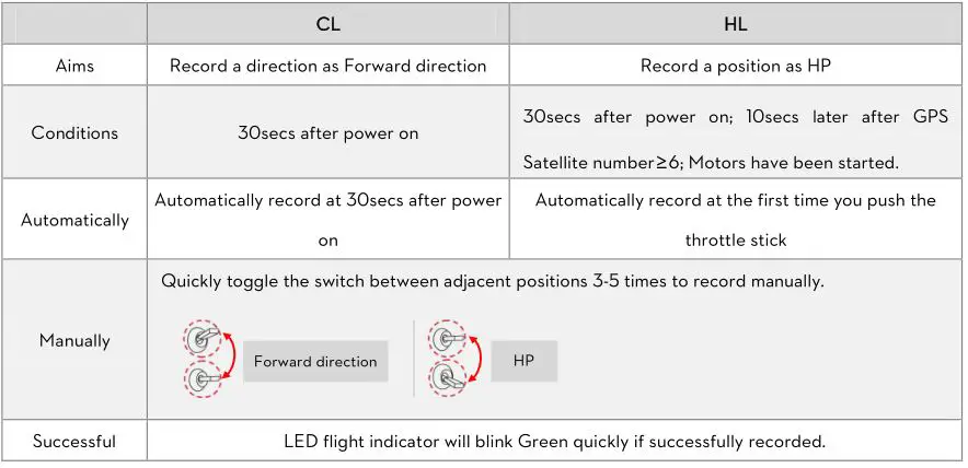
- DO NOT toggle the switch between the OFF and Home Lock positions frequently, which may re-record the Forward Direction.
- HP is used not only in IOC, but also in Failsafe. The flight control system will automatically record the HP even if IOC function is disabled in Assistant Software but Forward direction can be recorded only after IOC is enabled.
Step 3 IOC flying test
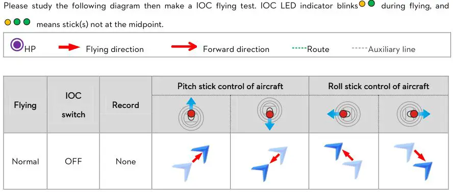
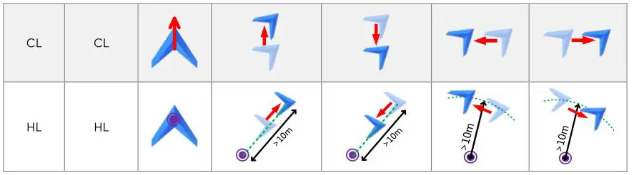
DO NOT toggle the IOC switch frequently in HL flying to avoid re-recording the HP unwittingly.
IOC function is available only when all the required conditions are satisfied. If any condition is omitted the flight control system will exit IOC. Please keep an eye on the LED flight indicator to know the current control mode.
![]()
- It’s recommended to start the HL flight when the aircraft is >10m away from the HP. If starting the HL when the distance between aircraft and HP is less than 10m and it’s the first time you start HL after power on, then the flight control system will only enter HL after flying out of the 10m range.
- During HL flying if one of the following conditions occur, the flight control system will exit HL and enter into CL: the aircraft is within of 10m from HP; the control mode is changed to ATTI; GPS satellite number<6 (The LED flight indicator blinks red twice or three times).
Appendix
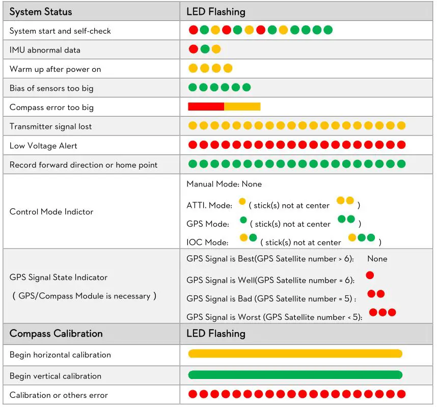
LED Flight Indicator Description
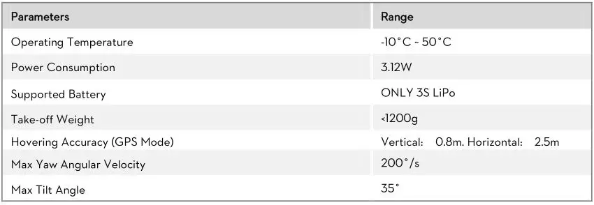
Specifications of the Aircraft
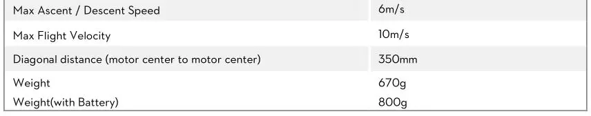
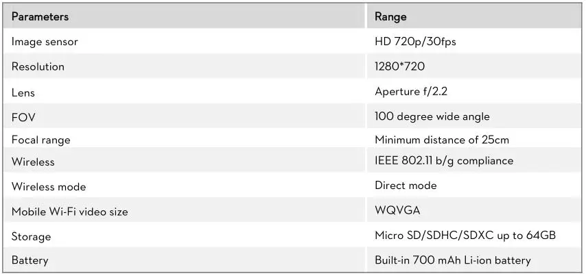
Specifications of the FC40