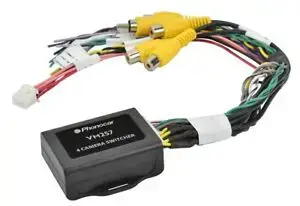

Phonocar 4 Camera Switcher

Connections
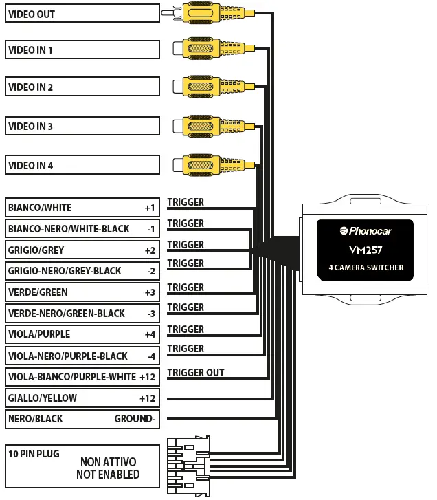
VM257 is a “switcher” for controlling 4 cameras, front, rear and/or additional cameras (e.g. blinkers), working by manually connecting them to their activation “triggers”.
The VM257 also accepts intermittent activation pulses.

Important Notes:
- Connect the yellow wire to Positive or Positive ignition key, depending on the installation to be performed, and the black wire to Negative. The Violet/White wire, upon activation of any trigger, will output 12 volts. (ideal for activating monitors by connecting it to the “Reverse +12” cable) The 10-pin connector in the Switcher is not enabled.
- The video output of the VM257 will always be set by default to input signal 1 when no input trigger is activated. This input is ideal for connecting the rear camera (reverse).
- The inputs of the VM257 have priority in descending numerical order. E.g.: If input 3 or 4 is activated, a lower number input (e.g. input 2) is activated. Input 2 will take priority over the higher numbered input.
- The Input triggers can accept either pulsed or constant input, making them ideal for connecting to a turn signal as a trigger.
- The reverse trigger output will provide a 150 mA 12v (+) trigger, while any of the input triggers activated.
- Upon deactivation of the last positive or are negative trigger, the last video input source and reverse trigger output will remain active for an additional 3 seconds. (Not applicable when used with a BCI-, RP4.2- or RP5.2- interface).
- If the video quality after installation of the module is poor, make sure that all RCA connections have been made correctly.
- Positive input triggers accept input voltages in the range of 2v to 12v.
Note : If there is no TRIGGER, the priority will be “VIDEO IN 1” but there will be no +12V on the violet/black monitor cable.
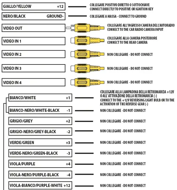
EXAMPLE 1: CONNECTION WITH REAR CAMERA FOR REVERSING

NOTE Connect either the positive trigger or the negative trigger, not both at the same time.
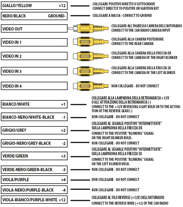
EXAMPLE 2: CONNECTION OF 3 CAMERAS (2 CAMERAS ON THE BLINKERS)

NOTE If you activate the 4 blinkers, two triggers are activated (2/3) and on the display you will have the triggered camera with the lowest number, in this case the n.° 2 “RIGHT BLINKER”.
