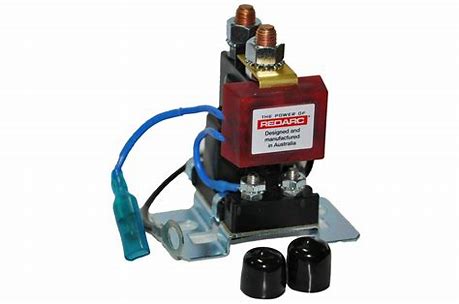
THE SMART START® SBI
The Smart Start® SBI is a microprocessor-controlled Smart Battery Isolator. The Smart Start® SBI is designed specifi cally for use in multi battery applications as a solenoid priority system to protect the start battery from being excessively discharged by auxiliary loads, whilst still allowing the auxiliary battery to supply non essential loads. Put simply, once the start battery has had some charge from the alternator, the Smart Start® SBI will connect an auxiliary battery to the charge circuit. Similarly, if the start battery voltage drops too low, the Smart Start® SBI will disconnect any auxiliary batteries or loads from the start battery to conserve charge.
SPECIFICATIONS
| Part Number | SBI12 (D)* | SBI24 (D)* | SBI212 (D)* | SBI224 (D)* |
| System Voltage | 12V | 24V | 12V | 24V |
| ON Volts | 13.2V | 26.4V | 13.2V | 26.4V |
| OFF Volts | 12.7V | 25.4V | 12.7V | 25.4V |
| Turn ON Delay | 5 sec | 5 sec | 5 sec | 5 sec |
| Turn OFF Delay | 10 sec | 10 sec | 10 sec | 10 sec |
| Max. Cont. Current | 100 Amps | 100 Amps | 200 Amps | 200 Amps |
| Max. Inrush Current | 400 Amps | 400 Amps | 600 Amps | 600 Amps |
| Standby Current | < 5mA | < 5mA | < 5mA | < 5mA |
| Dimensions | 75x70x80mm | 90x95x100mm | ||
| Weight | 200g | 600g | ||
| Warranty | 2 years | |||
| Standards | CE, C-Tick, AS/NZS CISPR11:2004 | |||
*D indicates “Dual Sensing” which is described on page 4.
CABLE SIZE, CIRCUIT BREAKER(CB)/FUSE SIZE AND STUD TORQUE CHART
| Model | Wire Length | Start Feature with Pushbutton Override | No Override | Main Stud Torque | ||
| CB or Fuse | Wire | CB or Fuse | Wire | |||
| SBI12/ SBI24 | Up to 3m | 100 Amps | 19mm² (4B&S) | 60 Amps | 8mm² (8B&S) | 5 – 6.2 Nm |
| 3m to 6m | 100 Amps | 32mm² (2B&S) | 60 Amps | 13mm² (6B&S) | 5 – 6.2 Nm | |
| SBI212/ SBI224 | Up to 3m | 200 Amps | 32mm² (2B&S) | 120 Amps | 19mm² (4B&S) | 6.5Nm max |
| 3m to 6m | 200 Amps | 40mm² (1B&S) | 120 Amps | 25mm² (3B&S) | 6.5Nm max | |
INSTALLATION INSTRUCTIONS
- Mount the Smart Start® SBI securely in a convenient location near the start battery bank. Do not mount in direct engine heat.
- Install in the order described below:
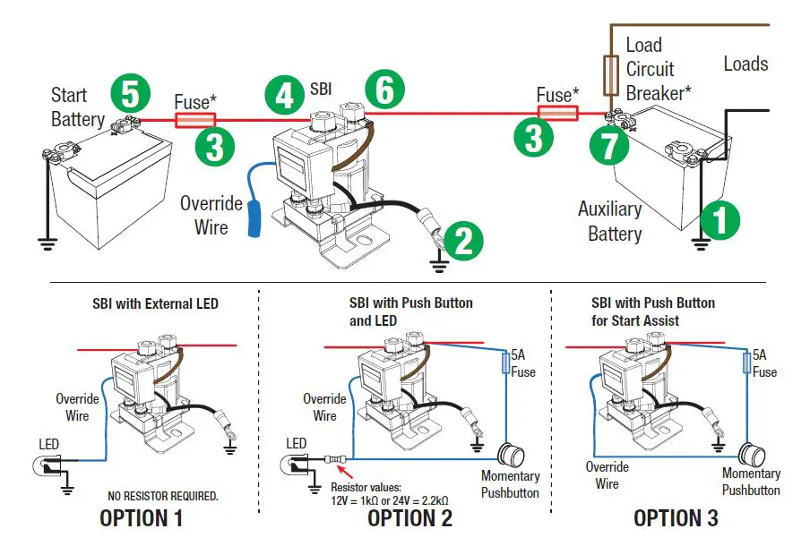
- Make sure the auxiliary battery negative is properly grounded to the vehicle chassis (1)
- Ground Connection. Connect the Smart Start® SBI ground terminal to chassis ground. Remove any paint to ensure a good ground connection. Note: A good ground will ensure correct switching voltage. (2)
- Select correct Circuit Breaker/Fuse sizes and install at battery end of both positive cables (3)
- Connect the cables in the order shown on the next page (4,5,6,7)
- LED Connections (optional). Connect a wire from the Blue wire of the Smart Start® SBI to the positive end of an indicator LED (15mA limited current draw) or LED/resistor combination mounted on the dash as specifi ed in the diagram on page 3.
- Start Assist Feature (optional). Connect a wire from the Blue wire of the Smart Start® SBI to one terminal of a momentary push button switch. Connect the other terminal of the momentary push button switch to the auxiliary battery supply. To manually operate the Smart Start® SBI, hold the momentary push button switch and the Smart Start® SBI will manually operate until the switch is released. After about 10 seconds start the vehicle with the button still held on.
- Checking the Operation: The Smart Start® SBI should now be operational. Start the vehicle or apply a charge to the start battery. Once the start battery voltage rises to the ‘ON Volts’ level the Smart Start® SBI will activate, you will hear the solenoid click and see the LED illuminate. Now turn off the vehicle or remove the charger from the start battery. The Smart Start® SBI will disconnect the auxiliary battery once the voltage on the start battery drops to the OFF Volts level, you will hear the solenoid click and the LED will go out.
Note: The amount of time it takes for the battery voltage to drop low enough for the solenoid to turn off will vary due to battery condition, age and state of charge. (For a new, fully charged battery, it may take days).
Note: See table on page 1 for specifi c voltage levels.
NOTE: As per above, the LED may stay ON for a period of time after the vehicle is turned OFF.
RECOMMENDED FUSES
REDARC recommends using MIDI fuses along with a quality fuse holder to match. The diagram below shows the construction of a MIDI fuse installation (cables not included).
REDARC MIDI fuse kits containing 4x fuses and 2x fuse
holders along with the required nuts are available from
most Auto Electrical outlets.
Part Numbers:
FK60 60A fuse kit
FK100 100A fuse kit
STANDARD WIRING DIAGRAMS
- Ensure the adequately sized cable is used as per the chart on page 1.
- Ensure the auxiliary battery is properly grounded to a common chassis earth point.
- Ensure the SBI ground wire is making good contact with the chassis ground point.
- When using fuses make sure that the fuse makes a good low resistance connection.
- Fuse/Circuit Breaker ratings are dependent on the type of installation and the size of the loads, refer to chart on page 1.
DUAL SENSING SMART START® SBI
Dual Sensing Smart Start® SBIs or ‘D’ Series SBIs monitor both the start battery and the auxiliary. If the unit detects that either battery has exceeded 13.2V the isolator will be connected. The benefi t of the dual control enables the user to charge the main battery from a solar panel or battery charger on the auxiliary battery. The SBI12D has the added feature of allowing charge both ways.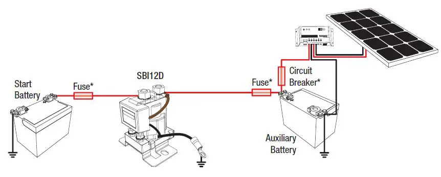
- When using fuses make sure that the fuse makes a good low resistance connection.
Circuit Breaker/Fuse ratings are dependent on the type of installation and the size of the loads.
FAULT INDICATION
NOTE: The LED may stay ON for a period after the vehicle is turned OFF. This in NOT a fault. Should a fault occur, the Smart Start® SBI is set to notify the operator of the fault. The LED will fl ash repeatedly with the following sequences:
| CODE 1 | 2 Flashes | Over-Voltage |
| CODE 2 | 3 Flashes | Voltage Drop or Excessive Current Draw Fault |
FAULT CODE 1: 2 Flashes (Over-Voltage Detection)
If the batteries connected to either terminal of the Smart Start® SBI should rise above 15.5 Volts (31 Volts on a 24 volt system), the Smart Start® will:
- Disconnect, if connected, to prevent the source of over-voltage reaching the other battery
- Flash the LED 2 times for 20 seconds, then reassess the fault condition, continuing until the fault is cleared.
FAULT CODE 2: 3 Flashes (Voltage Drop / Excessive Current Draw)
If the Smart Start® SBI detects a voltage drop across its contacts of greater than 1 Volt for more than ½ second then the unit will:
- Immediately protect itself by disconnecting the auxiliary battery; and
- Flash the LED 3 times for 20 seconds, then reassess the presence of a fault, continuing until the fault is cleared.
FREQUENTLY ASKED QUESTIONS
- Question: Why does the LED stay on after the vehicle is turned off?
Answer: The LED stays on (indicating the Smart Start® is on & the batteries are linked) until the voltage drops to 12.7V (25.4V for SBI24). This can take a few minutes to many hours, depending on size & state of charge of the batteries as well as load on the batteries. To test this feature of the Smart Start®, with the engine turned off, turn the headlights on and the Smart Start® LED should go out, this may take a couple of minutes. - Question: Is the unit protected against voltage spikes?
Answer: Yes, the Smart Start® SBI incorporates a number of spike protection components specifi cally designed to reduce the risk of damaging the unit. The Smart Start® SBI is also designed to prevent any spikes generated by the solenoid coil from affecting any vehicle equipment. - Question: What does the red LED indicate?
Answer: The red LED indicates the solenoid is activated and both batteries are connected together and therefore are both being charged simultaneously. A fl ashing red LED during operation indicates a fault. See Fault Indication page 4. - Question: Can the voltage limits and time delay settings be changed?
Answer: Yes! Both upper and lower voltage limits & on and off times can be changed. However, this needs to be done at the time of manufacture and will incur a relatively minor cost. - Question: We are experiencing repetitive switching of our Smart Start® SBI. What could be causing this?
Answer: This can occur for one of two reasons. Firstly, switching a poorly charged second battery into the system loads the voltage at the Smart Start® SBI to below its lower voltage limit, which will cause the Smart Start® SBI to switch back off. Secondly, voltage drop due to cable length (Smart Start® SBI mounted too far from start battery) can cause the voltage at the start terminal on the Smart Start® SBI to be lower than at the start battery, which can also cause the unit to switch off. Voltage seen by the Smart Start® SBI will now rise again until the Smart Start® SBI switches back on. This switching will continue until the cause of voltage drop is removed. On and Off Time delays are built into the product to avoid the solenoid contacts chattering in this scenario. - Question: Can I use the Smart Start® SBI to control a load (e.g. fridge) without using an auxiliary battery?
Answer: Yes. The voltage monitoring is done on the start battery side of the unit. If a load is connected on the auxiliary side instead of a battery, the unit will still operate when the start battery is charged, providing power to your load. - Question: Does the internal LED illuminate when I use the external override switch?
Answer: Yes. - Question: Can I use my Smart Start® SBI to winch off both batteries?
Answer: Yes. We recommend that the Smart Start® SBI be wired so it automatically connects both batteries when the winch is turned on, through use of the Start Assist feature on the override wire. We also recommend the use of our 200Amp Smart Start® SBI for this application. - Question: Can I use the Smart Start® SBI on a positive chassis vehicle?
Answer: Yes. Please contact REDARC for further information.
WARNING and SAFETY INSTRUCTIONS
SAVE THESE INSTRUCTIONS – This manual contains IMPORTANT SAFETY INSTRUCTIONS for the Smart Start® SBI battery isolator.
DO NOT OPERATE THE ISOLATOR UNLESS YOU HAVE READ AND UNDERSTOOD THIS MANUAL AND THE ISOLATOR IS INSTALLED AS PER THESE INSTALLATION INSTRUCTIONS.
WARNING: RISK OF EXPLOSIVE GASES:
IN THE VICINITY OF A LEAD-ACID BATTERY IS DANGEROUS. BATTERIES GENERATE EXPLOSIVE GASES DURING NORMAL OPERATION. FOR THIS REASON, IT IS OF UTMOST IMPORTANCE THAT YOU FOLLOW THE INSTRUCTIONS EACH TIME YOU USE THE CHARGER.
- Only use the Battery Isolator for charging Standard Automotive Lead Acid, Calcium Content, Gel, AGM, SLI or Deep Cycle type batteries.
- Do NOT use the Battery Isolator to charge:
- Dry-cell batteries are commonly used with home appliances.
- Batteries with voltage ratings other than 12V (or 24V for 24V unit)
- Non-rechargeable batteries
- A frozen Battery. Thaw completely before attempting to charge.
Charging batteries under these circumstances may cause the battery to explode or rupture during charging and cause injury to persons, damage to the Battery Isolator and/or property.
- NEVER smoke or allow a spark or flame in the vicinity of the battery or engine. This may cause the battery to explode.
- Be extra cautious so as to reduce the risk of dropping a metal tool onto a vehicle battery. Doing so might cause the battery to spark or might short-circuit the battery or other electrical parts that may cause an explosion.
- Remove personal metal items such as rings, bracelets, necklaces, and watches when working with a lead-acid battery. A lead-acid battery can produce a short-circuit current high enough to weld a ring or the like to metal, causing a severe burn.
- A SPARK NEAR A BATTERY MAY CAUSE THE BATTERY TO EXPLODE. TO REDUCE THE RISK OF A SPARK NEAR A BATTERY WHEN CONNECTING THE BATTERY INSTALLED IN A VEHICLE TO THE ISOLATOR, ALWAYS DO THE FOLLOWING:
- Position DC cords to reduce the risk of damage by the vehicle hood, door, or moving engine part.
- Stay clear of fan blades, belts, pulleys and other parts that can cause injury to persons.
- Check the polarity of battery posts. The POSITIVE (POS, P, +) battery post usually has a larger diameter than the NEGATIVE (NEG, N, -) battery post however you should always check the label on the battery.
- Determine which post of the battery is grounded (connected) to the chassis. If the negative post is grounded to the chassis (as in most vehicles), see (e). If the positive the post is grounded to the chassis see (f).
- For a negative-grounded vehicle, connect the POSITIVE (RED) terminals from the Battery Isolator to the POSITIVE (POS, P, +) ungrounded post of each battery. Connect the NEGATIVE (BLACK) lead to a metal part of the frame or the vehicle chassis, away from the battery. Do not connect the connector to the carburetor or fuel lines.
- For positive-grounded vehicles, connect the NEGATIVE (BLACK) lead from the Battery Isolator to the NEGATIVE (NEG, N, -) ungrounded post of the battery. Connect the POSITIVE (RED) terminals to to the POSITIVE (POS, P, +) post of each battery. Do not connect the connect to the carburetor, fuel lines, or sheet-metal body parts. Only the start battery should be connected to the chassis.
- PERSONAL SAFETY PRECAUTIONS
To assist with safely working with Batteries:- Consider having someone close by to come to your aid when you are working with the Battery.
- Have plenty of fresh water and soap nearby in case battery acid contacts skin, clothing, or eyes.
- Wear complete eye protection and clothing protection. Avoid touching eyes while working near a battery.
- If battery acid contacts your skin or clothing, remove the affected clothing and wash the affected area of your skin immediately with soap and water. If battery acid enters your eye, immediately fl ood the eye with running cold water for at least 10 minutes and seek medical assistance immediately.|
NOTICE
-
- It is recommended that start and auxiliary batteries be of similar chemical characteristics when charging via the Smart Start® SBI.
- The Smart Start® SBI will achieve best results when proper battery maintenance is regularly performed. This includes but is not limited to checking water and specifi c gravity levels of the battery. Refer to the battery manufacturer manual for more details.
- Fuses or Circuit breakers of appropriate rating must be installed to protect the vehicle system. Please refer to the installation instructions on page 2 for specifi c instructions on where to install Fuses or Circuit breakers and the table on page 1 for appropriate Fuse or Circuit Breaker ratings.
- Fuses must be installed as close as possible to the battery.
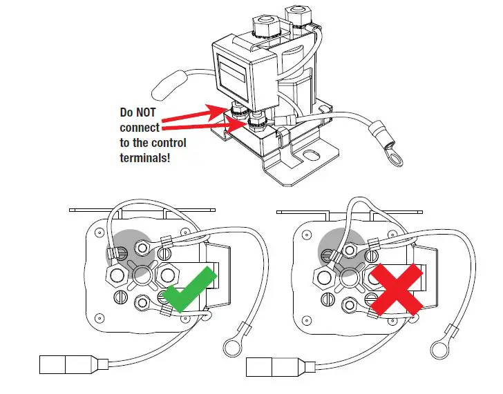
- IMPORTANT! Do NOT make any connections to the control terminals found on the front of the unit (100A models) or the top of the unit (200A models). Ensure that connections are not accidentally bridged between terminals whilst tightening. Connecting to the control terminals on the front of the SBI may cause damage to the unit and/or equipment connected to it. Connecting to the control terminals will void the warranty of the unit.
TWO YEAR PRODUCT WARRANTY
Over the last three Dover the last three decades our companecades our company has established a reputed reputation action as the po power conversion specialist.on specialist.
A 10A 100% 0% AustraAustralian-olian-owned owned companompanyy,, we ha have met the needs of customers in transpire met the needs of customers in the transport and other industries through exciting, ort and other industries through exciting, inn inovaovattive the thinking. king. We believe in tota belief in total customer sal customer satisfaction and practice THE Satisfaction and practice this by offering our customers: by offering our customers:
- Technical advice free of technical advice free of jargon and free of chargeargon and free of charge
- Prompt turnaround of orders throughout f orders throughout Australia Australia and globally and globally
- Frienriendlydly,, person personalized, realized, profess professional personal service and provide and product support duct support
In the unlikely event that a technical issue arises with a Redarc product,s with a Redarc product, customers are encouraged to initially ged to initially contact the Recontact the Redadarc rc technical Support Support team on (08)team on (08) 8322 4848 8322 4848 or r poower@[email protected].aurc.com.au for prom for prompt and effipt and effi ancient diet diagnosis and prognosis and product support. product support.
Our goods come with guarantees tOur goods come with guarantees that cannot be excluded under the hat cannot be excluded under the Australian Australian Consumer Lawnsumer Law.. you are entitled to ou are entitled to a replacement ora replacement or refund for a major failure and compensation for and compensation for any other reasonably foreseeable loss or damage. seeable loss or damage. you are also entitled to have the goods repaired or replaced if the goods fail repaired or replaced if the goods fail to be of acceptable quality and the failure does not and the failure does not amount to an amount to a major failure. major failure.
The be benefienefi ts of this Warranty are in addition to other rights and remedies warranty are in addition to other rights and remedies available at law in respect of the Products and shall available at law in respect of the Products and shall not derogate from any applicable mandatory stay statutory provisions or provisions or rights under the Australian Australian Consumer Lawn summer Law..
Redarc Electronics PRedarc Electronics Pty Ltd atf the Redarc ty Ltd atf the Redarc TTrust trading as Rerust trading as Redarc Electronics (“darc Electronics (“ReRedardarcc”) offers a warranty in respect of its Product”) offers a warranty in respect of its Products where the Products are purchased from ans where the Products are purchased from an authorized distributor or reauthorized distributor or reseller of Redarc by a person (“ller of Redarc by a person (“Purchaser”),), on the terms on the terms and conditions, and conditions, and forth and for the duration,e duration, outlined below in this document (“ this document (Warranty”)
- In this Warranty, the term Products means:
- all products manufactured or supplied by Redarc (excluding its solar products which are covered by Redarc’s Solar Product Warranty); and
- any component of or accessory for any product in clause 1.1 manufactured or supplied by Redarc.
Offer and duration of product warranties
- Redarc warrants that its Products will be free, under normal application, installation, use and service conditions, from defects in materials and workmanship affecting normal use, for 2 years from the date of purchase (Warranty Period).
- Where a Product malfunctions or becomes inoperative during the Warranty Period, due to a defect in materials or workmanship, as determined by Redarc, then subject to further rights conferred by the Australian Consumer Law on the Purchaser, Redarc will, in the exercise of its sole discretion, either:
- replace the defective Product; or provide a refund to the Purchaser for the purchase price paid for the defective Product, without charge to the Purchaser.
- The warranty given by Redarc in clause 3 covers the reasonable costs of delivery and installation of any repaired or replaced Products or components of Products
to the Purchaser’s usual residential address notifi ed to Redarc, together with the reasonable costs of removal and return of any Products determined by Redarc to be defective. - If the Purchaser incurs expenses of the nature referred to in clause 4 in the context of making a claim pursuant to this Warranty that is accepted by Redarc, the Purchaser will be entitled to claim for reimbursement of those expenses which Redarc determines, in the exercise of its sole discretion, to be reasonably incurred, provided that the claim is notifi ed to Redarc in writing at the postal address or email address specifi ed in clause 21 and includes:
- details of the relevant expenses incurred by the Purchaser; and
- proof of the relevant expenses having been incurred by the Purchaser.
Exclusions and limitations - This Warranty will not apply to, or include any defect, damage, fault, failure or malfunction of a Product, which Redarc determines, in the exercise of its sole discretion, to be due to:
- normal wear and tear or exposure to weather conditions over time;
- accident, misuse, abuse, negligence, vandalism, alteration or modifi cation;
- non-observance of any of the instructions supplied by Redarc, including instructions concerning installation, confi during, connecting, commissioning, use or application of the Product, including without limitation choice of location;
- failure to ensure proper maintenance of the Product strictly in accordance with Redarc’s instructions or failure to ensure proper maintenance of any associated equipment or machinery;
- repairs to the Product that are not strictly in accordance with Redarc’s instructions;
- installation, repairs or maintenance of the Product by, or under the supervision of, a person who is not a qualifi ed auto electrician or technician, or if non-genuine or non-approved parts have been fi tted;
- faulty power supply, power failure, electrical spikes or surges, lightning, fl good, storm, hail, extreme heat, fi re or another occurrence outside the control of Redarc;
- use other than for any reasonable purpose for which the Product was manufactured;
- any indirect or incidental damage of whatever nature outside the control of Redarc.
- Warranty claims in respect of a Product must be made in writing to Redarc at the postal address or email address specifi ed in clause 21 within the Warranty Period. Such claims must include the following:
- details of the alleged defect or fault and the circumstances surrounding the defect or fault;
- evidence of the claim, including photographs of the Product (where the subject of the claim is capable of being photographed);
- the serial number of the Product, specifi ed on the label affi xed to the Product; and
- proof of purchase documentation for the Product from an authorized distributor or reseller of Redarc, which clearly shows the date and place of purchase. The return of any Products without the prior written instructions of Redarc will not be accepted by Redarc.
- Without limiting any other clause in this Warranty, Redarc has the right to reject any Warranty claim made by a Purchaser pursuant to this Warranty where:
- the Purchaser does not notify Redarc in writing of a Warranty claim within the Warranty Period;
- the Purchaser does not notify Redarc in writing of a Warranty claim within 1 month of becoming aware of the relevant circumstances giving rise to the claim, so that any further problems with the Product are minimized;
- the serial number of the Product has been altered, removed or made illegible without the written authority of Redarc;
- the Purchaser is unable to provide proof of purchase documentation in accordance with clause 7.4 or evidence that the Product was properly installed and removed (if relevant), and that proper maintenance has been performed on the Product, by, or under the supervision of, a qualifi ed auto electrician or technician, in accordance with the instructions of Redarc.
- If the Product is found to be working satisfactorily on return to Redarc or upon investigation by Redarc, the Purchaser must pay Redarc’s reasonable costs of testing and investigating the Product in addition to shipping and transportation charges. Where Redarc is in possession of the Product, the Product will be returned to the Purchaser on receipt of the amount charged.
- Any replaced Products or components of Products shall become the property of Redarc.
- Redarc may, in the exercise of its sole discretion, deliver another type of Product or component of a Product (different in size, color, shape, weight, brand and/or other specifi cations) in fulfi lling its obligations under this Warranty, in the event that Redarc has discontinued manufacturing or supplying the relevant Product or component at the time of the Warranty claim, or where such Product or component is superior to that originally purchased by the Purchaser.
Other conditions of Warranty - If the Purchaser acquired a Product for the purpose of resupply, then this Warranty shall not apply to that Product.
- In particular, the sale of a Product via an online auction, online store or another internet website by a party that is not an authorized distributor or reseller of the Product will be deemed to be a resupply within the meaning of the Australian Consumer Law and will render this Warranty void, as Redarc has no control over the storage, handling, quality or safety of Products sold by such persons.
- A Purchaser shall only be entitled to the benefi t of this Warranty after all amounts owing in respect of the Product have been paid.
- While Redarc warrants that the Products will be free from defects in materials and workmanship in the circumstances set out in this Warranty, to the maximum extent permitted by law Redarc does not warrant that the operation of the Products will be uninterrupted or error-free.
- To the maximum extent permitted by law, Redarc’s determination of the existence of any defect and the cause of any defect will be conclusive.
- Spare parts or materials for the Products are guaranteed to be available for a period of at least 2 years after purchase of the Products.
- The agents, offi cers and employees of any distributor or reseller of the Products and of Redarc are not authorized to vary or extend the terms of this Warranty.
- Redarc shall not be responsible or liable to the Customer or any third party in connection with any non-performance or delay in performance of any terms and conditions of this Warranty, due to acts of God, war, riots, strikes, warlike conditions, plague or another epidemic, fi re, fl ood, blizzard, hurricane, changes of public policies, terrorism and other events which are beyond the control of Redarc. In such circumstances, Redarc may suspend the performance of this Warranty without liability for the period of the delay reasonably attributable to such causes.
- If a clause or part of a clause in this Warranty can be read in a way that makes it illegal, unenforceable or invalid, but can also be read in a way that makes it legal, enforceable and valid, it must be read in the latter way. If any clause or part of a clause in this Warranty is illegal, unenforceable or invalid, that clause or part is to be treated as removed from this Warranty, but the rest of this Warranty is not affected.
Redarc’s contact details
21. Redarc’s contact details for the sending of Warranty claims under this Warranty are:
Redarc Electronics Pty Ltd
23 Brodie Road (North), Lonsdale SA 5160
Email: [email protected]
Telephone: +61 8 8322 4848
Free technical assistance!
For product and technical support contact your regional distributor, call our head offi ce between 8:00 am to 5:30 pm Australian Central Standard Time, Monday to Friday or send an email using the regional specifi c details outlined below.
For specifi c USA Warranty terms please visit…
www.redarcelectronics.com