 http://register.ryobitools.com
OPERATOR’S MANUAL
40 VOLT BRUSHLESS GRASS TRIMMER
SIN ESCOBILLAS
RY402011
WARNING: To reduce the risk of injury, the user must read and understand the operator’s manual before using this product.
SAVE THIS MANUAL FOR FUTURE REFERENCE
See this fold-out section for all the figures referenced in the operator’s manual.
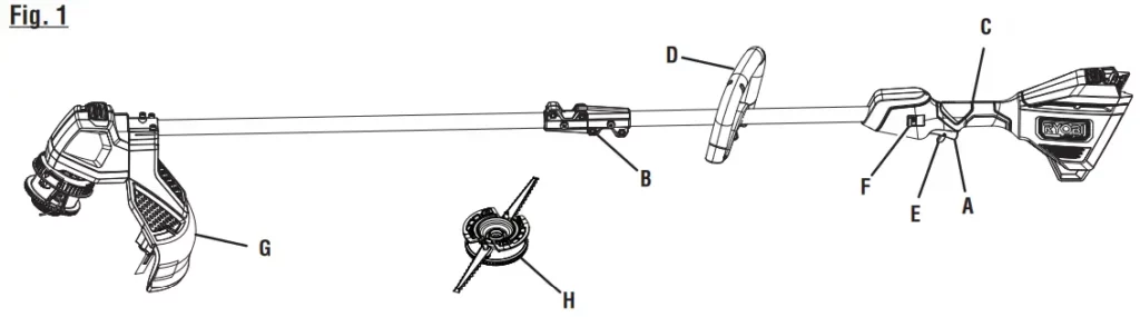
Fig. 1
| A – Switch trigger B – Coupler C – Rear handle D – Front handle |
E – Trigger lock-out F – Speed switch G – Grass deflector H – Fixed line |

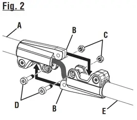
| Fig. 2 A – Upper shaft B – Connectors C – Nuts D – Bolts E – Lower shaft |
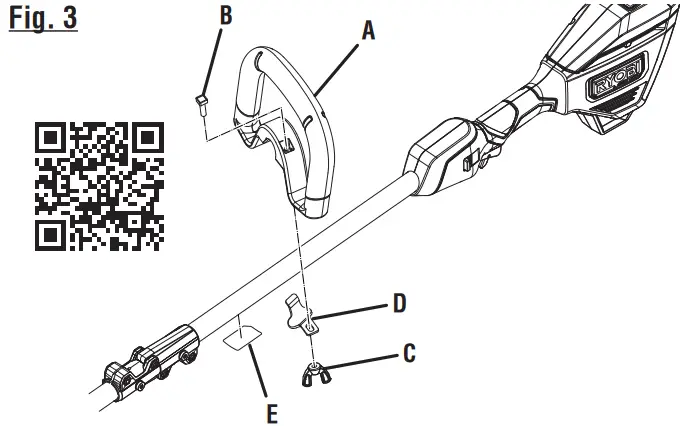
Fig. 3 A – Front handle B – Bolt C – Wing nut D – Bracket E – QR code label |
 |
 |
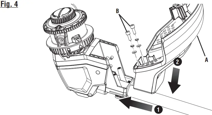
| Fig. 4 A – Grass deflector B – Screws |
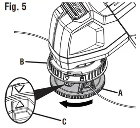
Fig. 5 A – Lower bump feed trimmer head housing B – Upper housing C – Arrows aligned |
 |
 |
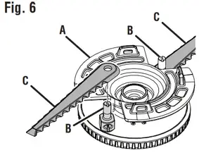
| Fig. 6 A – Fixed line/blade housing B – Posts C – Blades |
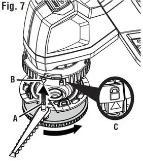
Fig. 7 A – Posts B – Arrows C – Locked position |
 |
 |
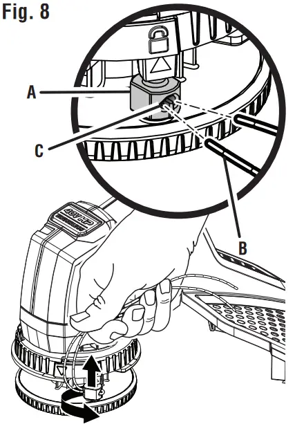
| Fig. 8 A – Posts B – Pre-cut line C – Eyelet |
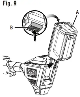
Fig. 9 A – Battery pack B – Latch |
 |
 |
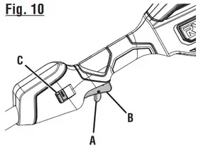
| Fig. 10 A – Trigger lock-out B – Switch trigger C – Speed switch |
Fig. 11 PROPER TRIMMER OPERATING POSITION |
 |
 |
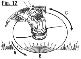
| Fig. 12 A – Direction of rotation B – Best cutting area C – Dangerous cutting area |
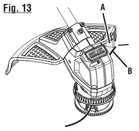
Fig. 13 A-Line cut-off blade B – Line |
 |
 |
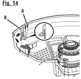
| Fig. 14 A – Screw B – Line cut-off blade |
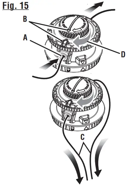
Fig. 15 A – Eyelet B – Arrows C – Pull lines D – Rotate the bump knob |
 |
 |
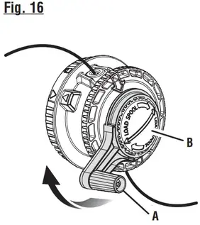
| Fig. 16 A – SPEED WINDER B – Bump knob |
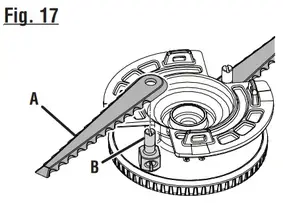
Fig. 17 A – Blade B – Post |
 |
 |
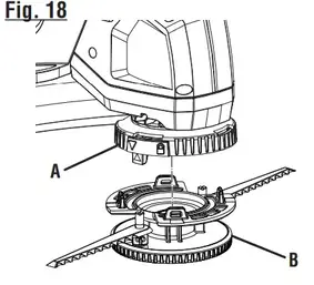
| Fig. 18 A – Upper housing B – Lower housing |
Fig. 19 A – Upper string head housing B – Tabs C – Lower string head housing D – Spool E – Bump knob F – Spool slots G – Knob ribs |
 |
 |
GENERAL POWER TOOL SAFETY WARNINGS
WARNING!
Read all safety warnings, instructions, illustrations, and specifications provided with this power tool. Failure to follow all instructions listed below may result in electric shock, fire, and/or serious injury. Save all warnings and instructions for future reference. The term “power tool” in the warnings refers to your mains-operated (corded) power tool or battery-operated (cordless) power tool.
WORK AREA SAFETY
- Keep the work area clean and well-lit. Cluttered or dark areas invite accidents.
- Do not operate power tools in explosive atmospheres, such as in the presence of flammable liquids, gases, or dust. Power tools create sparks that may ignite dust or fumes.
- Keep children and bystanders away while operating a power tool. Distractions can cause you to lose control.
ELECTRICAL SAFETY
- Power tool plugs must match the outlet. Never modify the plug in any way. Do not use any adapter plugs with earthed (grounded) power tools. Unmodified plugs and matching outlets will reduce risk of electric shock.
- Avoid body contact with earthed or grounded surfaces such as pipes, radiators, ranges, and refrigerators. There is an increased risk of electric shock if your body is earthed or grounded.
- Do not expose power tools to rain or wet conditions. Water entering a power tool will increase the risk of electric shock.
- Do not abuse the cord. Never use the cord for carrying, pulling, or unplugging the power tool. Keep cord away from heat, oil, sharp edges, or moving parts. Damaged or entangled cords increase the risk of electric shock.
- When operating a power tool outdoors, use an extension cord suitable for outdoor use. The use of a cord suitable for outdoor use reduces the risk of electric shock.
- If operating a power tool in a damp location is unavoidable, use a ground fault circuit interrupter (GFCI) protected supply. The use of a GFCI reduces the risk of electric shock.
PERSONAL SAFETY
- Stay alert, watch what you are doing, and use common sense when operating a power tool. Do not use a power tool while you are tired or under the influence of drugs, alcohol, or medication. A moment of inattention while operating power tools may result in serious personal injury.
- Use personal protective equipment. Always wear eye protection. Protective equipment such as dust masks, nonskid safety shoes, hard hats, or hearing protection used for
appropriate conditions will reduce personal injuries. - Prevent unintentional starting. Ensure the switch is in the off-position before connecting to a power source and/or battery pack, picking up or carrying the tool. Carrying power tools with your finger on the switch or energizing power tools that have the switch on invites accidents.
- Remove any adjusting key or wrench before turning the power tool on. A wrench or a key left attached to a rotating part of the power tool may result in personal injury.
- Do not overreach. Keep proper footing and balance at all times. This enables better control of the power tool in unexpected situations.
- Dress properly. Do not wear loose clothing or jewelry. Keep your hair, clothing, and gloves away from moving parts. Loose clothes, jewelry or long hair can be caught in moving parts.
- If devices are provided for the connection of dust extraction and collection facilities, ensure these are connected and properly used. The use of dust collection can reduce dust-related hazards.
- Do not let familiarity gained from frequent use of tools allow you to become complacent and ignore tool safety principles. A careless action can cause severe injury within a fraction of a second.
- Do not use on a ladder or on unstable support. Stable footing on a solid surface enables better control of the power tool in unexpected situations.
- Wear heavy, long pants, long sleeves, boots, and gloves. Do not wear loose-fitting clothing, short pants, sandals, or go barefoot. Do not wear jewelry of any kind.
POWER TOOL USE AND CARE
- Do not force the power tool. Use the correct power tool for your application. The correct power tool will do the job better and safer at the rate for which it was designed.
- Do not use the power tool if the switch does not turn it on and off. Any power tool that cannot be controlled with the switch is dangerous and must be repaired.
- Disconnect the plug from the power source and/or the battery pack from the power tool before making any adjustments, changing accessories, or storing power tools. Such preventive safety measures reduce the risk of starting the power tool accidentally.
- Store idle power tools out of the reach of children and do not allow persons unfamiliar with the power tool or these instructions to operate the power tool. Power tools are dangerous in the hands of untrained users.
- maintain power tools. Check for misalignment or binding of moving parts, breakage of parts, and any other condition that may affect the power tool’s operation. If damaged, have the power tool repaired before use. Many accidents are caused by poorly maintained power tools.
- Keep cutting tools sharp and clean. Properly maintained cutting tools with sharp cutting edges are less likely to bind and are easier to control.
- Use the power tool, accessories and tool bits etc. in accordance with these instructions, taking into account the working conditions and the work to be performed. Use of the power tool for operations different from those intended could result in a hazardous situation.
- Keep handles and grasping surfaces dry, clean and free from oil and grease. Slippery handles and grasping surfaces do not allow for safe handling and control of the tool in unexpected situations.
BATTERY TOOL USE AND CARE
- Recharge only with the charger specified by the manufacturer. A charger that is suitable for one type of battery pack may create a risk of fire when used with another battery pack.
- Use power tools only with specifically designated battery packs. Use of any other battery packs may create a risk of injury and fire.
- When the battery pack is not in use, keep it away from other metal objects, like paper clips, coins, keys, nails, screws or other small metal objects, that can make a connection from one terminal to another. Shorting the battery terminals together may cause burns or a fire.
- Under abusive conditions, liquid may be ejected from the battery; avoid contact. If contact accidentally occurs, flush with water. If liquid contacts the eyes, additionally seek
medical help. Liquid ejected from the battery may cause irritation or burns. - Do not use a battery pack or tool that is damaged or modified. Damaged or modified batteries may exhibit unpredictable behavior resulting in fire, explosion, or risk of injury.
- Do not expose a battery pack or tool to fire or excessive temperature. Exposure to fire or temperature above265°F may cause an explosion.
- Use this product only with batteries and chargers listed in tool/appliance/battery pack/charger correlation supplement 988000-842.
- Follow all charging instructions and do not charge the battery pack or tool outside the temperature range specified in the instructions. Charging improperly or at temperatures outside the specified range may damage the battery and increase the risk of fire.
SERVICE
- Have your power tool serviced by a qualified repair person using only identical replacement parts. This will ensure that the safety of the power tool is maintained.
- When servicing a power tool, use only identical replacement parts. Follow instructions in the Maintenance section of this manual. Use of unauthorized parts or failure to
follow Maintenance instructions may create a risk of shock or injury.
ADDITIONAL SPECIFIC SAFETY RULES CAN BE FOUND IN THE APPLICABLE ATTACHMENT’S OPERATOR’S MANUAL
GRASS TRIMMER SAFETY WARNINGS
- Do not use the machine in bad weather conditions, es-pecially when there is a risk of lightning. This decreases the risk of being struck by lightning.
- Thoroughly inspect the area for wildlife where the machine is to be used. Wildlife may be injured by the machine during operation.
- Thoroughly inspect the area where the machine is to be used and remove all stones, sticks, wires, bones, and other foreign objects. Thrown objects can cause personal injury.
- Before using the machine, always visually inspect to see that the cutter or blade and the cutter or blade assembly are not damaged. Damaged parts increase the risk of injury.
- ollow instructions for changing accessories. Improperly tightened blade securing nuts or bolts may either damage the blade or result in it becoming detached.
- Wear eye, ear, head and hand protection. Adequate pro-tective equipment will reduce personal injury by flying debris or accidental contact with the cutting line or blade.
- While operating the machine, always wear non-slip and protective footwear. Do not operate the machine when barefoot or wearing open sandals. This reduces the chance of injury to the feet from contact with the moving cutters or line
- While operating the machine, always wear long trousers. Exposed skin increases the likelihood of injury from thrown objects.
- Keep bystanders away while operating the machine. Thrown debris can result in serious personal injury.
- Always use two hands when operating the machine. Holding the machine with both hands will avoid loss of control.
- Hold the machine by the insulated gripping surfaces only, because the cutting line or blade may contact hidden wiring. Cutting line or blades contacting a “live” wire may make exposed metal parts of the machine “live” and could give the operator an electric shock.
- Always keep proper footing and operate the machine only when standing on the ground. Slippery or unstable surfaces may cause a loss of balance or control of the machine.
■ Do not operate the machine on excessively steep slopes. This reduces the risk of loss of control, slipping, and falling which may result in personal injury. - When working on slopes, always be sure of your footing, always work across the face of slopes, never up or down and exercise extreme caution when changing direction. This reduces the risk of loss of control, slipping, and falling which may result in personal injury.
- Keep all parts of the body away from the cutter, line, or blade when the machine is operating. Before you start the machine, make sure the cutter, line, or blade is not contacting anything. A moment of inattention while operating the machine may result in injury to yourself or others.
- When cutting brush or saplings that are under tension, be alert for spring back. When the tension in the wood fibers is released, the brush or sapling may strike the operator and/or throw the machine out of control.
- Use extreme caution when cutting brush and saplings. The slender material may catch the blade and be whipped toward you or pull you off balance.
- Do not operate the machine above waist height. This helps prevent unintended cutter or blade contact and enables better control of the machine in unexpected situations.
- Maintain control of the machine and do not touch cutters, lines or blades, and other hazardous moving parts while they are still in motion. This reduces the risk of injury from moving parts.
- Carry the machine with the machine switched off and away from your body. Proper handling of the machine will reduce the likelihood of accidental contact with a moving cutter, line, or blade.
- Only use replacement cutters, lines, cutting heads, and blades specified by the manufacturer. Incorrect replacement parts may increase the risk of breakage and injury.
- When clearing jammed material or servicing the machine, make sure the switch is off and the battery pack is removed. Unexpected starting of the machine while clearing jammed material or servicing may result in serious personal injury.
| The following signal words and meanings are intended to explain the levels of risk associated with this product. | ||
| SYMBOL | SIGNAL | MEANING |
 |
DANGER: | Indicates a hazardous situation, which, if not avoided, will result in death or serious injury. |
|
WARNING: | Indicates a hazardous situation, which, if not avoided, could result in death or serious injury. |
|
CAUTION: | Indicates a hazardous situation, that, if not avoided, may result in minor or moderate injury. |
| NOTICE: | (Without Safety Alert Symbol) Indicates information considered important, but not related to a potential injury (e.g. messages relating to property damage). | |
| Some of the following symbols may be used on this product. Please study them and learn their meaning. Proper inter- pretation of these symbols will allow you to operate the product better and safer. | ||
| SYMBOL | NAME | DESIGNATION/EXPLANATION |
|
Safety Alert | Indicates a potential personal injury hazard. |
| Read Operator’s Manual | To reduce the risk of injury, users must read and understand the operator’s manual before using this product. | |
 |
Eye Protection | Always wear eye protection with side shields marked to comply with ANSI Z87.1. |
 |
Wet Conditions Alert | Risk of fire and burns. Do not expose the battery, battery compartment, or electronic components to rain, water, or liquids. Do not operate on wet ground. |
 |
Keep Bystanders Away | Keep all bystanders at least 50 ft. away. |
 |
Ricochet | Thrown objects can ricochet and result in personal injury or property damage. |
 |
No Blade | Do not install or use any type of blade on a product displaying this symbol. |
 |
Disconnect battery before maintenance | To reduce the risk of injury, the user must remove the battery prior to performing service or maintenance on the product. |
 |
Recycle Symbol | This product uses lithium-ion (Li-ion) batteries. Local, state or federal laws may prohibit the disposal of batteries in ordinary trash. Consult your local waste authority for information regarding available recycling and/ or disposal options. |
| = | Direct Current | Type or a characteristic of current |
| no | Maximum Speed | Rotational speed, at no load |
| …/min | Per Minute | Revolutions, strokes, surface speed, orbits, etc., per minute |
| V | Volts | Voltage |
| Hz | Hertz | Frequency (cycles per second) |
| min | Minutes | Time |
FEATURES
PRODUCT SPECIFICATIONS
Line Cutting Width …………………………………………………………………………………………………………………………15 in. and 17 in.
Line Diameter ………………………………………………………………………………………………………………………………………….0.105 in.
Grass Trimmer Weight with Spool and Line …………………………………………………………………………………………………8.82 lbs.
Grass Trimmer Weight with Trimmer Blades ………………………………………………………………………………………………..8.70 lbs.
KNOW YOUR GRASS TRIMMER
See Figure 1.
The safe use of this product requires an understanding of the information on the tool and in this operator’s manual as well as a knowledge of the project you are attempting. Before the use of this product, familiarize yourself with all operating features and safety rules.
ADJUSTABLE CUTTING DIAMETER
The cutting diameter is adjustable between 15 in. and 17 in. by rotating the line cutoff blade.
BUMP FEED TRIMMER HEAD HOUSING
The bump feed trimmer head housing allows easy line advance during the trimmer operation.
FIXED-LINE/BLADE HOUSING
Install the fixed-line/blade housing when using the pre-cut trimmer line for string trimming or the provided blades for cutting thicker weeds or pulpy stalks.
GRASS DEFLECTOR
The trimmer includes a grass deflector that helps protect you from flying debris.
HANDLE OVER MOLD
Handle overmold provides added user comfort.
SPEED SWITCH
This tool has a speed selector that allows the operator to choose between HI and LOW speeds. Using low speed during operation can help extend battery run time while using high speed will improve power and performance.
TRIGGER LOCK-OUT
The trigger lock-out prevents accidental starting.
VARIABLE SPEED SWITCH TRIGGER
This tool has a variable speed switch that delivers a higher speed with increased trigger pressure. Speed is controlled by the number of switches that trigger depression.
ASSEMBLY
UNPACKING
This product requires assembly.
- Carefully remove the product and any accessories from the box. Make sure that all items listed in the Packing List are included.
![]() WARNING:
WARNING:
Do not use this product if any parts on the Packing List are already assembled to your product when you unpack it. Parts on this list are not assembled to the product by the manufacturer and require custom installation. Use of a product that may have been improperly assembled could result in serious personal injury.
- Inspect the product carefully to make sure no breakage or damage occurred during shipping.
- Do not discard the packing material until you have carefully inspected and satisfactorily operated the product.
- If any parts are damaged or missing, please call 1-800-525-2579 for assistance.
PACKING LIST
Grass Trimmer
SPEED WINDER™
Fixed Line/Blade Housing
Fixed Line Segments
Front Handle
Grass Deflector
0.105 in. Replacement Line
Trimmer Head Blades
Hex Key
Operator’s Manual
![]() WARNING:
WARNING:
If any parts are damaged or missing do not operate this product until the parts are replaced. Use of this product with damaged or missing parts could result in serious personal injury.
![]() WARNING:
WARNING:
Do not attempt to modify this product or create accessories not recommended for use with this product. Any such alteration or modification is misused and could result in a hazardous condition leading to possible serious personal injury.
![]() WARNING:
WARNING:
To prevent accidental starting that could cause serious personal injury, always remove the battery pack from the product when assembling parts.
CONNECTING THE UPPER AND LOWER SHAFTS
See Figure 2.
- Stop the motor and remove the battery pack.
- Loosen the bolts on the coupler of the upper shaft of the tool.
- Align the connector on the upper shaft of the tool with the connector on the lower shaft of the tool.
- Slide the connectors together and, using the hex key provided, secure with bolts and nuts. Tighten securely.
NOTE: Orient the nuts so that they sit in the recessed areas on the connectors.
ATTACHING THE FRONT HANDLE
See Figure 3.
- Remove wing nut and bolt from the front handle.
- Install the front handle onto the top side of the drive shaft housing with the bottom bracket in the location indicated by the label.
- Place the bolt through the front handle and bracket.
NOTE: The hex bolt head fits inside the hex recess molded into one side of the handle. - Reinstall the wing nut.
- Tighten wing nut securely.
ATTACHING THE GRASS DEFLECTOR
See Figure 4.
WARNING:
The line cut-off blade on the grass deflector is sharp.
Avoid contact with the blade. Failure to avoid contact can result in serious personal injury.
NOTE: The grass deflector is easiest to install when it is inserted parallel to the boom.
- Align the base as shown.
- Slide the guard parallel to the lower shaft and toward the motor housing.
- Once the flat face of the guard contacts the motor housing press the guard down until it is contacting on both surfaces of the trimmer head.
- Insert the included screws that secure the guard to the aluminum motor mount.
- Use the included hex wrench to tighten the screws and secure the guard.
INSTALLING THE FIXED-LINE/BLADE HOUSING
See Figures 5 – 8.
NOTE: Do not attempt to install lines and blades in the fixed-line/blade housing at the same time.
- Remove the battery pack.
- Remove the bump feed trimmer head housing by rotating the lower housing counterclockwise so the arrow on the upper housing aligns with the outside arrow on the bump feed housing.
NOTE: The housing is spring-loaded and will self eject when unlocked. It is not necessary to remove the upper string head housing from the drive shaft.
- If you intend to use the fixed-line/blade housing with blades, install the blades onto the posts now.
- Place the blade over the post and press down until it is fully seated.
- Align the posts on the fixed-line/blade housing with the arrows on the upper housing.
- Push the housing together and rotate the lower housing clockwise until the arrow aligns with the lock symbol on the upper housing to secure the head in place.
- If you did not install blades and intend to use the fixed-line/blade housing with a pre-cut line instead, install the line now.
- Fold a piece of pre-cut line in half so each half is equal in length.
- Insert the ends of the line through the eyelets in the post and pull tight.
- Repeat with the other post.
- The fixed-line/blade housing is now ready to use.
OPERATION
![]() WARNING:
WARNING:
Read and understand entire Operator’s Manual for each optional attachment used on this grass trimmer and follow all warnings and instructions. Failure to follow all instructions could result in electric shock, fire and/or serious personal injury.
![]() WARNING:
WARNING:
Do not allow familiarity with products to make you careless. Remember that a careless fraction of a second is sufficient to inflict serious injury.
![]() WARNING:
WARNING:
Always wear eye protection with side shields marked to comply with ANSI Z87.1, along with hearing protection. Failure to do so could result in objects being thrown into your eyes resulting in possible serious injury.
![]() WARNING:
WARNING:
Do not use any attachments or accessories not recommended by the manufacturer of this product. The use of attachments or accessories not recommended can result in serious personal injury.
NOTICE:
Before each use, inspect the entire product for damaged, missing, or loose parts such as screws, nuts, bolts, caps, etc. Tighten securely all fasteners and caps and do not operate this product until all missing or damaged parts are replaced. Please contact customer service or an authorized service center for assistance.
INSTALLING/REMOVING BATTERY PACK
See Figure 9.
![]() WARNING:
WARNING:
Always remove the battery pack form your tool when you are assembling parts, making adjustments, cleaning, or when not in use. Removing the battery pack will prevent accidental starting that could cause serious personal injury.
To install a battery pack:
- Place the battery pack in the grass trimmer. Align raised ribs on the battery pack with grooves in the grass trimmer’s battery port.
![]() WARNING:
WARNING:
Make sure the latch on the bottom of the battery pack snaps in place and the battery pack is fully seated and secure in the grass trimmer battery port before beginning operation. Failure to securely seat the battery pack could cause the battery pack to fall out, resulting in serious personal injury.
To remove the battery pack:
- Press and hold the battery latch button at the bottom of the battery pack.
- Remove the battery pack from the grass trimmer.
For complete charging instructions, refer to the Operator’s Manuals for your RYOBI battery pack and charger models.
![]() WARNING:
WARNING:
To avoid serious personal injury, always remove the battery pack and keep your hands clear of the trigger lock-out when carrying or transporting the tool.
STARTING/STOPPING THE GRASS TRIMMER
See Figure 10.
To start:
- Select the desired operating speed (HI or LOW).
- Move the trigger lock-out into the slot in the switch trigger.
- Depress the switch trigger.
To stop:
- Release the switch trigger to stop the grass trimmer.
- Upon release of the switch trigger, the trigger lock-out will automatically reset to the locked position.
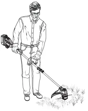
OPERATING THE GRASS TRIMMER
See Figure 11.
Hold the grass trimmer with your right hand on the rear handle and your left hand on the front handle. Keep a firm grip with both hands while in operation. The grass trimmer should be held at a comfortable position with the rear handle at about hip height. Always operate grass trimmer with switch trigger completely depressed. If debris becomes wrapped around the string head, RELEASE THE SWITCH TRIGGER, remove the battery pack, and remove the debris.
![]() WARNING:
WARNING:
Always hold the grass trimmer away from the body keeping clearance between the body and the grass trimmer. Any contact with the cutting head while operating can result in serious personal injury.
![]() WARNING:
WARNING:
Extreme care must be taken when using a blade attachment to ensure safe operation. Read the safety information for safe operation when using a blade attachment and refer to the safety rules and instructions in your attachment manual. The improper operation could result in serious injury.
CUTTING TIPS
See Figure 12.
- Keep the trimmer tilted toward the area being cut; this is the best cutting area.
- The grass trimmer cuts when passing the unit from right to left. This will avoid throwing debris at the operator.
Avoid cutting in the dangerous area shown.
- Use the tip of the line to do the cutting; do not force the string head into uncut grass.
- Wire and picket fences cause extra line wear, even breakage. Stone and brick walls, curbs, and wood may wear line rapidly.
- Avoid trees and shrubs. Tree bark, wood moldings, siding, and fence posts can easily be damaged by the line.
ADVANCING THE CUTTING LINE ON THE BUMP FEED TRIMMER HEAD
Line advance is controlled by tapping the string head on the grass while running the motor at full speed.
- Depress the switch trigger completely.
- Tap the bump knob on the ground to advance the line. The line advances each time the knob is tapped. Do not hold the knob on the ground.
NOTE: The line trimming cut-off blade on the grass deflector will cut the line to the correct length.
NOTE: If the line is worn too short you may not be able to advance the line by tapping it on the ground. If so, remove the battery pack and manually advance the line.
To advance the cutting line manually:
- Remove the battery pack.
- Push the bump knob in while pulling on line(s) to manually advance the line.
ADJUSTING THE LINE CUT-OFF BLADE
See Figures 13 – 14.
This trimmer is equipped with a line cut-off blade on the grass deflector. For best cutting, advance the line until it is trimmed to length by the line cut-off blade. Advance line whenever you hear the motor running faster than normal, or when trimming efficiency diminishes. This will maintain the best performance and keep the line long enough to advance properly. This trimmer is currently set at the 17 in. cutting swath. To adjust to a cutting swath of 15 in.:
- Remove the battery pack.
- Loosen the blade screw then rotate the line cut-off blade 180°.
- Tighten the blade screw.
![]() WARNING:
WARNING:
The line cut-off blade on the grass deflector is sharp. Use gloves while working with the blade. Direct contact with the blade can result in serious personal injury.
MAINTENANCE
![]() WARNING:
WARNING:
To avoid serious personal injury, always remove the battery pack from the tool when cleaning or performing any maintenance.
![]() WARNING:
WARNING:
Always wear eye protection with side shields marked to comply with ANSI Z87.1, along with hearing protection. Failure to do so could result in objects being thrown into your eyes resulting in possible serious injury.
![]() WARNING:
WARNING:
When servicing, use only identical replacement parts. Use of any other parts can create a hazard or cause product damage.
NOTICE:
Periodically inspect the entire product for damaged, missing, or loose parts such as screws, nuts, bolts, caps, etc. Tighten securely all fasteners and caps and do not operate this product until all missing or damaged parts are replaced. Please contact customer service or an authorized service center for assistance.
GENERAL MAINTENANCE
Avoid using solvents when cleaning plastic parts. Most plastics are susceptible to damage from various types of commercial solvents and may be damaged by their use. Use
clean cloths to remove dirt, dust, oil, grease, etc.
![]() WARNING:
WARNING:
Do not at any time let brake fluids, gasoline, petroleum-based products, penetrating oils, etc., come in contact with plastic parts. Chemicals can damage, weaken or destroy plastic which can result in serious personal injury.
LINE AND BLADE REPLACEMENT
See Figures 15 – 18.
Use the original manufacturer’s replacement line for best performance.
- Remove the battery pack.
When using the bump feed trimmer head:
- Rotate the bump knob clockwise as necessary to align the arrows on the bump knob with the arrows on the string head housing.
- Cut one piece of trimmer line 10 ft. long. Insert the line into the eyelet on the string head housing. Push until the end of the line comes out the other side of the housing.
Pull the line until equal amounts of the line appear on both sides of the housing.
NOTE: Line may jam if more than 10 ft. is loaded.
- Either by hand or using the SPEED WINDER™, rotate the bump knob clockwise to wind the line on the spool until approximately 6 in. of the line is showing on each side.
NOTE: For best results, after every five to seven revolutions of the SPEED WINDER™, pull both lines ends taut for best loading results and to help prevent the line from tangling.
- Push the bump knob down while pulling on line(s) to manually advance the line.
When using line in the fixed-line/blade housing: - Remove the old line from the string head by pulling one side of the line.
- Fold an 11 in. piece of pre-cut line in half so each half is equal in length.
- Insert the ends of the line through the eyelet in the post and pull tight.
- Repeat with the other post.
When using blades in the fixed-line/blade housing:
- Remove the fixed-line/blade housing by rotating the lower housing counterclockwise so the posts and the arrows on the upper housing align, then pull the lower housing
away from the upper housing. - Remove the used blades and discard.
- Install the new blades, making sure they are fully seated.
- Reinstall the fixed-line/blade housing as previously described.
CLEARING BUMP FEED TRIMMER HEAD LINE JAM AND/OR REPLACING BUMP KNOB
See Figure 19.
- Remove the battery pack.
- Remove the bump feed trimmer head housing by rotating the lower housing counterclockwise so the arrow on the upper housing aligns with the outside arrow on the bump feed housing.
NOTE: The housing is spring-loaded and will self eject when unlocked. It is not necessary to remove the upper string head housing from the drive shaft. - Push the spool and bump the knob through the string head housing and remove the string from the spool.
- If replacing the bump knob, remove the old knob from the spool. Align the knob ribs with the spool slots and place the new bump knob onto the spool. If you are not
replacing the bump knob, skip this step. - Insert the bump knob and spool assembly through the opening in the string head housing.
- Align the arrows on the lower string head housing with the arrows on the upper string head housing.
- Push the housing together and rotate the lower housing clockwise until the arrows on the lower housing are aligned with the lock on the upper housing.
- Install line as described in Line and Blade Replacement.
CLEANING THE GRASS TRIMMER
- Stop the motor and remove the battery pack.
- Clean dirt and debris from the grass trimmer using a damp cloth with a mild detergent.
NOTICE:
Do not use any strong detergents on the plastic housing or the handle. They can be damaged by certain aromatic oils such as pine and lemon, and by solvents such as kerosene.
TROUBLESHOOTING
| PROBLEM | POSSIBLE CAUSE | SOLUTION |
| Motor fails to start when switch trigger is depressed. | The battery is not secure. The battery is not charged. The battery is hot. | To secure the battery pack, make sure the latch on the bottom of the battery pack is snapped into place. Charge the battery pack according to the instructions included with your model. When the battery pack reaches cooled temperature, the trimmer will resume operation. |
| The line will not advance | The line is welded to itself. Not enough line on the spool. The line is worn too short. The line is tangled on the spool. |
Lubricate with silicone spray. Install more lines. Refer to Line and Blade Replacement earlier in this manual. Pull lines while alternately pressing down on and releasing the bump knob. Refer to Line and Blade Replacement earlier in this manual. Remove the line from the spool and rewind. Refer to Line and Blade Replacement earlier in this manual. |
This product has a Five-year Limited Warranty for personal, family, or household use (90 days for business or commercial use).
For warranty details, visit www.ryobitools.com
or call (toll-free) 1-800-525-2579.
OPERATOR’S MANUAL
• PARTS AND SERVICE: Prior to requesting service or purchasing replacement parts, please obtain your item, manufacturing, and
serial numbers from the product data plate.
ITEM NO.* __________________________________MANUFACTURING NO. _____________________________________________
SERIAL NO. _______________________________________________________
* Model/item number on product may have additional letters at the end. These letters designate manufacturing information and should be provided when calling for service.
HOW TO OBTAIN REPLACEMENT PARTS: Replacement parts can be purchased online at www.ryobitools.com or by calling
1-800-525-2579. Replacement parts can also be obtained at one of our service centers.
HOW TO LOCATE A SERVICE CENTER: Service centers can be located online at www.ryobitools.com or by calling 1-800-525-2579.
HOW TO OBTAIN CUSTOMER OR TECHNICAL SUPPORT: To obtain customer or technical support please contact us at
1-800-525-2579.
RYOBI is a trademark of Ryobi Limited and is used pursuant to a license granted by Ryobi Limited.
TTI OUTDOOR POWER EQUIPMENT, INC.
P.O. Box 1288, Anderson, SC 29622, USA
1-800-525-2579 • www.ryobitools.com
998000742
2-10-22 (REV:06)