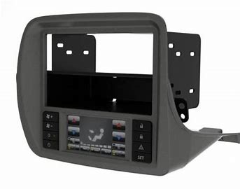
SCOSCHE® GM5201B IN-DASH STEREO INSTALLATION KIT FOR 2010-UP CHEVROLET CAMARO WITH TOUCH-SCREEN INTERFACE
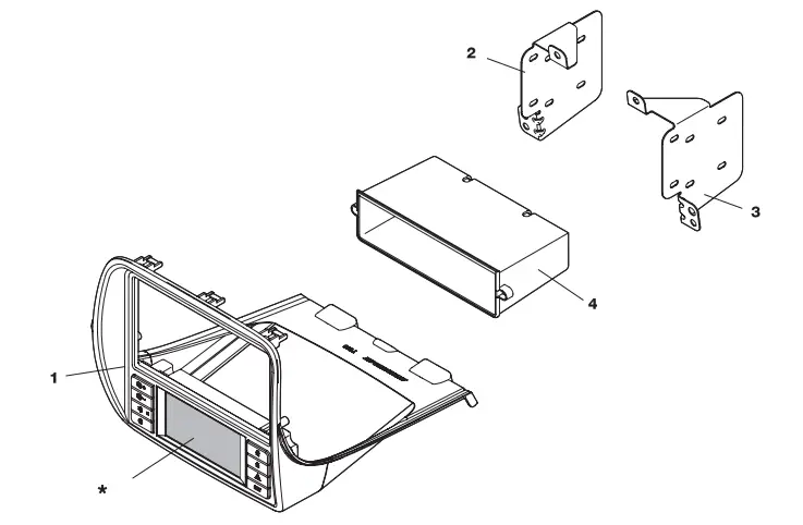
PARTS LIST:
- Main panel with built-in touch screen (*)
- Stereo mounting bracket (left)
- Stereo mounting bracket (right)
- Dash pocket for single din mount
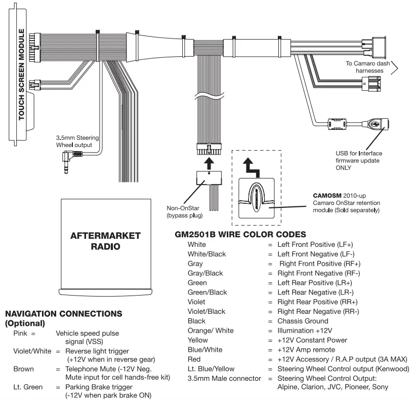
- Power harness (not shown-see page 3)
SOLD SEPARATELY: CAMOSM OnStar retention interface (not shown -see page 3)
INTRODUCTION/PRELIMINARY
This premium installation kit is for 2010-Up Chevrolet Camaro vehicles. Included are all the parts you need to mount your car stereo or CD player into your vehicle’s dash. Refer to the individual instruction in this manual to remove your vehicle’s factory radio and assemble the kit.
CAUTION
DISCONNECT YOUR VEHICLE’S NEGATIVE BATTERY TERMINAL BEFORE THE INSTALLATION TO HELP PREVENT ELECTRICAL DAMAGE. WE RECOMMEND THE USE OF A VOLT/OHM METER OVER A TEST LIGHT TO CHECK WIRING. A TEST LIGHT OR GROUNDED WIRE PROBE CAN CAUSE DAMAGE TO THE VEHICLE’S COMPUTER AND/OR DIAGNOSTIC SYSTEMS. AVOID ALL FACTORY AIRBAG WIRING – AIRBAGS CAN ACCIDENTALLY DEPLOY CAUSING SERIOUS INJURY OR DEATH.
NOTES
- See your vehicle’s instructions for any special tools your installation might require.
- Read all instructions accompanying your car stereo for proper wiring and mounting instructions.
LIABILITY DISCLAIMER
This instruction booklet is based on carefully documented data and research of automobile dash disassembly, wire harness/ codes and information pertaining to installation of this kit (GM5201 B) in 2010-Up Chevrolet Camara vehicles. Scosche Industries, Inc. cannot be held responsible for discrepancies/inconsistencies that may occur due to the automobile manufacturing changes or options, or damage that may occur in the automobile during the installation of components while using this booklet.
If you have any further questions, call our toll free technical help line at: 1-800-621-3695×3
FACTORY STEREO REMOVAL
2010-UP CHEVROLET CAMARO
- Turn ignition to the ON position and shift vehicle into drive.
NOTE: In order to complete step 1 the battery must be connected. After completing step 1, disconnect the negative battery cable and proceed to step 2. - Use a Panel-safe Removal Tool (PR1) to unclip Auxiliary gauge panel, unplug and remove.
- Use a small flathead screw driver, unclip screw cap located on the lower front side of the shift knob.
- Extract (1) T-20 Torx screw to remove gear shift knob.
- Extract (4) 7mm screws securing shifter console, then with pick tool, unclip (1) clip located on each side under the shifter console, unplug and remove.
- Use PRT to unclip each side panel from the center console.
- Extract (1) Phillips head screw from each side located on the outer area of the center console.
- Extract (1) Phillips head screw from each side of center console’s rear panel, lift and pull back to remove.
- Extract (3) Phillips head screws behind center console’s armrest.
- Extract (1) Phillips head screw in front of beverage holder.
- Use PRT to unclip 12V and USB/3.5mm housing inside the armrest, unplug and remove.
- Use PRT to unclip center console and remove.
- Extract (2) 7mm screws securing radio panel located under and to the rear of NC controls. Use PRT to unclip radio fascia panel, unplug, and remove.
- Extract (4) 7mm screws securing radio chassis/ Drive assembly, unplug, lift away and remove
STEREO ASSEMBLY/ MOUNTING
SINGLE DIN ISO INSTALLATION
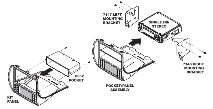
- Attach 6552 pocket to the back the of main kit panel with the (2) supplied screws as shown below.
- Mount the 7147 and 7148 left and right brackets to the sides of the aftermarket stereo using the screws supplied with the stereo.
- Connect and mount the stereo in the dash. The main kit panel/pocket assembly mounts to the dash over the stereo.
DOUBLE DIN ISO INSTALLATION
- Mount the 7147 and 7148 left and right brackets to the sides of the aftermarket stereo using the screws supplied with the stereo.
- Connect and mount the stereo in the dash. The main kit panel mounts to the dash over the stereo.

GM5201 B WIRING DIAGRAM
VEHICLE STARTUP
CONNECTION AND INITIALIZATION PROCEDURE
IMPORTANT NOTE! The connection and startup process below must be followed, or the HVAC touch screen system may not operate properly.
- Re-route factory HVAC connector to radio cavity.
- Connect factory radio connector to Scosche harness.
- Connect factory HVAC connector to Scosche harness.
- IF USING OPTIONAL OnStar® MODULE: Remove looped 20 pin connector from Scosche harness and connect OnStar® module*.
- Move OnStar® module, radio connector, and HVAC connector to the left of the radio cavity.
- Route the 8 and 24 pin connectors of Scosche harness to original location of HVAC connector.
- Connect the Scosche harness along with antenna and all other accessories to the aftermarket radio and insert into radio cavity.
- Enter the car and shut all doors and remove the key.
- Wait approximately 5 minutes for the vehicles computer to enter a sleep state (approx. 2 minutes after dome light turns off).
- You may now connect the 24 pin and 8 pin connectors to the new HVAC controller.
- While still in the vehicle with the doors shut, insert the key and start the vehicle’s engine.
*THE OnStar® MODULE MUST BE CONNECTED BEFORE THE NEW HVAC CONTROLLER CAN BE CONNECTED.*
CLIMATE and CONVENIENCE CONTROLS
The Scosche Touch Screen Interface replaces the factory climate, convenience and personalization controls built into the OEM Factory GM Radio system. This solution provides improved ergonomics while adding touch screen capabilities unique to this system. Read the following sections to familiarize yourself with the operating controls and settings.
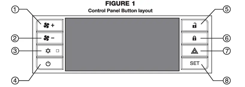
- Fan speed UP
- Fan speed DOWN
- Air conditioning ON/OFF
- Climate power ON/OFF
- Power unlock
- Power lock
- Hazard warning flashers
- SET (Settings)
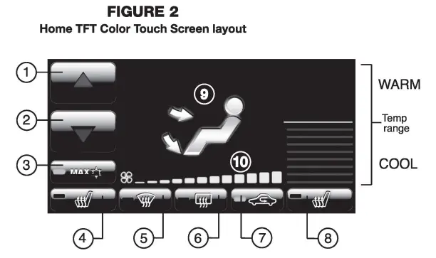
- Air Temp Up
- Air Temp Down
- Max A/C On/Off
- Driver’s Heated Seat
- Defrost
- Rear Defog
- Recirculate
- Pass Heated Seat
- Vent Mode
- Fan Speed Indicator

POWER
Press the Power button (Fig.1, #4) to toggle the climate controls On or Off.
POWER DOOR LOCK CONTROL
 Press the Lock button (Fig.1, #6) to lock both doors.
 Press the Unlock button (Fig.1 , #5) to unlock both doors.
HAZARD WARNING FLASHERS
 Press the Hazard button (Fig.1, #7) to activate flashing signal lamps (flash on and off). This warns ~ others that you are having trouble. Press again to turn the flashers off.
SETTINGS /MENU ACCESS

Press the SET button (Fig.1, #8) to access touch screen, vehicle features and other settings. See “Display Screen” or “Vehicle Feature/Settings” sections for additional information.
FAN SPEED CONTROL

To increase fan speed, press the fan speed UP button on the control panel (pg. 4, Fig. 1, #1). On the color TFT touch screen a graphic level indicator will move up indicating the current fan speed (pg. 4, Fig. 2, #10). There are a total of 12 fan speed increments from completely off to maximum.

To decrease fan speed, press the fan speed DOWN button on the control panel (pg. 4, Fig. 1, #2). – On the color TFT touch screen a graphic level indicator will move down indicating the current fan speed (pg. 4, Fig. 2, #10). Continue pressing the DOWN button to turn fan completely off.
TEMPERATURE CONTROL
Use the UP and DOWN arrows (pg. 4, Fig. 2, #1 & #2) on the color TFT touch screen to adjust vehicle air temperature. Touch the Red arrow to increase air temp. Touch the Blue arrow to decrease air temp. The temperature indicator will move up or down indicating the current temperature level. The temperature range is color-coded: Red indicates warmer air and Blue indicates cooler air.
AIR FLOW/ VENT CONTROL
Touch the vent control mode (pg. 4, Fig. 2, #9) on the color TFT touch screen to toggle through the current vent mode. Graphics are displayed according to the selected vent and airflow pattern.
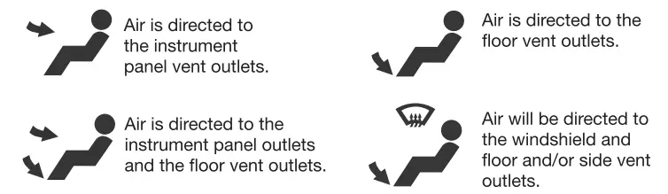
DEFOG / DEFROST CONTROL

Touch the Defog (pg. 4, Fig. 2, #5) on the Color TFT touch screen to turn Defog On or Off. This configuration clears windows of fog or moisture. Air will be directed to the windshield and floor outlets.

Touch the Rear window defogger (pg. 4, Fig. 2, #6] on the Color TFT touch screen to turn the rear window defogger on or off. The rear window defogger turns off automatically 12 minutes. It can also be turned off by turning the ignition to ACC (ACCESSORY) or OFF position. If turned on again it runs for 6 minutes before turning off. At higher vehicle speeds, the rear defogger can stay on continuously.
NOTE: For best results clear the windows of snow or ice before defrost settings. DO NOT OPERATE VEHICLE UNTIL WINDOWS ARE CLEAR!
AIR CONDITIONING
 To turn the air conditioning ON or OFF press A/C button on the control panel (pg. 4, Fig. 1, #3). A Blue indicator light turns on. If the fan is turned off or the outside temperature falls below freezing, the air conditioning will not work. The air conditioning might automatically come on when Defrost mode is selected.
 Touch the MAX A/C button (pg. 4, Fig. 2, #3) on the color TFT touch screen to turn on Max A/C. Maximum cooling will occur with the temperature is adjusted to lowest cold setting and the Fan speed is set at maximum. MAX A/C is used to cool the car down as quickly as possible. Touch the Max A/C button again to return to the previous Fan speed and temp setting.

Touch the Re-circulate button (pg. 4, Fig. 2, #7) on the color TFT touch screen to turn on recirculation. Air will be re-circulated inside the vehicle. This mode helps to quickly cool the air inside the vehicle or prevent outside air and odors from entering. Operating recirculation mode while the A/C is off increases humidity and may cause the windows to fog. Recirculation is not available in the Defrost or Defog modes.
HEATED SEATS
 Touch the driver’s seat heater (pg. 4, Fig. 2, #4) button on the color TFT touch screen to turn on the driver’s seat heater. The engine must be running to use heated seats. A Button graphic will show the level of heat selected: Two lights= high or one light= low). Press the button repeatedly to cycle through the temperature settings or to turn the heated seat OFF.
Touch the passenger’s seat heater (pg. 4, Fig. 2, #8] button on the color TFT touch screen to turn on the Passenger’s seat heater. The engine must be running to use heated seats. A button graphic will show the level of heat selected: Two lights = high or one light = low). Press the button repeatedly to cycle through the temperature settings or to turn the heated seat OFF.
DISPLAY SCREEN SETTINGS
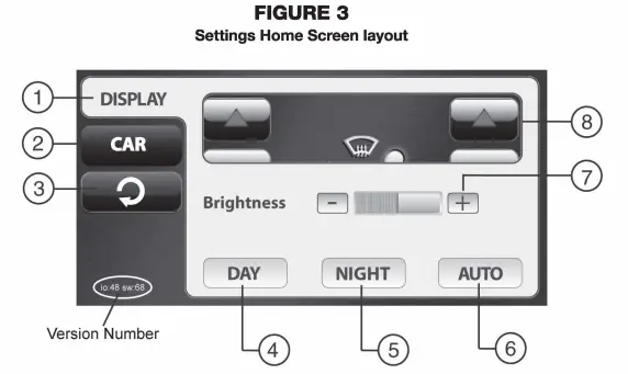
- Display Settings
- Car Settings
- Back/Return
- Day Theme Setting (override)
- Night Theme Setting (override)
- Auto Theme Setting (Vehicle-controlled)
- Brightness Control (TFT screen)
- Preview Window
Other: Software version number appears on lower left corner of set screen.
SETTINGS MENU
Press the “Set” button (Fig. 1, #8) on the control panel to access the user controlled features and settings. The “Settings” Home Screen will appear (Fig. 3) above.
DISPLAY TAB (Default Settings Screen)
Touch the “Display” Tab (Fig. 3, #1) to access various settings for the Touch Screen.
CAR TAB
Touch the “Car” Tab (Fig. 3, #2) to go the second settings menu for access to vehicle comfort and convenience features. See next section “Vehicle Feature Settings”.
RETURN BUTTON
Touch the return button (Fig. 3, #3) to exit settings mode.
DAY THEME
Touch the “DAY” button (Fig. 3, #4) to assign Daytime color theme for the Color TFT touch screen. This setting will keep the display with light colored background regardless of outside environment (overrides Factory control).
NIGHT THEME
Touch the “NIGHT’ button (Fig. 3, #5) to assign Nighttime color theme for the Color TFT touch screen. This setting will keep the display with dark colored background regardless of outside environment (overrides Factory control).
AUTO THEME (Default)
Touch the “AUTO” button (Fig. 3, #6) to assign Automatic (Factory) control of the TFT color theme. This setting will keep Data-controlled switching color theme according to the outside environment. (Light for Daytime / Dark for Nighttime.
BRIGHTNESS
Touch the “+”/”-” Brightness buttons (Fig. 3, #7) to adjust the Brightness of the Color TFT touch screen.
PREVIEW WINDOW
Provides a quick preview of DAY/NIGHT setting changes.
VEHICLE FEATURE / SETTINGS
The color TFT touch screen interface is used to access the vehicle’s built-in customization features.
VEHICLE SETTINGS MENU
Press the “Set” button (see page 4, Fig. 1, #8) on the control panel to access the user controlled features and settings. The “Settings” Home Screen will appear (see page 6, Fig. 3) . Press the CAR button (see page 6, Fig. 3, #2) to access the vehicle features list as shown in Fig. 4 (below).
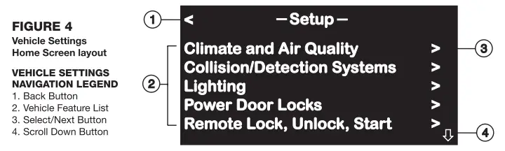
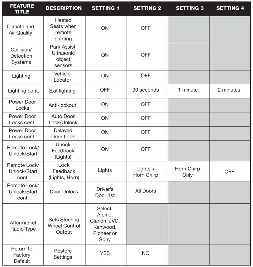
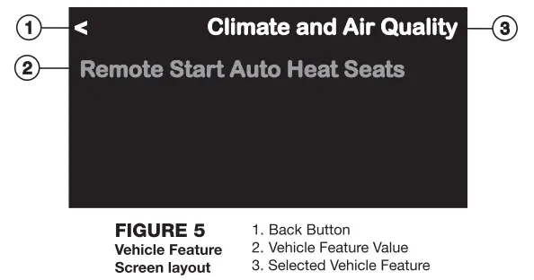
VEHICLE FEATURE DETAILS
- Climate and Air Quality
Heated Seats: On or Off when vehicle is remote started - Collision/Detection Systems
Park Assist feature: Enable or Disable the vehicle’s ultrasonic bumper object sensors (Depends on vehicle options/equipment) - Lighting
Exit Lighting: Set exterior lights delay when exiting vehicle at night
Vehicle Locator Lights: Set exterior lights ON or OFF when unlocking/approaching at night - Power Door Locks
Unlocked Door Anti Lockout: Prevents vehicle locking if Driver door is open (Helps to prevent keys from being locked inside).
Auto Door Unlock: Vehicle unlocks when Shifted into Park (Auto trans) or when Key is removed (Manual Trans)
Delayed Door Lock: Delays door locking - Remote Lock/Unlock/Start
Unlock Feedback (Lights): Enable or Disable vehicle’s Light Flash when Unlocking vehicle with Remote
Locking Feedback: Select the type of audible/visual Lock indicator when Locking vehicle with the Remote – Lights Flash, Lights and Horn blip, or Horn blip only
Door Unlock Options: Selectable unlocking when using remote: Driver’s door first or Both doors at once.
Remote Vehicle Starting: Enable or Disable Remote Vehicle Starting - Aftermarket Radio Type (Steering Wheel Control output)
Select type of Aftermarket Radio for steering wheel interface configuration (Pioneer, Sony, Alpine, Kenwood, Clarion, JVC) - Return to Factory Settings
Restores all customized settings to Factory default: Yes or No
CHANGING FEATURE SETTINGS
HOW TO CHANGE VEHICLE SETTINGS
- Press the “SET” button to access the Configuration/Settings Menu (see page 4, Fig. 1, #8)
- Touch the “CAR” button on the TFT screen (page 6, Fig. 3, #2) to bring up the Car Feature list.
- Touch the name of the Feature you would like to access/change the settings (page 7, Fig. 4 #2). Note: you may need to scroll down to view all options.
- Touch the option value you wish to change and the selected value will turn to GREEN or RED color text.
- Touch the Back button (Fig. 5, #1, above) to go back one level or view other features.
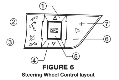
STEERING WHEEL CONTROLS
STEERING WHEEL CONTROL OPERATION (WHEN VEHICLE IS EQUIPPED)
- Seek/Track UP (click SRC button upward)
- Activate OnStar® (if equipped)*
- De-activate OnStar® I Mute Audio
- Seek/Track DOWN (click SRC button downward)
- SRC (Source) – Press in to change source
- Volume DOWN
- Volume UP
*Consult vehicles original owner’s manual for GM OnStar” instructions