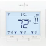
Touch Wi-Fi
Thermostat PRO Installation
Designed by the pros for the pros
There are a lot of choices when it comes to buying a thermostat, but only one combines 125 years of experience and the latest connected home technology to empower your customers o take control of their comfort from anywhere. We proudly connect you to a professional-grade thermostat that you can offer your customers with confidence and that will keep you connected with them even after the initial install.
Sensi partner program
Always be the Contractor-On-Call with your customers. The Sensi app saves your contact information so when your customer needs service, you’re just a tap away. Register at www.sensiregistration.com.
Need help?
Visit sensicomfort.com/support for around-the-clock access to support articles, instructional downloads, and comprehensive support videos. Our highly-trained Sensi Support Team is available seven days a week.
![]() 1.888.605.7131
1.888.605.7131
![]() [email protected]
[email protected]
Easy to install and connect
Sensi is designed to install a standard thermostat. It gives you the flexibility to connect to Wi-Fi at installation or let your customer connect it later using the Sensi app.
MOBILE DEVICE COMPATIBILITY
| OPERATING SYSTEM | COMPATIBILITY |
| iOS | Yes |
| Android | Yes |
| Amazon Fire | Yes |
SMART HOME PLATFORM COMPATIBILITY
| OPERATING SYSTEM | COMPATIBILITY |
| Amazon Alexa | Yes |
| Android | Yes |
| Apple HomeKit | Yes |
HVAC SYSTEM COMPATIBILITY
| SYSTEM TYPE | COMPATIBILITY | MODIFICATIONS |
| ` Conventional heating and cooling • Gas furnace • Air conditioner • Electric furnace • Boiler |
Yes | Requires a common wire (c-wire) |
| Heat only • Gas furnace • Electric furnace • Boiler | Yes | Requires a common wire (c-wire) |
| Cool only • Air conditioner | Yes | Requires a common wire (c-wire) |
| Heat pump | Yes | Requires a common wire (c-wire) |
| Communicating proprietary systems | No | Needs standard HVAC wiring |
| Line voltage | No | Requires low voltage (20-30VAC) |
| Millivolt systems | No | Requires 20-30VAC |
ROUTER COMPATIBILITY
| ROUTER TYPE | COMPATIBILITY |
| Single-band router with 2.4 GHz band | Yes* |
| Dual-band router with 2.4 & 5.0 GHz band | Yes* |
| Single-band router with 5.0 GHz band | Yes |
*Sensi thermostats require an 802.11n 2.4 GHz Wi-Fi network and are compatible with most residential Wi-Fi networks, however, there are some known incompatible routers. Visit support.sensicomfort.com and search “router compatibility” for a list of known incompatible routers.
What’s in the box?
- Sensi Thermostat
- Screws and Anchors
- Wire Labels
Items needed for Wi-Fi connection:
- The homeowner’s compatible iOS or Android
- A device with the Sensi app installed and registered
- Your customer’s Wi-Fi network name (SSID) and password
- A Wi-Fi network with 802.11n 2.4GHz band
QUICK TIP: Ask the homeowner to download the Sensi app and gather their Wi-Fi information while you are installing the thermostat.
Installation
- Turn the terminal light switch on for better visibility.
- Install Sensi thermostat, referring to these terminal definitions, cross-references and wiring diagrams as needed:
| OLD
THERMOSTAT |
SENSI
THERMOSTAT |
CONVENTIONAL
SYSTEM |
HEAT PUMP
SYSTEM |
| RH | RH* | Power for heating, 24V | |
| RC, R | RC* | Power for cooling, 24V | |
| C, X, B** | C | Common wire, 24V | |
| Y, Y1 | Y | 1st stage cool | 1st outdoor stage heat |
| Y2 | Y2/* | 2nd stage cool | 2nd outdoor stage heat and cool |
| W, W1, W/E, Aux/E, E | W/E | 1st indoor
stage heat |
1st stage axillary/ emergency heat |
| W2*** | W2 | 2nd indoor
stage heat |
2nd stage axillary/ emergency heat |
| G | G | Indoor blower (fan) | |
| O,B,** O/B | O/B | Changeover (reversing valve) connection for heat pump or zone panel systems | |
| L | L | no function | “L” terminal connection |
* Two transformer systems (separate RC and RH wires), clip jumper located on the backplate to the right of the terminals.
** Label “B” as “C” only if the old thermostat also had a wire in “O”. If there is no wire on “O”-label the wire “B”.
*** On Heat Pump system with separate W2 and E wires, label both wires W/E (2 wires in one terminal).
SINGLE STAGE OR MULTI (STAGE SYSTEM NO HEAT PUMP) WITH TWO TRANSFORMERS
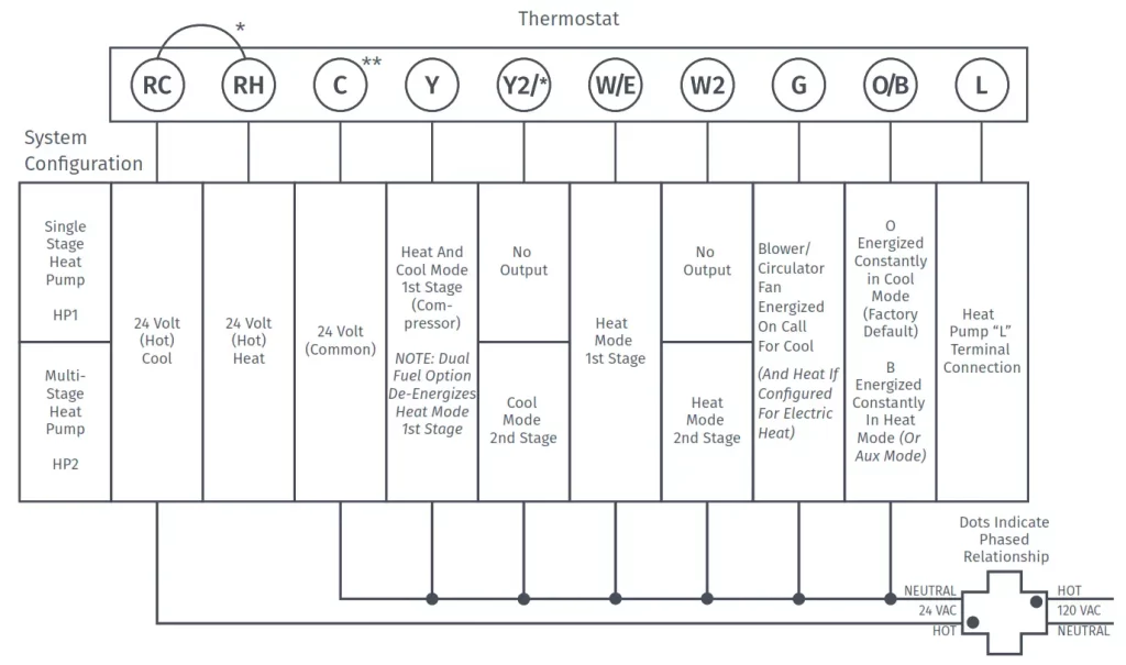
*Two transformers systems (separate RC and RH wires), clip internal RC/RH jumper, located on back of thermostat.
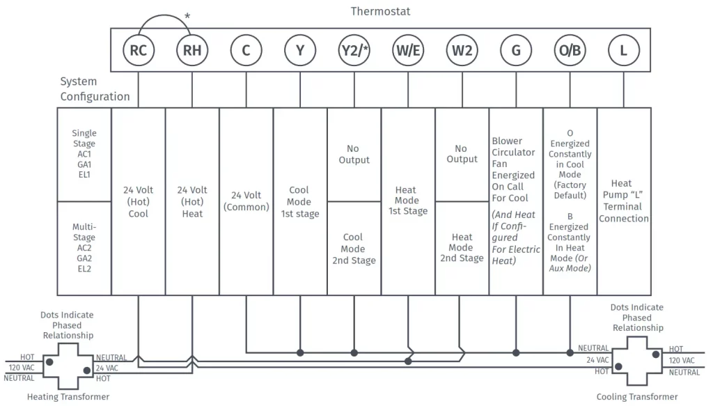
*Internal jumper between RC and RH, located on back of thermostat.
**Common connection required on Heat-only, Cool-only or Heat Pump systems.
Configuration
- Before configuring the thermostat, switch off the terminal light.
- Configure the thermostat to the appropriate system type. Press “Menu” on the thermostat and refer to these menu options as needed:
| OLD THERMOSTAT | Menu item | Default | HEAT PUMP SYSTEM |
| RH | Screen Brightness | Off | Adjust resting-state brightness with an option to turn off |
| RC, R | Backflow | Off | Off / On |
| C, X, B** | Home Screen Content | On On °F |
Indoor Humidity Time of Day °F / °C |
| Y, Y1 | Schedule | – | 5 / 2 Day Schedule |
| Y2 | Wi-Fi | O | Connect to Wi-Fi |
| W, W1, W/E, Aux/E, E | Time Setup | – | Set the date and time |
| W2*** | About Thermostat | – | Model Number/Reset |
| G | Advanced Setup | – | HVAC Equipment | Fan Mode Options |
| O,B,** O/B | HVAC Equipment | AC2 / EL2 AC2 EL2 O |
Outdoor Setup AC1/AC2/HP1/HP2/AC0 Indoor Setup GA1/GA2/EL1/EL2/Fan Reversing Valve Position O/B/3 |
| L | Fan Mode Options Circulating Fan | no function | Off – 100% (5% increments) Off |
3. Once the thermostat is installed and properly configured, test the equipment by following these steps:
- Turn on power to the system.
- Fan Operation
- If your system does not have a “G” terminal connection, skip to “Heating System” below.
- Press the “Fan” button on the thermostat and select the “On” position. The blower should begin to operate.
- Press the “Mode” button to turn off the system. Then press the “Fan” button on the thermostat and select the “Auto” position. The blower should stop immediately.
- Circulating Fan
- Press the “Menu” button on the thermostat and select “Advanced Setup” then select “Fan Mode Options”
- Press “On” to enable circulating fan and set the % run time from 10%-100% in 5% increments (default is OFF).
- The % run time is the percentage of time the fan shall run in a day. This calculation takes into account the amount of time the heating, cooling, and continuous fan have run during the same day.
- Heating System
- Press the “Mode” button on the thermostat and select the “Heat” position.
- Press the up arrow on the thermostat and adjust the setting to 1° above the current room temperature. The heating system should begin to operate and the thermostat display will turn red indicating heating on the screen.
- For heat pumps with auxiliary, press the up arrow on the thermostat and adjust the setting to 3° above the current room temperature. The auxiliary heat should begin to operate and the thermostat will indicate “Heating Auxiliary” on the screen.
- Press the down arrow on the thermostat and adjust the setting to 1° below the current room temperature. The heating system should stop operating and the display will go back to a neutral gray color.
- Cooling System
- Press the “Mode” button on the thermostat and select the “Cool” position.
- Press the down arrow and adjust the setting to 1° below the current room temperature. The blower should come on immediately at high speed, followed by cold air circulation. The thermostat display will turn blue. Note that there can be up to a 5-minute delay for this process.
This is indicated by a flashing setpoint temperature. - Press the up arrow and adjust the setting to 1° above the current room temperature. The cooling system should stop operating and the display will go to a neutral gray color.
- If you encounter any issues while testing the equipment, refer to the troubleshooting actions on page 14.
Troubleshooting
| SYMPTOM | POSSIBLE CAUSE | CORRECTIVE ACTION |
| No Heat/ No Cool/No Fan (common problem) | 1. Blown fuse or tripped circuit breaker 2. Furnace power switch to OFF 3. Furnace blower compartment door panel lose 4. Loose connection to the thermostat tor system |
1. Replace fuse or reset the breaker 2. Turn the switch to ON 3. Replace door panel in the proper position to engage safety interlock or door switch 4. Tighten connections |
| No Heat | 1. Thermostat not set to Heat 2. Loose connection to thermostat or system 3. Heating system requires service or thermostat requires replacement |
1. Set thermostat to Heat. 2. Verify thermostat and system wires are securely attached. 3. Diagnostic: Set Mode to Heat and raise the setpoint above room temperature. Within five minutes the thermostats should make a soft click sound and the display should turn red. This sound indicates the thermostat is operating properly. If the thermostat does not click, try resetting the thermostat. If the thermostat does not click after being reset, contact your heating and cooling service person or place of purchase for a replacement. If the thermostat clicks, verify the heating system is operating correctly. |
| No Cool | 1. Thermostat not set to Cool 2. Loose connection to thermostat or system 3. Cooling system requires service or thermostat requires replacement |
1. Set thermostat to Cool. 2. Verify thermostat and system wires are securely attached. 3. Diagnostic: Set Mode to Cool and lower setpoint below room temperature. The same procedures are as diagnostic for the “No Heat” condition except set the thermostat to Cool and lower the setpoint below the room temperature. There may be up to a five-minute delay before the thermostat clicks in Cooling if the AC Protection feature is on. |
| Heat, Cool or Fan Runs Constantly | Possible short in the wiring, thermostat, heat, cool or fan system |
Check each wire connection to verify they are not shorted or touching other wires. Try resetting the thermostat. |
| Thermostat Display & Thermometer Disagree | Thermostat display requires adjustment |
The display can be adjusted +/-5° using the Temperature Offset in Sensi app. |
| Display is Blank | The display could be turned off of you need a common wire (c- wire) |
Attach a common wire (c-wire)
or turn on the display. |
| Furnace (Air Conditioner) Cycles Too Fast or Slow | The location of the thermostat and/ or the size of the Heating System maybe influencing the cycle rate |
Digital thermostats provide precise control and cycle faster than older mechanical models. The system turns on and off more frequently but runs for a shorter time. If you would like to increase cycle time, choose Slow for the Cycle Rate in the Sensi app. |
| “
Call for Service” appears on the screen |
1. Heating or Cooling system is not able to heat/ cool the space to within 5 degrees of the setpoint within 2 hours 2. If “–” is displayed for the Room Temperature, a replacement thermostat is needed3. None of the buttons operate on the thermostat |
1. See corrective action for “No Heat” See corrective action for “No Cool” 2. Replace thermostat 3. Make sure keypad lockout is not turned on. If it’s OFF, try resetting the thermostat. Reset: Turn the power to your system off, wait 5 seconds, and turn it back on. |
| The fan turns on randomly | The fan has been set to run occasionally in the configuration menu |
Enter the configuration menu and make sure the ‘Fn’ fan run time percentage is OFF. |
Connecting Sensi to Wi-Fi
1. Ask the homeowner to download the free Sensi app onto their iOS or Android device.

2. Ask the homeowner to follow the prompts to create an account.
3. Once the homeowner has logged in, ask to use their device to connect the thermostat to the Wi-Fi.
QUICK TIP: You must have your customer’s Wi-Fi Network (SSID) and Password to complete the wireless setup.
4. Select “Connect Thermostat to WiFi” and follow the in-app prompts to complete the connection steps.
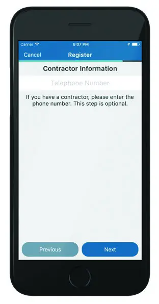
5. Once the thermostat is connected to Wi-Fi, enter your registered phone number by selecting “Settings”, at the bottom then “Contractor Info”.
Warnings
INSTALLER INFORMATION
FAILURE TO READ AND FOLLOW ALL INSTRUCTIONS CAREFULLY BEFORE INSTALLING
OR OPERATING THIS CONTROL COULD CAUSE PERSONAL INJURY AND/OR PROPERTY
DAMAGE.
 WARNING WARNING |
| WARNING: OUT OF PHASE TRANSFORMERS On two transformer systems, the transformers MUST be in phase.Measure the voltage across RC and RH. If more than 12 Volts AC is present between RC and RH, then the transformers are NOT in phase. To correct this condition, reverse the secondary low voltage connections at either the Heating or Cooling transformer. |
| CAUTION |
| To prevent electrical shock and/ or equipment damage, disconnect electric power to the system at the main circuit breaker box until installation is complete. |
| WARNING |
| FOR CALIFORNIA RESIDENTS: WARNING: This product contains a chemical known to the state of California to cause cancer and birth defects and other reproductive harm. |
| WARNING |
| VOLTAGE REQUIREMENTS
Do not use on circuits exceeding specified voltage. Higher voltage will damage control and could cause shock or fire hazards. Thermostat installation and all components of the control system shall conform to Class II circuits per the NEC code. |
| CAUTION |
| CAUTION: E5 Alert
If “Call For Service” is displayed on your Sensi thermostat, and E4 or E5 appears where the room temperature should be displayed or the backlight is flashing, please call our support team immediately at 888.605.7131 |
ATTENTION: MERCURY NOTICE
This product does not contain mercury. However, this product may replace a product that contains mercury. Mercury and products containing mercury must not be discarded in household trash. Refer to hermostatrecycle.org for a location to send products containing mercury.
For Your Customer
MAKE SURE TO LEAVE THE SENSI WELCOME GUIDE FOR YOUR CUSTOMER.
It provides helpful instructions and information on the following:
- How to connect their Sensi thermostat to Wi-Fi (if this has not already been completed) or connect additional devices
- Key features of the thermostat and the app and how they work
- Customer Support
0037-7682002