SIMARINE SC303 and SC503 Digital Shunt
Introduction
Simarine’s high precision SCX03 (SC303 & SC503) active digital shunt measures voltage, current, and temperature of the battery or battery bank.
It can be used for monitoring current draw of heavy consumers (inverters, bow and stern thrusters, anchor winches) and current generators (shore power chargers and solar panels). Additionally, it allows monitoring tanks for fuel, fresh and gray water.
- Innovative combination of shunt and tank level module. SC303 is an active combo shunt for PICO battery monitor with 2 voltages, 2 tank levels or temperature, 1 socket for temperature sensor with JST connector and 1 current sensor up to 300A for up to 75V systems. It can be used for monitoring current draw of heavy consumers (inverters, bow and stern thrusters, anchor winches) and current generators (shore power chargers and solar panels). Additionally, it allows monitoring tanks for fuel, fresh and gray water. SC303 is capable of measuring continuous current up to 300A and suitable for maximal power of 3600W at 12V or 7200W at 24V.
- Innovative combination of shunt and tank level module. SC503 is a high precision combo shunt for PICO battery monitor with 2 voltage, 2 temperature, 1 socket for temperature sensor with JST connector and 1 current sensor up to 500A for up to 75V systems. SC505 is capable of measuring continuous current up to 500A and suitable for maximal power of 6000W at 12V or 12000W at 24V.
Safety
Only qualified electricians with proper safety equipment should make installation of Simarine electronics. When working with batteries, you should wear protective clothing and eye protection.
- CAUTION: Batteries contain acid, a corrosive, colorless liquid that can burn your eyes, skin, and clothing. If the acid comes into contact with eyes or skin, wash out with lukewarm water and immediately seek medical support.
- CAUTION: Do NOT connect anything to a damaged battery. It could heat up, catch fire, or explode.
- CAUTION: Lead-acid batteries can generate explosive gases during operation. Never smoke, allow flames, or sparks near the battery.
- Make sure to keep sufficient ventilation around the battery.
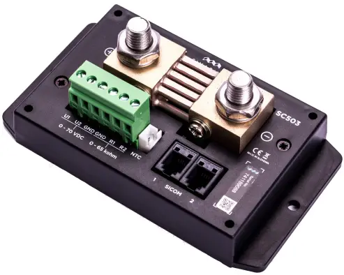
Overview
- A – Battery (+)
- B – Hub – GND (–)
- C – 2 SiCOM ports
- D – 1 JST socket for the temperature sensor
- E – 2 voltage & 2 resistance inputs
Installation
CAUTION: Install the shunt module in a clean and dry place protected from accidental spilling of liquids.
- Remove the shunt cover by unscrewing four screws on top of the shunt cover. To install the shunt use the supplied voltage cables and find a place no further than 3 m away from the battery/battery bank. You can fix the shunt with the supplied screws using two holes on the bottom of the casing.
- Connect all cables.
- Replace the shunt cover and screw the four screws on the cover of the shunt unit.
Cables
For the SiCOM connection use the supplied cable. If not possible, use the following table to determinate the correct cable type.
| CABLES | |
| Cable length | Cable type |
| < 5m | No limitations |
| >= 5m | 2x2x0.25 mm2 twisted pair (recommended) |
- Power cable
Minimum power cable cross-section requirement at maximal temperature of insulation 70°C (160°F).
Continuous current: Area- 500 A: 220mm2
- 400 A: 150mm2
- 300 A: 95mm2
- 200 A: 50mm2
- 100 A: 25mm2
CAUTION: Failure to observe the required cable cross-sections can damage the shunt, wiring, or cause a fire.
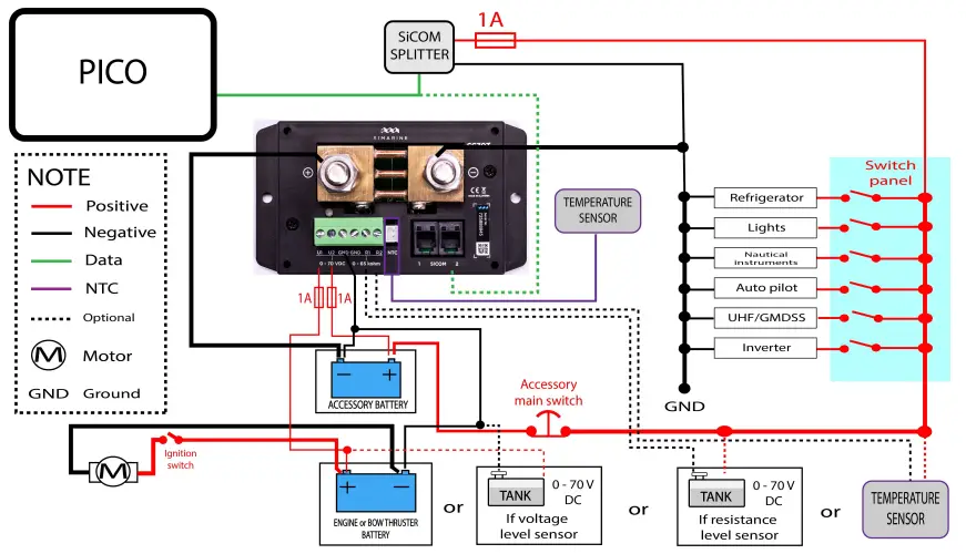
Connecting
For proper function of the Simarine SC3O3/SC5O3 digital shunt it is necessary to take the following steps:
- For safety reasons, disconnect the battery/battery bank plus and minus terminals.
- Connect the shunt to the Simarine PICO via the SiCOM port.
- Connect shunt voltage sensing input to a battery terminal.
- Connect the temperature sensor to the shunt and place it near the battery/battery bank (optional).
- Connect the battery/battery bank minus or plus terminals through the shunt IN terminal.
- Connect all consumers and charging sources to the OUT terminal on the shunt.
Each correctly connected shunt needs to be configured. This can easily be done with the PICO unit. The configuration process is described in the PICO manual.
- The PICO manual & other user manuals: https://simarine.net/manuals
It is recommended that the shunt is installed in the negative line if possible.
CAUTION: After connecting the shunt, make sure all connections between cables and shunt are secured. Loose connections may cause sparks, heating and even a fire. They may also damage the shunt.
SCX03 installed on the minus terminal of the battery
Technical specifications SC303 and SC503
| SC303 | |
| Operating | |
| Voltage range | 6–35V |
| Temperature range | From –20 to +70°C (from –4 to +158°
F) |
| Power consumption at 12V | |
| Operating | 0.8mA |
| Current measuring range | |
| Per channel | 0.01–320A |
| Accuracy | ±0.6% |
| Resolution | 0.01A |
| Sampling rate | 100ms |
| Maximal current | |
| Continuous | 300A |
| Peak current (<1min) | 700A |
| Peak current (<5min) | 400A |
| Voltage drop at 300A | 50mA |
| Maximal voltage on connections | 35V |
| Voltage inputs | |
| Range 0–75V | |
| Accuracy ±0.2% | |
| Resolution 1mV | |
| Sampling rate 100ms | |
| Resistance inputs | |
| Range | 0 Ohm–65kOhm |
| Accuracy | ±3% |
| Temperature sensor – NTC 10k | |
| Range | From –15 to +80°C |
| Accuracy (from –10 to +60°C, from 14 to 140° F) | ±3% |
| Connectivity | Up to |
| Batteries | 1 |
| Temperature sensors | 3 |
| Voltage sensors | 2 |
| SiCOM RJ9 sockets | 2 |
| Installation and dimensions | |
| Dimensions 125 x 70 x 22 mm
4.92 x 2.75 x 0.86 in |
|
| Battery connection M10 bolts | |
| SC503 | |
| Operating | |
| Voltage range | 6–35V |
| Temperature range | From –20 to +70°C (from –4 to +158°
F) |
| Power consumption at 12V | |
| Operating | 1.2mA |
| Current measuring range | |
| Per channel | 0.01–700A |
| Accuracy | ±0.6 % |
| Resolution | 0.01A |
| Sampling rate | 100ms |
| Maximal current | |
| Continuous | 500A |
| Peak current (<1min) | 1000A |
| Peak current (<5min) | 700A |
| Voltage drop at 300A | 50mV |
| Maximal voltage on connections | 35V |
| Voltage inputs | |
| Range | 0–75V |
| Accuracy | ±0.2% |
| Resolution | 1mV |
| Sampling rate | 100ms |
| Resistance inputs | |
| Range | 0 Ohm–65kOhm |
| Accuracy | ±3% |
| Temperature sensor – NTC 10k | |
| Range | From –15 to +80°C |
| Accuracy (from –10 to +60°C, from 14 to 140° F) | ±3% |
| Connectivity | Up to |
| Batteries | 1 |
| Temperature sensors | 3 |
| Voltage sensors | 2 |
| SiCOM RJ9 sockets | 2 |
| Installation and dimensions | |
| Dimensions | 125 x 70 x 22 mm
4.92 x 2.75 x 0.86 |
in |
| Battery connection | M10 bolts | |
Troubleshooting
Negative current values
If PICO is showing the wrong sign for the current value, check if the shunt is correctly installed. This means the battery/battery bank minus (optionally plus) terminal is connected to the IN terminal on the shunt. If this is not the case, you can reinstall the shunt or simply switch the IN and OUT terminal via the shunt configuration on the PICO unit.
Shunt is not visible on PICO
If the shunt is not visible in the PICO menu, check the following:
- Is the shunt properly connected via the SiCOM port to the PICO unit?
- If you are using your own SiCOM cable, make sure it has the right square and is twisted.
- Check if the voltage sensing input is correctly installed and that it does not have plus and minus terminals switched.