Smith GS110W Natural Or Propane Gas Boilers User Manual

BEFORE YOU START
WARNING: This manual must be read and fully understood before installing, operation or servicing this boiler! Failure to follow these instructions could result in a fire or explosion causing extensive property damage, personal injury or death!
These instructions cover the GS110 gas fired, direct vent, low pressure, sectional, cast iron hot water boiler. GS110 boilers have been design certified by CSA for use with natural and propane gas under the latest edition of ANSI-Z21.13/CSA 4.9, Gas-Fired Low Pressure Steam and Hot Water Boilers.
Each unit has been constructed and hydrostatically tested for a maximum working pressure of 30 psi in accordance with the ASME Boiler and Pressure Vessel Code, Section IV for cast iron boilers. Each boiler has been equipped with a 30 psi pressure relief valve.
This manual covers the application, installation, operation and maintenance of a GS110 low pressure hot water boiler.
To obtain the safe, dependable, efficient operation and long life for which this boiler was designed, these instructions must be read, understood and followed.
Direct all questions to your Smith Cast Iron Boiler distributor or to the Customer Service Department, 260 North Elm Street, Westfield, MA 01085. Always include the model and serial numbers from the rating plate of the boiler in question.
The owner should maintain a record of all service work performed with the date and a description of the work done. Include the name of the service organization for future reference.
Where required by the authority having jurisdiction, the installation must conform to the Standard for Controls and Safety Devices for Automatically Fired Boilers, ANSI/ASME CSD-1.
If installed in the Commonwealth of Massachusetts, you MUST FOLLOW the additional instructions contained in Hydrotherm’s instruction sheet MA IOM. If you don’t have a copy, call your Hydrotherm distributor or Hydrotherm.
The installation must conform to the requirements of the authority having jurisdiction or, in the absence of such requirements, to the National Fuel Gas Code, ANSI Z223.1-latest revision. In Canada, the installation must be in accordance with the requirements of CSA B149.1 or B149.2 Installation Code for Gas Burning Appliances and Equipment.
BOILER RATINGS and CAPACITIES
Before undertaking the installation of the GS110 check the boiler rating plate to ensure that the boiler is the proper size for the job. The “Net I=B=R Ratings” specify the equivalent amount of direct cast iron radiation that the boiler can handle under normal conditions.
Also ensure that the boiler has been set up for the type of gas available at the installation site. Other important considerations are the availability of an adequate electrical supply, fresh air for combustion and proximity a suitable outside wall.
BOILER LOCATION
WARNING: The clearances to combustible construction show in Figure 1 must be maintained. Failure to comply with this warning can result in extensive property damage, severe personal injury or death!
CAUTION: Do not lift the boiler by the jacket. Use a hand truck under the base frame as shown in Figure 2.
- Locate the boiler in an area that provides good access to the unit. Keep in mind that servicing may require the removal of jacket panels. Accessibility clearances must take precedence over fire protection clearances.
Figure 1 – Clearances to Combustible Construction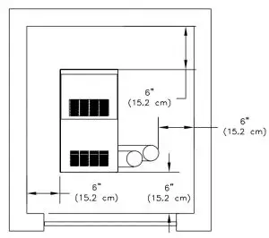
- An optimum site will be level, central to the hot water piping system, close to an outside wall and have adequate fresh air for combustion.
- Ensure that the floor is structurally sound and will support the weight of the boiler.
NOTE: This boiler is designed for direct placement on a combustible floor. Never install this boiler on carpeting! - DO NOT install this boiler in a location that would subject any of the gas ignition components to direct contact with water or excessive moisture during operation or servicing.
- NEVER store objects on or around the boiler
WARNING: Never store combustible materials, gasoline or any product containing flammable vapors or liquids in the vicinity of the boiler. Failure to comply with this warning can result in extensive property damage, severe personal injury or death!
Figure 2 – Moving Boiler


COMBUSTION AIR and VENTILATION
WARNING: This boiler must be supplied with combustion air in accordance with Section 5.3, Air for Combustion & Ventilation, of the latest revision of the National Fuel Gas Code, ANSI Z223.1/NFPA 54 and all applicable local building codes. Canadian installations must comply with CSA B149.1 or .2 Installation Code for Gas Burning Appliances and Equipment, or applicable provisions of the local building codes. Failure to provide adequate combustion air for this boiler/water heater can result in excessive levels of carbon monoxide which can result in severe personal injury or death!
To operate properly and safely this boiler requires a continuous supply of air for combustion. NEVER store objects on or around the boiler!
CAUTION: Combustion air contaminated with fluorocarbons or other halogenated compounds such as cleaning solvents and refrigerants will result in the formation of acids in the combustion chamber. These acids will cause premature failure of the boiler voiding the warranty!
CAUTION: If the boiler is operated while the building is under construction it MUST be protected from wood, concrete, sheet rock and other types of dust. Failure to properly protect the unit from construction dust will damage the unit voiding the warranty!
Buildings may require the installation of a fresh air duct or other means of providing make-up air if the intake air option isn’t used. Any building utilizing other gas burning appliances, a fireplace, wood stove or any type of exhaust fan must be checked for adequate combustion air when all of these devices are in operation at one time. Sizing of an outside air duct must be done to meet the
requirements of all such devices.
WARNING: Never operate this boiler in an environment subjected to a negative pressure unless the air intake is connected to the outdoors. Failure to comply with this warning can result in excessive levels of carbon monoxide causing severe personal injury or death!
All Combustion Air From Inside The Building
Older houses often have enough “leakage” to provide an adequate amount of combustion air provided that the demand for combustion air is not too great, Figure 3. Homes that are relatively new or “tight” will most likely require that the combustion be ducted to the boiler from outside the building. Any home utilizing other gas burning appliances, a fireplace, wood stove or any type of exhaust fan must be checked for adequate combustion air when all of these devices are in operation at one time.
If the boiler is to be located in an alcove, closet or other confined space the distances from the boiler and it’s vent system to all-combustible construction must be equal to or greater than the minimum clearances in Figure 1. When installed in a closet or confined space two permanent openings of equal area adjoining another room or rooms having sufficient volume to meet the requirements of an unconfined space must be provided, Figures 4 & 5. Each opening must have a minimum free area of one square inch per 1000 Btu/hr (2200 mm2 / kW) based on the total input rating of all gas utilization equipment in the confined area. Each opening must be no less than 100 square inches (64516 mm2 ) in size. The upper opening must be within 12 inches (305 mm) of, but not less than 3 inches (76 mm) from, the top of the enclosure. The bottom opening must be within 12 inches (305 mm) of, but not less than 3 inches (76 mm) from, the bottom of the enclosure
All Combustion Air From Outside The Building
When installed in a confined space without the intake air option two permanent openings communicating directly with, or by ducts to, the outdoors or spaces that freely communicate with the outdoors must be present. The upper opening must be within 12 inches (305 mm) of, but not less than 3 inches (76 mm) from, the top of the enclosure. The bottom opening must be within 12 inches (305 mm) of, but not less than 3 inches (76 mm) from, the bottom of the enclosure.
Where directly communicating with the outdoors or communicating with the outdoors through vertical ducts, each opening shall have a minimum free area of 1 in2 / 4000 Btu/hr (550 mm2/kW) of the total input rating of all of the equipment in the enclosure.
Where communicating with the outdoors through horizontal ducts, each opening shall have a minimum free area of 1 in2 /2000 Btu/hr (1100 mm2 /kW) of the total input rating of all of the equipment in the enclosure.
When ducts are used, they must have the same crosssectional area as the free area of the opening to which they connect. Sizing of an outside air duct must be based on the total input rating of all gas utilization equipment in the confined space.
When calculating the free area necessary to meet the make-up air requirements of the enclosure, consideration must be given to the blockage effects of louvers, grills and screens.
Screens must have a minimum mesh size of 1/4″ (6.4mm). If the free area through a louver or grill is not known ducts should be sized per Table 1.
Table 1 – Combustion Air Duct Sizing
FreshAir Duct Size: Input Btuh 1/4” Wire Screen Mesh: Input Btuh Metal Louvers: Input Btuh Wooden Louvers
3” x 12”: 144,000: 108,000: 36,000
8” x 8”: 256,000: 192,000: 64,000
8” x 12”: 384,000: 288,000: 96,000
8-1/2” x 16: 512,000: 384,000: 128,000
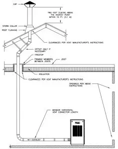
Figure 3 – Horizontal Positive Pressure Venting Using Inside Combustion Air (Cat. III) Figure 4 – Vertical Negative Pressure Masonry Chimney System Using Inside Combustion Air (Cat. I)
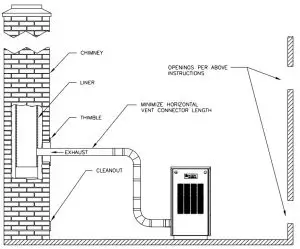
Figure 5 – Vertical Negative Pressure Metal Chimney System and Inside Combustion Air (Cat. I)
Intake Air Option – General Guidelines
This configuration provides combustion air directly to the boiler using a dedicated pipe. Combustion air can be drawn in horizontally through an outside wall or vertically through the roof, see Figures 6, 7, 8, 9 & 10.
WARNING: Each boiler must have it’s own intake air system. Common intake air systems are not to be used! Improper installation can result in excessive levels of carbon monoxide which can cause severe personal injury or death!
Single wall galvanized smoke pipe, single wall aluminum pipe, flexible aluminum pipe, PVC or CPVC pipe can be used for the intake air pipe. Maximum intake lengths must not be exceeded per Table 2, larger diameters may be used on 3,4,and 5 section boilers.
Table 2 – Combustion Air System Sizing
Boiler Model Number: Equivalent Intake Length (see note) 3” Diameter: Equivalent Intake Length (see note) 4” Diameter:
GS110-3, 45 feet (13.7 m), 65 feet (19.8 m)
GS110-4, 45 feet (13.7 m), 65 feet (19.8 m
GS110-5, 45 feet (13.7 m), 65 feet (19.8 m)
GS110-6, n/a, * 40 feet (12.2 m)
GS110-7, n/a, * 40 feet (12.2 m)
* 4″ to 3″ reducer required.
Note: Subtract 5 feet (1.5 m) for each 90° elbow.
All joints in metal intake air systems must be secured using corrosion resistant fasteners and sealed using a suitable Silicone caulk. If PVC or CPVC is used, the joints must be cleaned with a suitable solvent and connected using a solvent based PVC cement. The intake air system MUST be supported by the building structure not the boiler/water heater.
Intake Air Option – Vertical Guidelines
A listed, nonrestrictive intake air cap must be used. The intake air cap must terminate as shown in Figure 6. The penetration point in the roof must be properly flashed and sealed.
Figure 6 – Vertical Positive Pressure Venting with Outdoor Combustion Air (Cat. III)
Intake Air Optional – Horizontal Guidelines
The maximum equivalent length for the horizontal intake air pipe is listed in Table 2. The intake air system must be pitched down, toward the terminal, 1/4″ per foot (21 mm per meter).
If horizontal runs exceed 5 feet (1.5 m) they must be supported at 3 foot (0.98 m) intervals with overhead hangers. Figures 7 through 10 show the four horizontal air intake options. The intake terminations certified for use the GS110 are listed in Table 5.
Figure 7 – Horizontal Positive Pressure Venting with Outdoor Combustion Air
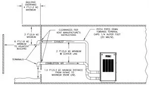
Figure 8 – Horizontal Positive Pressure Venting with Outdoor Combustion Air
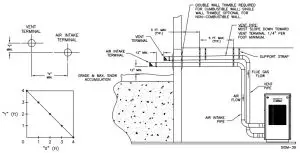
Figure 9 – Vertical Negative Pressure Masonry Chimney System using Outside Combustion Air (Cat. I)
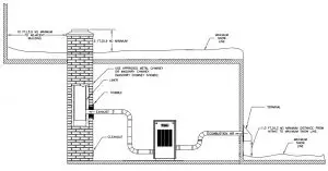
Figure 10 – Vertical Positive Pressure Venting using Outside Combustion Air (Cat. III)

GENERAL VENTING GUIDELINES
WARNING: The vent installation must be in accordance with Part 7, Venting of Equipment, of the National Fuel Gas Code, ANSI Z223.1/ NFPA 54-latest revision or applicable provisions of the local building codes. Canadian installations must comply with CSA B149.1 or.2 Installation Code. Improper venting can result in excessive levels of carbon monoxide whichcan result in severe personal injury or death!
WARNING: Thimbles and fire-stops must be used where required. A minimum clearance of 6″ must be maintained between single wall metal vents and combustible construction or a fire resulting in severe personal injury or death may occur!
WARNING : Each boiler/water heater must have it’s own vent system. Common positive pressure vent systems are not to be used! Improper installation can result in excessive levels of carbon monoxide which can cause severe personal injury or death!
All vent systems must be fully supported by the building structure and not by the boiler/water heater.
VENT SYSTEM OPTIONS
The GS110 may be vented the following ways:
- Direct Vent (Positive Pressure), uses a vent system certified to UL 1738 for installations in the United States, ULS636 for installations in Canada. Combustion air is piped from the outdoors to the blower inlet.
- Horizontal Vent (Positive Pressure), uses a vent system certified to UL 1738 for installations in the United States, ULS636 for installations in Canada. Combustion air is obtained from the space in which the unit is installed.
- Vertical Vent (Positive Pressure), uses a vent system certified to UL 1738 for installations in the United States, ULS636 for installations in Canada. Combustion air is piped from the outdoors to the blower inlet or is obtained from the space in which the unit is installed.
- Vertical/Chimney Vent (Negative Pressure), uses an approved metal chimney system or masonry chimney. Combustion air is obtained from the space in which the unit is installed or is piped from the outdoors to the blower inlet.
Certified vent systems are manufactured by the following companies:
Heat-fab, Inc.
130 Industrial Blvd., Turners Falls, MA 01376
(800) 772-0739.
Z-Flex U.S., Inc.
20 Commerce Park North, Bedford, NH 03110-6911
(800) 654-5600.
Protech Systems Inc.
26 Gansevoort Street, Albany, NY 12202
(518) 463-7284
GENERAL DIRECT VENT INFO
In this configuration the boiler blower is used to push the flue products to the outdoors while drawing combustion air from the outdoors. The instructions under the COMBUSTION AIR & VENTILATION SECTION must be followed! The vent system must be sized per Table 3.
Table 3 – Positive Pressure Vent System Sizing
Boiler Model Number: Equivalent Intake Length (see note) 3” Diameter: Equivalent Intake Length (see note) 4” Diameter:
GS110-3, 45 feet (13.7 m), 65 feet (19.8 m)
GS110-4, 45 feet (13.7 m), 65 feet (19.8 m
GS110-5, 45 feet (13.7 m), 65 feet (19.8 m)
GS110-6, n/a, * 40 feet (12.2 m)
GS110-7, n/a, * 40 feet (12.2 m)
* 4″ to 3″ reducer required
Note: Subtract 5 feet (1.5 m) for each 90° elbow.
HORIZONTAL DIRECT VENT SYSTEMS
See figures 7 & 8. The vent materials used in horizontal positive pressure vent systems must be certified to UL 1738 for installations in the United States, ULS636 for installations in Canada
Each 90° elbow is equal to 5 linear feet (1.5 m) of pipe.To maximize the performance of single wall sheet metal vent systems locate 90° elbows as far from the boiler as possible and from one another. For best results, horizontal vent systems should be as short and straight as possible. The vent system must be both gas tight and watertight. All seams and joints in metal pipes must be joined and sealed in accordance with the vent system manufacturer’s instructions.
When horizontal vent runs exceed 5 feet (1.5m) they must be supported at 3 foot (0.98 m) intervals with overhead hangers. The vent system must be pitched down, toward the vent terminal, 1/4″ per foot (21mm per meter). If any part of a single wall metal vent system passes through an unheated space it must be insulated with insulation rated for 400°F. Structural penetrations must be made using approved thimbles.
Horizontal vent systems shall terminate at least 4 feet(1.3 m) below, 4 feet (1.3 m) horizontally from or 1 foot (0.23 m) above any door, window or gravity air inlet into any building. It must not terminate less than 4 feet (1.3 m) horizontally from, and in no case above or below, unless a 4 feet (1.3 m) horizontal distance is maintained, from electric meters, gas meters, regulators and relief equipment and not less than 7 feet (2.3 m) from any adjacent public walkway. The bottom of the vent terminal(s) shall be located at least 5 feet (1.5 m) above the air intake terminal(s). Avoid terminal locations likely to be affected by winds, snowdrifts, people and pets.
Table 4 – Certified Vent and Intake Terminals
Company: Part No.: Description: Dia (in.):
Protech, 300311, Tee, 3
Protech, 300312, Tee, 4
Protech, 300186, Bird Screen, 3
Protech, 300187, Bird Screen, 4
Protech, 300130, 45° Elbow, 3
Protech, 300131, 45° Elbow, 4
Protech, 300160, 90° Elbow, 3
Protech, 300161, 90° Elbow, 4
Heat-Fab, 7390GC, Mitered, 3
Heat-Fab, 7490GC, Mitered, 4
Heat-Fab, 7390TEE, Tee, 3
Heat-Fab, 7490TEE, Tee, 4
Heat-Fab, 7392GC, Screen,
Heat-Fab, 7492GC, Screen,
Heat-Fab, 7314TERM, 90° Elbow, 3
Heat-Fab, 7414TERM, 90° Elbow, 4
VERTICAL DIRECT VENT SYSTEMS
See Figures 6 & 10. The vent materials used in vertical positive pressure vent systems must be certified to UL 1738 for installations in the United States, ULS636 for installations in Canada.
The maximum length for the vertical vent system is listed in Table 4.
Each 90° elbow is equal to 5 linear feet (1.5 m) of pipe. To maximize the performance of single wall sheet metal vent systems locate 90° elbows as far from the boiler as possible and from one another. If any part of a single wall metal vent system passes through an unheated space it must be insulated with insulation rated for 400°F. Structural penetrations must be made using approved fire-stops.
The vent system must be both gas tight and watertight. All seams and joints in metal pipes must be joined and sealed in accordance with the vent system manufacturer’s instructions.
Vertical vent systems must be terminated with an approved terminal cap as shown in Figures 6 & 10.
HORIZONTAL VENT POSITIVE PRESSURE SYSTEMS
See Figure 3. The vent materials used in horizontal positive pressure vent systems must be certified to UL 1738 for installations in the United States, ULS636 for installations in Canada.
The maximum vent lengths are listed in Table 3.
Each 90° elbow is equal to 5 linear feet (1.5 m) of pipe. To maximize the performance of single wall sheet metal vent systems locate 90° elbows as far from the boiler as possible and from one another. Horizontal vent systems should be as short and straight as possible.
When horizontal vent runs exceed 5 feet (1.5 m) they must be supported at 3 foot (0.98 m) intervals with overhead hangers. The vent system must be pitched down, toward the vent terminal, 1/4″ per foot (21 mm per meter). If any part of a single wall metal vent system passes through an unheated space it must be insulated with insulation rated for 400°F. Structural penetrations must be made using approved thimbles.
The vent system must be both gas tight and watertight. All seams and joints in metal pipes must be joined and sealed in accordance with the vent system manufacturer’s instructions.
Horizontal vent systems shall terminate at least 4 feet (1.3 m) below, 4 feet (1.3 m) horizontally from or 1 foot (0.23 m) above any door, window or gravity air inlet into any building. It must not terminate less than 4 feet (1.3 m) horizontally from, and in no case above or below, unless a 4 feet (1.3 m) horizontal distance is maintained, from electric meters, gas meters, regulators and relief equipment and not less than 7 feet (2.3 m) from any adjacent public walkway. The bottom of the vent terminal(s) shall be located at least 5 feet (1.5 m) above the air intake terminal(s). Avoid terminal locations likely to be affected by winds, snowdrifts, people and pets. Protect building materials and vegetation from degradation caused by flue gasses.
Table 5- Certified Vent Terminals
Company: Part No.: Description: Dia (in.):
Protech, 300311, Tee, 3
Protech, 300312, Tee, 4
Protech, 300130, 45° Elbow, 3
Protech, 300131, 45° Elbow, 4
Protech, 300160, 90° Elbow, 3
Protech, 300161, 90° Elbow, 4
Heat-Fab, 7390TEE, Tee, 3
Heat-Fab, 7490TEE, Tee, 4
Heat-Fab, 7314TERM, 90° Elbow, 3
Heat-Fab, 7414TERM, 90° Elbow, 4
VERTICAL VENT POSITIVE PRESSURE SYSTEMS
See Figure 11. The vent materials used in vertical positive pressure vent systems must be certified to UL 1738 for installations in the United States, ULS636 for installations in Canada.
The maximum vent lengths are listed in Table 3.
Each 90° elbow is equal to 5 linear feet (1.5 m) of pipe. To maximize the performance of single wall sheet metal vent systems locate 90° elbows as far from the boiler as possible and from one another. If any part of a single wall metal vent system passes through an unheated space it must be insulated with insulation rated for 400°F. Structural penetrations must be made using approved fire-stops.
The vent system must be both gas-tight and watertight. All seams and joints in metal pipes must be joined and sealed in accordance with the vent system manufacturer’s instructions. Vertical vent systems must terminate as shown in Figures 6 & 11. An approved terminal cap must be used.
VERTICAL VENT NEGATIVE PRESSURE SYSTEMS
See Figures 4, 5 & 9. The GS110 is listed as a Category I appliance when vented vertically into a metal chimney system or masonry chimney sized as listed in Table 6.
WARNING: If an appliance using any type of a mechanical draft system operating under positive pressure is connected to a chimney flue, never connect any other appliances to this flue. Doing so can result in excessive levels of carbon monoxide which can cause severe personal injury or death!
Chimney Inspection and Sizing
A thorough inspection of the masonry chimney must be performed to ensure that the chimney is clean, properly constructed and properly sized. Exterior masonry chimneys should not be used unless properly lined to prevent condensation and draft problems. Table 6 lists the equivalent breeching and flue sizes required for the boiler/water heater. When more than one appliance is connected to the same chimney flue the flue must be large enough to safely vent the combined output of all of the appliances
Table 6 – Equivalent Breeching and Chimney Size
Boiler Model: Vent & Chimney Diamete inches (mm): Intake Diameter inches (mm)
GS110-3 3 (7.6), 3 (7.6)
GS110-4, 4 (10.2), 3 (7.6)
GS110-5, 4 (10.2), 3 (7.6)
GS110-6, 5 (12.7), 4 (10.2)
GS110-7, 5 (12.7), 4 (10.2)
Note: These sizes are based on a 20 foot (6.1m)
chimney height.
The vent connector should be sloped up toward the chimney 1/4″ per foot. Ensure that the vent connector is properly supported and each connection securely fastened with at least 3 corrosion resistant sheet metal screws. The termination of the vent pipe must be flush with the inside of the chimney flue.
CAUTION: The vent connector length must never exceed 3/4 of the height of the chimney or venting problems will occur!
Figure 11 – Vertical Positive Pressure Venting (Cat. III)
CONDENSATE PIPING
A small amount of condensate is generated on start up. To prevent an excess amount of condensate collecting in the flue collector a condensate drain has been provided. A condensate trap or pump MUST be connected to the condensate fitting in the bottom of the flue collector
A trap can be made by tie wrapping a 4” loop in a piece of vinyl hose attached to the condensate drain fitting. The trap must be filled with water to prevent flue gassses from escaping, see Figures 12 A and B.
A condensate hose has been supplied with boiler and is located inside the literature bag. Installing contractor will have to continue the run of condensate to a nearby drain or pump.
Figure 12A- Condensate Trap
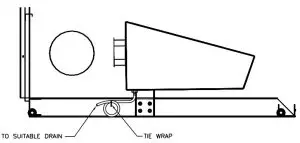
Figure 12B- Condensate Trap

WARNING: Failure to connect a condensate trap or pump to the flue collector can result in excessive levels of carbon monoxide which can cause severe personal injury or death!
HEATING SYSTEM PIPING
CAUTION: All heating system piping must be installed in accordance with the ANSI/ASME Boiler and Pressure Vessel Code, Section IV. All applicable local codes and ordinances must also be followed. If the boiler is installed above any radiation elements it must be fitted with a low water cutoff device installed above the normal boiler water level!
The GS110 hot water boiler comes from the factory ready to be piped to the heating system. Each boiler is equipped with a safety relief valve which must be piped in accordance with the ANSI/ASME Boiler and Pressure Vessel Code, Section IV, see Figure 13.
Table 7 – Boiler Water Volume
Water Volume
Boiler Model: Gallons: Liters:
GS110-3, 1.8, 6.8
GS110-4, 2.4, 9.1
GS110-5, 3.0, 11.4
GS110-6, 3.6, 13.6
GS110-7, 4.2, 15.9
Figure 13 – Relief Valve Piping
Ensure that the boiler is level from front to back and from side to side. Use metal shims to level the boiler. NEVER use combustible materials for shims.
Bypass Piping
CAUTION: Never connect this boiler directly to a large volume system, in-floor radiant system, snow melt system or any other system that would cause the steady state water temperature in the boiler to drop below 140°F. To prevent damage due to excessive condensation, one of the following piping options must be used or the boiler warranty will be voided!
CAUTION: The blend pump arrangement shown in Figure 16 must be used when the flow from any zone in a multiple zone system is less than 4 GPM or boiler short cycling on the high limit will occur!
For the three systems listed below, adjust the bypass valve to divert some of the heated water back into the boiler’s return piping. When adjusted correctly the temperature of the boiler water will exceed 140°F within five minutes of a warm start. A plug valve should be used as the bypass valve for best system performance.
NOTE: Some of the circulator’s capacity will be used in the blending process for the first two systems. Large heating systems may require a larger circulator.
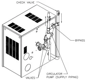
System Bypass
The system bypass shown in Figure 14 should be used on single zone systems, or multiple zone systems using zone valves, when the circulator is installed in the return piping. The bypass must be installed between the supply and return pipes on the suction side of the circulator.
Figure 14 – System Bypass Piping
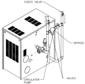
Pump Away Bypass
The system bypass shown in Figure 15 should be used on single zone systems, or multiple zone systems using zone valves, when the circulator is installed in the supply piping. The bypass must be installed between the supply and return pipes on the pressure side of the circulator.
Figure 15 – Pump Away Bypass Piping
Pumped Blend Bypass
The system bypass shown in Figure 16 should be used on multiple zone systems. The bypass must be installed between the supply and return pipes on the suction side of the zone circulators. The bypass valve must be installed on the pressure side of the bypass circulator.
Figure 16 – Pumped Bypass Piping
Piping For Use With Cooling Units
The boiler, when used in connection with a refrigera-tion system must be installed so the chilled medium is piped in parallel with the boiler. Appropriate valves must be used to prevent the chilled water from entering the boiler.
When a boiler is connected to a heating coil that may be exposed to refrigerated air from an air handling device, the piping system must be equipped with flow-control valves or some other automatic means of preventing gravity circulation of the boiler water during the cooling cycle.
Circulators
The TACO 007 circulator supplied with the boiler is sized for use in a closed heating system with a 30 psi maximum operating pressure. If the 007 circulator does not have the required capacity for the system in which it is to be installed, an extra zone circulator or a higher capacity circulator will be needed. Figure 17 depicts the performance curve for the TACO 007 circulator.
Figure 17 – TACO 007 Performance Curve
GAS SUPPLY PIPING
The GS110 hot water boiler comes from the factory ready to be piped to the gas supply. The gas supply can be piped from the left or right side of the boiler.
GS110 Section Size: Connection Tapping:
3, 1/2″
4, 1/2″
5, 1/2
6, 3/4″
7, 3/4″
If for any reason the boiler is not for the type of gas available at the installation site, call the nearest Smith Cast Iron Boiler distributor to resolve the problem.
Figure 18 depicts the proper way to connect the boiler to the gas supply piping. The manual shut-off valve MUST be installed in the supply piping. It should be approximately 5 feet above the floor. Provide a sediment trap/drip leg at the bottom of the vertical section of the gas supply pipe. A ground joint union should be installed between the boiler gas controls and the supply piping. Each of these items is needed to ensure long life and ease of servicing. Always use a pipe sealant that is suitable for use with LP gas.
Figure 18 – Gas Supply Piping
CAUTION: Always use a wrench on the gas valve body when making gas connections to it. Never over-tighten the piping entering the gas valve body or the gas valve will be damaged!
Table 8 should be used to ensure that the gas supply piping is sized properly. If more than one appliance is supplied by the same supply pipe, the piping must be sized based on the maximum possible demand. Do not neglect the pressure drop due to pipe fittings. Table 9 should be used in conjunction with Table 8 to ensure that the gas supply piping is sized properly.
Safe lighting and other performance criteria were met with the gas manifold and control assembly provided on the boiler when the boiler underwent tests specified in ANSI Z21.13. All gas connections MUST be leak tested before putting the boiler into operation.
Table 8 – Gas Pipe Capacity
Note: Maximum pipe capacity in ft3 /hr is based on a 0.60 specific gravity gas at a pressure of 0.5 psig and a 0.3″ WC pressure drop.
Table 9 – Equivalent Pipe Length Chart
Whenever the gas supply piping is pressure tested the boiler gas controls must be protected. If the test pressure is equal to, or less than 1/2 psig (3.5 kPa) isolate the boiler by closing it’s manual shut off valve, see Figure 18. If the test pressure is greater than 1/2 psig (3.5 kPa), disconnect the boiler and it’s individual shutoff valve from the gas supply piping.
WARNING: Never use an open flame to test for gas leaks. Always use an approved leak detection method. Failure to comply with this WARNING could result in an explosion!
ELECTRICAL WIRING
CAUTION: Label all wires prior to disconnection when servicing controls. Wiring errors can cause improper and dangerous operation!
The electrical connections to this boiler/water heater must be made in accordance with all applicable local codes and the latest revision of the National Electrical Code, ANSI /NFPA-70. Installation should also conform with CSA C22.1 Canadian Electrical Code Part I if installed in Canada. Install a separate 120 volt 15 amp circuit for the boiler. A properly rated shut-off switch should be located at the boiler. The boiler must be grounded in accordance with the authority having jurisdiction, or if none, the latest revision of the National Electrical Code, ANSI/NFPA-70.
Line voltage field wiring of any controls or other devices must use copper conductors with a minimum size of #14 awg. Low voltage wiring must not be less than #18 awg with a neoprene, thermoplastic or other equivalent insulation having a minimum insulation thickness of 0.012 inches.
Refer to Figures 19A and 19B for proper wiring connections.
Thermostat Installation
ALWAYS follow the instructions included with the thermostat to be used to control the boiler. Proper location of the thermostat will ensure efficient trouble-free operation of the boiler. Mount the thermostat to an inside wall at a height approximately five feet above the floor. Avoid placing the thermostat in areas that will not provide an accurate measurement of the room temperature. Locating the thermostat behind a door, in an alcove, close to a source of thermal radiation or in a drafty area will cause poor or sporadic heating.
OPERATIONAL SEQUENCE
The control energizes the circulator motor when the thermostat contacts are closed. The control then checks that the limit switch is closed, if not the control will wait for the limit switch to close. With the limit switch closed the pressure switch contacts are checked. If the pressure switch contacts are open the blower motor is energized. If the pressure switch contacts aren’t open the control will wait 45 seconds then lock out. The PURGE light will flash to indicate a pressure switch fault. Also, if the pressure switch does not close within 5 minutes of the blower being turned on, the control will lock out with the PURGE light flashing to indicate a pressure switch fault.
The pre-purge period begins when the pressure switch contacts close. At the end of the pre-purge period, the control energizes the HSI igniter for an HSI warm-up period. This condition will be indicated by illumination of the IGNITER light. A one second trial for ignition will take place. In the event ignition is not achieved by the end of the first trial for ignition period, the control will run through a post purge and then de-energize the inducer. When the pressure switch contacts open the control will begin a new ignition sequence. Failure to establish flame after the third attempt will result in ignition lock-out and the VALVE light on the control will flash.
Once the flame has been proven, the system is in Steady-State heating mode. The control will continuously monitor the thermostat, limit switch, pressure switch, and flame sense. If the thermostat opens, the control will de-energize the gas valve and begin post-purge. If the limit switch opens, the control will de-energizes the gas valve, run through post-purge, and wait for the limit switch to re-close before attempting re-ignition. If flame is lost, the control will de-energize the gas valve, run through post-purge, and go to pressure switch proving mode for re-ignition. If the pressure switch opens for more than 0.1 seconds the inducer is turned off for 30 seconds, then the control goes to the pressure switch proving mode for a re-ignition attempt.
When the thermostat is satisfied the post purge period starts. A post-purge will be performed at any time the gas valve has been on and is turned off, except for loss of pressure switch, when a post-purge would be ineffective. The post-purge must be completed before a new ignition sequence can start.
In the event that the flame signal is lost after the flame has been proven, the system will turn off the gas valve within 2.0 seconds, perform the post-purge, and repeat the ignition sequence. As a preventative measure to avoid nuisance shutdown due to a flickering flame, the flame must be lost for a minimum of 0.5 seconds.
Control Outputs:
Induced draft blower – 1.75 Amps @ 120 VAC.
Circulator Pump – 2.7 Amps @ 120 VAC.
Hot Surface Igniter – 5.0 Amp resistive @ 120 VAC.
Gas Valve – 0.6 Amp @ 24 VAC, 0.45 power factor.
Figure 19A – Wiring Connection Diagram
Figure 19B – Wiring Ladder Diagram
FOR YOUR SAFETY READ BEFORE OPERATING
WARNING: If you do not follow these instrucitons exactly, a fire or explosion may result causing property damage, personal injury or loss of life.
A. This appliance does not have a pilot. It is equipped with an ignition device which automatically lights the burner. Do not try to light the burner by hand.
B. BEFORE OPERATING smell all around the appliance area for gas. Be sure to smell next to the floor because some gas is heavier than air and will settle on the floor.
WHAT TO DO IF YOU SMELL GAS
- Do not try to light any appliance.
- Do not tough any electric switch; do not use any phone in your building.
- Immediately call your gas supplier from a neighbor’s phone. Follow the gas suppliers instructions.
- If you cannot reach your gas supplier, call the fire department.
C. Use only your hand to push in or turn the gas control knob. Never use tools. If the knob will not push in or turn by hand, don’t try to repair it, call a qualified service technician. Force or attempted repair may result in a fire or explosion.
D. Do not use this appliance if any part has been under water. Immediately call a qualified service technician to inspect the appliance and to replace any part of the control system and any gas control that has been under water.
OPERATING INSTRUCTIONS
- STOP! Read the safety information above.
- Turn off all electric power to the appliance.
- Set the thermostat to lowest setting.
- This appliance is equipped with an ignition device, which automatically lights the burner. Do not try to light the burner by hand!
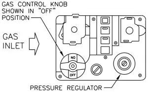
- Remove control access panel.
- Turn the gas control knob clockwise
 to the full “OFF” position, on the White Rodgers 36E push the knob before turning it.
 - “Wait five (5) minutes** to clear out any gas. Then smell for gas, including near the floor. If you smell gas, STOP! Follow “B” in the safety information
above (to the left) on this label. If you don’t smell gas, go to the next step.” - Turn the gas control knob counterclockwise
 to “ON”.
 - Replace control access panel.
- Turn on all electric power to the appliance.
- Set thermostat to desired setting.
- If the appliance will not operate, follow the instructions “TO TURN OFF GAS TO APPLIANCE” and call your service technician or gas supplier.
TO TURN OFF GAS TO APPLIANCE
- Turn off all electric power to the appliance.
- Set the thermostat to lowest setting.
- Remove control access panel.
- Push in gas control knob slightly and turn clockwise to “OFF”. Do not force.
- Replace control access panel.
BOILER SET UP
NOTE: Before starting the boiler, turn off the electrical supply going to it. Make sure that gas is available at the gas valve inlet. Open the valves in the return and supply piping. Failure to take these precautions will prevent the boiler from operation properly.
Fill the boiler and all of the radiation with water. Make sure that the system is completely purged of air.
Review these instructions and make sure that the boiler installation complies with ALL of the instructions up to this point.
BOILER OPERATION
WARNING: Before operating read and understand the instructions contained in this manual. Do not attempt to operate this boiler if it has not been installed in accordance with the guidelines set forth in this manual. Read and fully understand the operating instructions in the “For Your Safety Read Before Operating” section of this manual, pg 22 & 23. Failure to comply with this WARNING could result in a fire or explosion!
Should overheating occur or the gas supply fail to shut off, do not turn off or disconnect the electrical supply to the pump. Instead, shut off the gas supply at a location external to the appliance.
Do not use this appliance if any part has been under water. Immediately call a qualified service technician to inspect the appliance and to replace any part of the control system and any gas control that has been under water.
Direct Ignition System
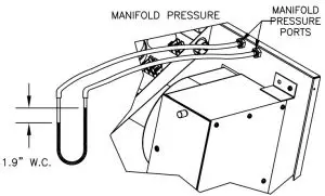
A. Connect a manometer to the pressure ports shown in Figure 20. Make sure that the gas supply piping has been purged of air and that all gas joints up to the gas valve have been thoroughly checked for leaks. Wait at least five minutes for any gas to dissipate before turning on the electrical power.
B. Read, understand and follow the operating instructions, on pg. 22 of this manual.
C. Raise the thermostat at least 5 degrees above the room temperature. A delay of about 30 seconds will take place as the silicon carbide ignitor heats up. Once the ignitor is hot, the main gas valve will open and the burner should light. If the burner fails to light the system will make two more ignition attempts. If the burner lights, but goes out within 4 seconds, the system will make three ignition attempts. If the burner has not lit after the last ignition try, the gas valve will close and the system will go into lock out. DO NOT attempt to reset the system until the ignition system has been inspected and the problem resolved. Once the problem has been resolved and 5 minutes have passed since the last ignition attempt, reset the system by turning the thermostat to it’s lowest setting and then back to where it was or by momentarily interrupting the electrical power to the boiler.
D. With the burner in operation the manometer should show 1.9″ W.C. manifold pressure. If not, see the BOILER CHECKING & ADJUSTMENT section. Close the manual shutoff valve in the gas supply line. As soon as the burner flame goes out, open the manual shutoff valve. A normal ignition sequence should take place.
E. With the burner in operation, interrupt the power to the control circuit by lowering and raising the thermostat. A normal ignition sequence should follow.
F. To test the ignition safety shutoff device, close the manual shutoff valve in the gas supply line. Within 6 seconds of main burner flame extinction, the main gas valve solenoid should close with an audible noise. The igniter should glow and make three attempts at ignition. After unsuccessfully attempting to light the burner the ignition module should lock out.
Open the manual shutoff valve in the gas supply line. Reset the ignition control system by interrupting, then restoring electrical power to the boiler. A normal ignition sequence should take place.
Figure 20- Air and Manifold Pressure
BOILER CHECKING and ADJUSTMENT
INPUT RATE
Gas appliances are rated based on sea level operation
with no adjustment required at elevations up to 2000
feet. At elevations above 2000 feet, input ratings should
be reduced by 4% for each 1000 feet above sea level.
Check the input rate as follows:
NATURAL GAS:
- Turn off all other gas appliances that use the same gas meter as the boiler.
- Call the gas company for the gas heating value. 3. Start the boiler and let it run for 15 minutes.
- Using the gas meter and a stopwatch, clock the time
that it takes to burn 10 cubic feet of gas and divide the time by 10. - Insert the heating value and the time, in seconds, into the formula below.
Input Rate = Heating Value(Btu/ft3 )(3600 s/hr)
Flow Rate(s/ft3 )
EXAMPLE: If the heating value = 1000 Btu/ft3
and the flow rate = 36 s/ft3
Input Rate = (1000 Btu/ft3 )(3600 s/hr)
36 s/ft3
Input Rate = 100,000 Btu/hr
If the computed rate deviates by more than 5% from the rated input value of the unit adjust the gas valve pressure accordingly. DO NOT adjust the manifold pressure by more than 5%. If a proper rate cannot be maintained without adjusting the manifold pressure beyond the 5% limit, the burner orifice must be replaced. If the input rate is too low go to the next larger size orifice. if the input rate is too high, go to the next smaller size orifice.
NATURAL GAS:
Optimum results are obtained when the boiler is operated at its full input rating, with 1.9″ W.C. of manifold pressure. The manifold pressure should not be more that 5% off this value. The gas valve pressure regulator has been preset at the factory. If adjustment is necessary the following steps must be followed:
- Connect each side of a manometer to the two pressure ports shown in Figure 20 to obtain the manifold pressure.
- Connect a flue gas analyzer to the vent pipe.
- Rotate the regulator adjustment screw clockwise to increase the manifold pressure, counterclockwise to decrease it. Never force the regulator adjustment screw or the gas valve will be damaged!
- The CO2 reading should fall between 7% and 9% with a CO reading of less than 50 ppm air free.
- Adjust the air damper using the screw on the front of the filter box if the CO2 and CO readings are not within the range given in step 4.
- Recheck the manifold pressure and adjust it if necessary.
- Replace the regulator adjustment screw cap and pressure port caps once the boiler is properly set up.
PROPANE GAS:
A manifold pressure of 1.9″ W.C. must be maintained for proper operation of the boiler. If the manifold pressure is off by more than 5% or if the CO2 and CO readings are not within the range specified in step 4 above, adjust it according to steps 1 through 7 above.
Main Burner Flame
A properly adjusted main burner flame will produce a tight blue flame pattern about 1/2 inch tall from the burner’s surface, Figure 21. A yellow floating or tall stringy flame is not normal and must be corrected.
WARNING: Yellow, floating flames indicate a lack of combustion air. DO NOT operate the boiler until the problem is solved or severe personal injury or death may occur!
Figure 21 – Burner Flame

TIGHT BLUE FLAME
YELLOW FLOATING FLAME
Thermostat Adjustment
Set the heat anticipator to 1.1 amps when controlling the boiler directly. For zoned systems set the heat anticipator to match the amp draw of the zone valves or pump relays.
BOILER MAINTENANCE
The boiler should be cleaned and inspected once a year, before each heating season. Refer to Figures 22 for component identification
CAUTION: Servicing, inspection and adjustment must be done by a trained technician in accordance with all applicable local and national codes. Improper servicing or adjustment could damage the boiler!
Control Panel
Use a soft brush and/or a vacuum cleaner to ensure that the electrical components are free from dust or deposits that would impair the boiler’s performance.
Air Filter
- Remove the front jacket panel.
- Remove the filter box cover and filter.
- Wash the filter in warm water. Shake out all excess moisture before reinstalling.
Burner Box Removal and Replacement
CAUTION: The burner box should not be removed! Careless handling can damage the burner.
WARNING: The ceramic combusiton chamber in the burner box and its gasket contain crystalline silica. Wear a tightly fitted dust mask when servicing the burner and gently handle the burner and its gasket to prevent inhalation of airborne fibers. Crystalline silica fibers have been identified as carcinogenic, or
possibly carcinogenic when inhaled.
If you suspect a problem within the burner assembly, please contact a local manufacturer representative.
Condensate System
Ensure that the condensate removal system is sound and working properly.
Vent System
The entire vent system must be thoroughly inspected for any signs of blockage, corrosion or leaks. Immediately replace any unsound vent system piping. Remove any foreign matter in or near the vent terminal or around the boiler that might obstruct the flow of combustion and ventilation air.
Blower Motor
Every 3 to 6 months, lubricate the inducer motor using 2 drops of 20W non detergent motor oil in each oil port.
Low Water Cutoff
If the boiler has been equipped with a low water cutoff device, follow the manufacturer’s instructions for cleaning and to confirm proper operation
Relief Valve
The relief valve should vent water when the test lever is lifted. It should not weep or discharge water at normal system pressure. NEVER try to clean or repair the relief valve! If the valve fails replace it!
Aquastat High Limit
The aquastat high limit controls the maximum water temperature in the boiler. It is adjustable from 140°F (60°C) to 220°F (104°C). If the water temperature reaches the set temperature before the demand for heat has been met, the aquastat high limit should shut the burners off. The outlet water temperature should never exceed 220°F (104°C). If the aquastat high limit fails to function properly replace it.
INSTRUCTIONS TO THE INSTALLER
The INSTALLER must give this copy of the INSTALLATION AND OPERATING INSTRUCTIONS to the boiler owner and make sure that the owner or operator has a basic understanding of the following:
- The operating instructions, the type of ignition system installed and how it operates.
- What the labels on the boiler say.
- How to start up and shut off the boiler.
- How to turn the gas and electrical power on or off.
- What to do if the boiler ignition system locks out.
- Where to check the system temperature and pressure and what they should be.
- The importance of reading, understanding and following these instructions.
- The importance of visually inspecting the vent system on a monthly basis.
The INSTALLER MUST make sure that the owner knows to shut the boiler off and call for service if the following conditions occur:
- Yellow lazy flames or flames outside the jacket.
- Gas smell or other strange odors.
- Discoloration of the boiler or surrounding materials.
- Water leaking from the heating system piping or relief valve.
- Flue products leaking from the vent system into the living space. Dampness or condensation in the building is a good indicator of this condition.
- The boiler’s flame rollout safety system is actuated.
- Control malfunction or sporadic operation.
Any appliance that burns natural gas, propane gas, fuel oil, wood or coal is capable of producing carbon monoxide (CO). Carbon Monoxide (CO) is a gas, which is odorless, colorless and tasteless but is very toxic. If your Smith boiler is not working properly, or is not vented properly, dangerous levels of CO may accumulate. CO is lighter than air and thus may travel throughout the building.
Any appliance that burns natural gas, propane gas, fuel oil, wood or coal is capable of producing carbon monoxide (CO). Carbon Monoxide (CO) is a gas, which is odorless, colorless and tasteless but is very toxic. If your Smith boiler is not working properly, or is not vented properly, dangerous levels of CO may accumulate. CO is lighter than air and thus may travel throughout the building.
Symptoms of CO poisoning include the following: Dizziness, vision problems, shortness of breath, headaches, loss of muscle control, unclear thinking, nausea, weakness and unconsciousness.
The symptoms of CO poisoning are often confused with those of influenza, and the highest incidence of poisoning occurs at the onset of cold weather or during flu season. A victim may not experience any symptoms, only one symptom, or a few symptoms. Suspect the presence of carbon monoxide if symptoms tend to disappear when you leave your home.
The following signs may indicate the presence of carbon monoxide:
- Hot gases from appliance, venting system, pipes or chimney, escaping into the living space.
- Flames coming out around the appliance.
- Yellow colored flames in the appliance.
- Stale or smelly air.
- The presence of soot or carbon in or around the appliance.
- Very high unexplained humidity inside the building.
If any of the symptoms of CO poisoning occur, or if any of the signs of carbon monoxide are present, VACATE THE PREMISES IMMEDIATELY AND CONTACT A QUALIFIED HEATING SERVICE COMPANY OR THE GAS COMPANY OR THE FIRE DEPARTMENT!
WARNING: Improper installation, adjustment, alteration, service or maintenance can cause property damage, personal injury exposure to hazardous materials or loss of life. Installation and service must be performed by a qualified installer, service agency or the gas supplier who must read and follow the supplied instructions before installing, servicing or removing this boiler. This boiler contains crystalline silica materials that have been identified as carcinogenic or possibly carcinogenic to humans when inhaled.
