1100-Lb. Single-Line/2200-Lb. Double-Line
Capacity Electric Hoist
Owner’s Manual
 WARNING: Read carefully and understand all ASSEMBLY AND OPERATION INSTRUCTIONS before operating. Failure to follow the safety rules and other basic safety precautions may result in serious personal injury. WARNING: Read carefully and understand all ASSEMBLY AND OPERATION INSTRUCTIONS before operating. Failure to follow the safety rules and other basic safety precautions may result in serious personal injury. |
Item #58925
READ & SAVE THESE INSTRUCTIONS
Thank you very much for choosing a Strongway™ product!
For future reference, complete the owner’s record below
Serial Number/Lot Date Code: ________________________________
Purchase Date: ____________________________________________
Save the receipt, warranty, and this manual. It is important that you read the entire manual to become familiar with this product before you begin using it.
This electric hoist is designed for certain applications only. Northern Tool and Equipment is not responsible for issues arising from modification or improper use of this product such as an application for which it was not designed. We strongly recommend that this product not be modified and/or used for any application other than that for which it was designed.
For technical questions, please call 1-800-222-5381.
Intended Use
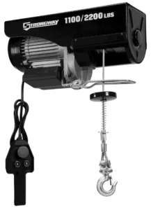
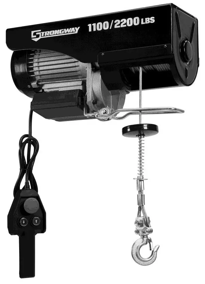
The Strongway 1100-Lb. Single-Line//2200-Lb. Double-Line Capacity Electric Hoist is a rugged, efficient 120V electric hoist that makes lifting easy. The hoist is ideal for lightweight jobs. For small jobs, it will be the ultimate labor-saving device. The hoist lifts up to 1,100 lb. with a single line or 2,200 lb. with a double line. Included is a swivel hook with an anti-twist 40 ft. x 0.22 in. diameter cable.
Packaging Contents
|
|
|
|
|
|
Technical Specifications
| Property | Specification |
| Voltage | 120V. 60Hz |
| HP | 2 |
| AMPS | 13.1 A |
| Loading Capacity | Single Line 1,100 lb. Double Line 2.200 lb. |
| Lifting Speed | Single Line 33 ft./min., Double Line: 16.5 ft./min. |
| Lifting Height | Single Line: 40 ft. Double Line: 20 ft. |
| Rope Diameter | 0.22 in. (5.6 mm) |
| Cable Tensile Strength | 1770 N/mmi |
| Duty Cycle (min) | 25%-10 min. |
| Net Weight | 66 lb. |
Important Safety Information
| ⚠WARNING |
|
| ⚠WARNING |
WORK AREA SAFETY
|
| ⚠WARNING |
PERSONAL SAFETY
|
| ⚠CAUTION |
HOIST USE AND CARE
|
Specific Operation Warnings
| ⚠WARNING |
|
Grounding
| ⚠WARNING |
|
Grounded Tools: Tools with 3-Prong Plugs
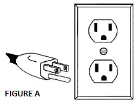
Tools marked with Grounding Required have a 3-wire cord and 3-prong grounding plug. The plug must be connected to a properly grounded outlet. If the tool should electrically malfunction or break down, grounding provides a low resistance path to carry electricity away from the user, reducing the risk of electric shock. (See Figure A.)
The grounding prong in the plug is connected through the green wire inside the cord to the grounding system in the tool. The green wire in the cord must be the only wire connected to the tool’s grounding system and must never be attached to an electrically live terminal.
Your tool must be plugged into an appropriate outlet, properly installed, and grounded in accordance with all codes and ordinances. The plug and outlet should look like those in the following illustration.

Double Insulated Tools: Tools with Two-Prong Plugs
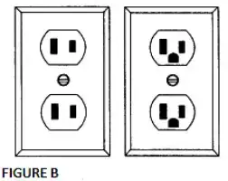
Tools marked Double Insulated do not require grounding. They have a special double insulation system that satisfies OSHA requirements and complies with the applicable standards of Underwriters Laboratories, Inc., the Canadian Standard Association, and the National Electrical Code. (See Figure B.)
Double insulated tools may be used in either of the 120-volt outlets shown in the following illustration.
Extension Cords
| ⚠WARNING |
|
- Grounded tools require a 3-wire extension cord. Double Insulated tools can use either a 2- or 3wire extension cord.
- As the distance from the supply outlet increases, you must use a heavier gauge extension cord.
Using extension cords with inadequately sized wire causes a serious drop in voltage, resulting in loss of power and possible tool damage. - The smaller the wire’s gauge number, the greater the capacity of the cord. For example, a 14gauge
the cord can carry a higher current than a 16-gauge cord. The minimum extension cord wire size is shown in the following table:
| Minimum Wire Size Of Extension Cords | ||||
| Nameplate AMPS | Cord Length | |||
| 25′ | 50′ | 100′ | 150′ | |
| 0-6 | 18AWG | 16AWG | 16AWG | 14AWG |
| 6-10 | 18AWG | 16AWG | 14AWG | 12AWG |
| 10-12 | 16AWG | 16AWG | 14AWG | 12AWG |
| 12-16 | 14 AWG | 12 AWG | NOT RECOMMENDED | |
- When using more than one extension cord to make up the total length, make sure each cord contains at least the minimum wire size required.
- If you are using one extension cord for more than one tool, add the nameplate amperes and use the sum to determine the required minimum cord size.
- If you are using an extension cord outdoors, make sure it is marked with the suffix W-A (W in Canada) to indicate it is acceptable for outdoor use.
- Make sure your extension cord is properly wired and in good electrical condition. Always replace a damaged extension cord or have it repaired by a qualified electrician before using it.
- Protect your extension cords from sharp objects, excessive heat, and damp or wet areas.
Main Parts of Hoist
| Subassembly |
| Electric Cable Hoist |
| Mounting Clamp |
| Lifting Hook |
| Pulley Hook |
| Hardware Bag |
Assembly Instructions
| ⚠WARNING |
|
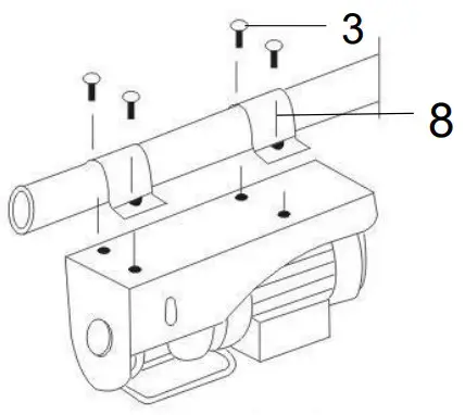
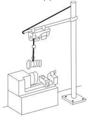
The hoist may be mounted on a secured overhead pipe or beam.
- Place the two hanging clamps (8) over the supporting structure where the hoist will be mounted.
Have a person or two help hold the hoist in position under the hanging clamps so the hoist is aligned with the holes in the hanging clamps.
- Tighten the screws (3) when the hoist is at a suitable position.
Before Each Use
| ⚠WARNING |
|
- Always inspect the wire cable for any wear, fraying, or damage. Only wire cable in good condition should be used. If the wire cable appears worn, frayed, or damaged, DO NOT connect any load to use, replace immediately.
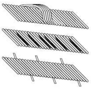
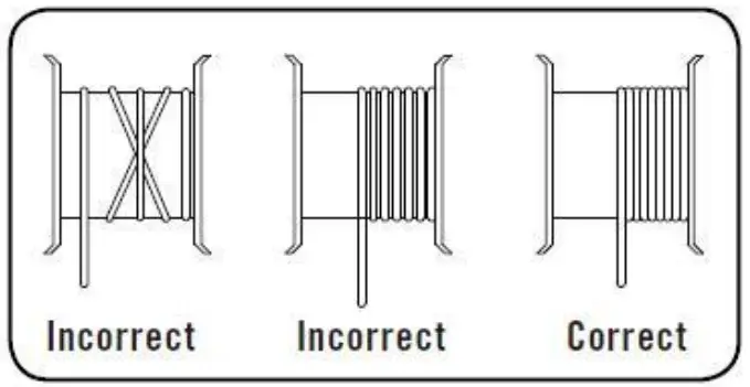
- Inspect the wire cable to make sure it is spooled correctly. The wire cable should not be overlapping on itself, have space between the rolls, or slack in it. If the wire cable is spooled incorrectly, DO NOT connect a load to it or use it until the wire cable has been re-spooled correctly.
Operating Instructions
| ⚠WARNING |
|
The electric hoist is rated at 1100 lb. for a single line and 2200 lb. for a double line capacity.
Single Line Operation
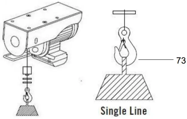
During single line operation, the max rated load capacity is 1100 lb. (500 kg). Do not exceed max rated load capacity. Single line loads can be connected with the support hook that comes already attached to the wire cable. The load can be directly connected to the support hook (73) using a properly rated hoisting sling, chain, or shackle. Make sure the load is directly underneath the hoist and is not at an angle.
Double Line Operation
During double line operation, the max rated load capacity is 2200 lb. Do not exceed the max-rated load capacity. Once the support hook is securely hooked into the double line support hole and the safety clasp has been fully clasped, the pulley hook can be attached to the wire cable. Follow these steps for attaching the pulley hook to the wire cable.
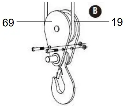
- Remove the washers (81), nuts (75 & 76), and bolts (71 & 72) from the pulley.
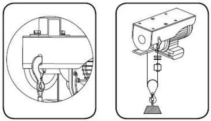
- Place the pulley hook assembly (69) (without the hook attached) onto the wire cable below the line blocker. Make sure the pulley hook roller is aligned on the wire cable (19) and is not in any way askew or oblongly seated on the wire.
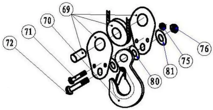
- Slide the bolt (71 & 72) back into the pulley (69), hook, and all washers (80 & 81). Finally, tighten the nuts (75 & 76). See the previous illustration.
Emergency Stop Switch
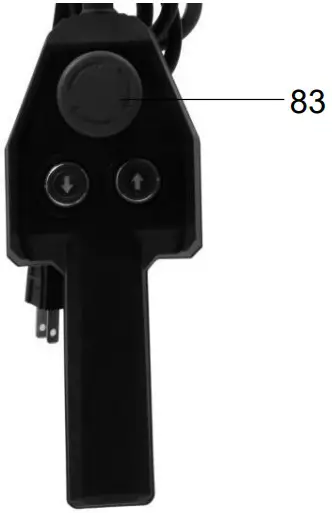
If an emergency occurs, press the emergency stop switch (83) immediately.
| ⚠WARNING |
| DO NOT store the wire rope where it can be of any harm. |
- Store the electric wire rope in a dry and clean place for future use.
- Lubricate the rope occasionally with light oil. Check that it is in good condition.
Maintenance
| ⚠WARNING |
|
Maintain the hoist by adopting a program of conscientious repair and maintenance in accordance with the following recommended procedures. It is recommended that the general condition of any tool be examined before it is used. Keep the hoist in good repair Keep handles dry, clean, and free from oil and grease. The following chart is based on a normal operating schedule.
| Maintenance Interval | Maintenance Point |
| Before operating | Inspect the hoist for good working condition. Check the condition of the electrical cords, plugs, and controls. Check to be sure the hoist is mounted properly. Make sure the bolts are tightened. |
| One month | Lubricate the rope occasionally with light oil. Periodically make sure the hoist limit switches function properly. |
Troubleshooting
| ⚠WARNING |
|
Use the table below to troubleshoot problems before contacting service personnel or your local dealer. If the problem continues after troubleshooting, call your local dealer for assistance.
| Failure | Possible Cause | Corrective Action |
| The hoist does not operate properly. | Fails to connect to the power. | Check that the plug is connected to the power. |
Parts Diagram
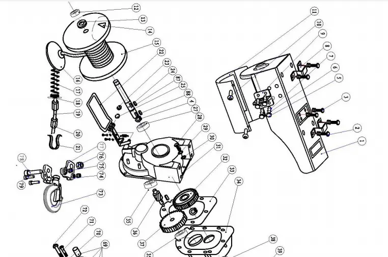
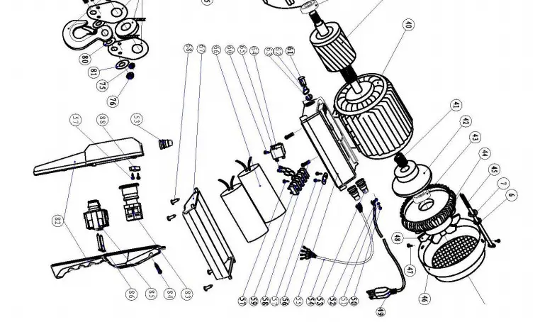
Parts List
| Reference | Part Description | Quantity |
| 1 | Housing | 1 |
| 2 | Screw Assembly (M12*30) | 4 |
| 3 | Screw (M10*26) | 4 |
| 4 | Circlip ø25 | 2 |
| 5 | Screw (M6*16) | 4 |
| 6 | Spring Washer ø6 | 4 |
| 7 | Washer ø6 | 4 |
| 8 | Fixing Ring | 2 |
| 9 | Hook Hole | 1 |
| 10 | Screw (M4*8) | 4 |
| 11 | Cover | 1 |
| 12 | Bearing | 1 |
| 13 | Washer | 1 |
| 14 | Rope Wedge | 1 |
| 15 | Rope Drum | 1 |
| 16 | Rope Block | 1 |
| 17 | Spring | 1 |
| 18 | Cushion Washers | 1 |
| 19 | Wire Rope | 1 |
| 20 | Rope Crimp | 2 |
| 21 | Rope Thimble | 1 |
| 22 | Limit Lever Assembly | 2 |
| 23 | Circlip ø8 | 1 |
| 24 | Drum Shaft | 1 |
| 25 | Washer ø8 | 1 |
| 26 | Key 8*20 | 1 |
| 27 | Bearing | 1 |
| 28 | Screw (M6*18) | 8 |
| 29 | Spring Washer ø6 | 6 |
| 30 | Washer ø6 | 6 |
| 31 | Gearbox | 1 |
| 32 | Secondary Gear | 1 |
| 33 | Gasket | 1 |
| 34 | Front Cover | 1 |
| 35 | Bearing | 2 |
| 36 | Middle Shaft | 1 |
| 37 | First Stage Gear | 1 |
| 38 | Bearing | 1 |
| 39 | Rotor | 1 |
| 40 | Stator Assembly | 1 |
| 41 | Spring | 1 |
| 42 | Brake Drum | 1 |
| 43 | Bearing | 1 |
| 44 | Motor Cover | 1 |
| 45 | Bolt | 4 |
| 46 | Fan Hood | 1 |
| 47 | Screw (M4*6) | 2 |
| 48 | Fan Blade | 1 |
| 49 | Power Cord | 1 |
| 50 | Screw (M4*8) | 1 |
| 51 | Spring Washer ø4 | 1 |
| 52 | Washer ø4 | 1 |
| 53 | Strain Relief Bushing | 4 |
| 54 | Cable | 1 |
| 55 | The base of Connection Box | 1 |
| 56 | Cable Pressure Plate | 2 |
| 57 | Screw | 4 |
| 58 | Screw Assembly (M4*12) | 4 |
| 59 | Terminal Block | 1 |
| 60 | Screw | 2 |
| 61 | Limit Switch Shaft | 1 |
| 62 | Switch Shaft Seal | 1 |
| 63 | Circlipø6 | 1 |
| 64 | Limit Switch | 1 |
| 65 | Quick-Connection 4.8 | 4 |
| 66 | Capacitor | 2 |
| 67 | Connection Box | 1 |
| 68 | Screw (ST 4.2*12) | 4 |
| 69 | Pulley Assembly | 1 |
| 70 | Hook | 1 |
| 71 | Screw (M5*35) | 2 |
| 72 | Screw (M12*45) | 1 |
| 73 | Hook | 2 |
| 74 | Washer ø5 | 2 |
| 75 | Nut M5 | 4 |
| 76 | Nut M10 | 2 |
| 77 | Hook Seat | 1 |
| 78 | Screw (M10*39) | 1 |
| 79 | Screw (M5*20) | 2 |
| 80 | Pulley Washer | 2 |
| 81 | Washer | 2 |
| 82 | Handle | 1 |
| 83 | Emergency Stop Switch | 1 |
| 84 | Screw (ST 4.2*18) | 5 |
| 85 | Switch | 1 |
| 86 | Screw (ST 4.2*45) | 2 |
| 87 | Key | 1 |
| 88 | Cable Pressure Plate | 1 |
Replacement Parts
- For replacement parts and technical questions, please call Customer Service at 1-800-222-5381.
- Not all product components are available for replacement. The illustrations provided are a convenient reference to the location and position of parts in the assembly sequence.
- When ordering parts, the following information will be required: item description, item model number, item serial number/item lot date code, and the replacement part reference number.
- The distributor reserves the right to make design changes and improvements to product lines and manuals without notice.
Limited Warranty
Northern Tool and Equipment Company, Inc. (“We” or “Us”) warrants to the original purchaser only (“You” or “Your”) that the Strongway product purchased will be free from material defects in both materials and workmanship, normal wear and tear excepted, for a period of one year from the date of purchase. The foregoing warranty is valid only if the installation and use of the product are strictly in accordance with product instructions. There are no other warranties, express or implied, including the warranty of merchantability or fitness for a particular purpose. If the product does not comply with this limited warranty, Your sole and exclusive remedy are that We will, at our sole option and within a commercially reasonable time, either replace the product or product component without charge to You or refund the urchase price (less shipping). This limited warranty is not transferable.
Limitations on the Warranty
This limited warranty does not cover: (a) normal wear and tear; (b) damage through abuse, neglect, misuse, or as a result of an accident or in any other manner; (c) damage from misapplication, overloading, or improper installation; (d) improper maintenance and repair; and (e) product alteration in any manner by anyone other than Us, with the sole exception of alterations made pursuant to product instructions and in a workmanlike manner.
Obligations of Purchaser
You must retain Your product purchase receipt to verify the date of purchase and that You are the original purchaser. To make a warranty claim, contact Us at 1-800-222-5381, identify the product by make and model number, and follow the claim instructions that will be provided. The product and the purchase receipt must be provided to Us in order to process Your warranty claim. Any returned product that is replaced or refunded by Us becomes our property. You will be responsible for return shipping costs or costs related to Your return visit to a retail store.
Remedy Limits
Product replacement or a refund of the purchase price is Your sole remedy under this limited warranty or any other warranty related to the product. We shall not be liable for: service or labor charges or damage to Your property incurred in removing or replacing the product; any damages, including, without limitation, damages to tangible personal property or personal injury, related to Your improper use, installation, or maintenance of the product or product component; or any indirect, inci ental or consequential damages of any kind for any reason.
Assumption of Risk
You acknowledge and agree that any use of the product for any purpose other than the specified use(s) stated in the product instructions is at Your own risk.
Governing Law
This limited warranty gives You specific legal rights, and You also may have other rights which vary from state to state. Some states do not allow limitations or exclusions on implied warranties or incidental or consequential damages, so the above limitations may not apply to You. This limited warranty is governed by the laws of the State of Minnesota, without regard to rules pertaining to conflicts of law. The state courts located in Dakota County, Minnesota shall have exclusive jurisdiction for any disputes relating to this warranty.

Distributed by:
Northern Tool & Equipment Company, IncBurnsville, Minnesota 55306
www.northerntool.com
Made in China