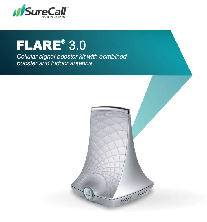
SureCall® FLARE® 3.0 User Guide
Cellular signal booster kit with combined booster and indoor antenna
04.02.2020
Introduction
Thank you for purchasing SureCall’s Flare 3.0 cellular signal booster kit. SureCall’s Flare 3.0 was specifically designed to eliminate frustrations over dropped calls and limited range by amplifying incoming and outgoing cellular signals in homes and offices.
If you have any questions during setup, please reach out to our US-based experienced support technicians:
Call: 1-888-365-6283
Email: [email protected]
Or, visit: www.surecall.com/support
![]() Watch installation, optimization and troubleshooting techniques
Watch installation, optimization and troubleshooting techniques

 Stay up to date with all things SureCall
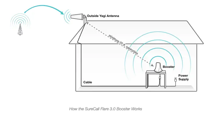
How It Works
- An outside antenna collects signal from the cell tower.
- The outside antenna sends the signal to the booster through coax cable.
- The booster amplifies the cell signal and rebroadcasts the signal indoors to all mobile devices within range.
- The booster amplifies outgoing cell signal back to the tower.

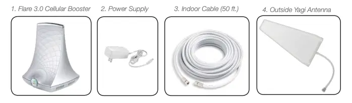
Package Contents
Unpack all package contents. For missing or damaged items, contact your reseller.
Turn over the signal booster and record the model and serial number for reference:
Serial #: ________________________________________________________________
Purchase Date: __________________________________________________________
Keep the carton and packing material to store the product in case you need to return. Your Flare 3.0 signal booster package includes the following items:
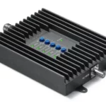
- SureCall Flare 3.0 signal booster
- Power supply
- Cable for connecting the outside antenna to the signal booster
- Outside Yagi antenna
Warning: Unauthorized antennas, cables, and/or coupling devices are prohibited by FCC new rules. Please contact FCC for details: 1-888-CALL-FCC. Changes or modifications not expressly approved by SureCall could void the user’s authority to operate the equipment.
Before Installation
- Prior to securing the location of any booster parts, a “soft install” is recommended as adjustments may be needed to optimize performance.
- Note that the outside antenna can be mounted to an exterior surface or a 1-2” diameter pole. A mounting pole is available separately (SC-J-Mount) . PVC piping from your local hardware can also be used.
- Your planned location for the booster (central to where signal is needed) should be near an existing electrical outlet.
- Ensure adequate separation between the planned locations of the booster and outside antenna (at least 25 ft.).
- Ensure sufficient cable length between the outside antenna location and booster location. The length of the provided cable is 50 ft.
Installation
Installation Overview
Step 1. Find the outside area with the strongest signal.
Step 2. Install the outside antenna
Step 3. Place the Flare 3.0 on a table or desktop, center of the area where signal is needed.
Step 4. Connect the booster to an AC power source.
Installation
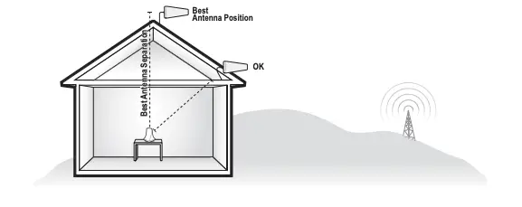
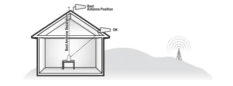
Step 1. Find the Area With the Strongest Signal
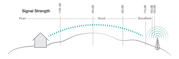
Using your phone, identify the outside location with the strongest signal for placement of your outside antenna. Generally, this is found above the roofline on the side facing your nearest cell tower and as high as possible – where the antenna can ‘see’ your cell tower. To find the location of your carrier’s closest cell tower, go to www.antennasearch.com.
The coverage area that the booster provides is directly related to the strength of incoming signal received by the outdoor antenna. Mounting the outside antenna where the signal is the strongest will provide the best results. Please note, if signal is extremely weak where the outside antenna is installed, indoor coverage will be limited.
Note that Bars are not always a reliable measure of signal. The best way to confirm signal coverage is the ability to place and hold a call.
Step 2. Install the Outside Antenna
After identifying the area of strongest signal, choose the surface where you will mount the outside antenna.
 Using the provided hardware, mount the outside antenna at the highest possible elevation, allowing a minimum separation of 25 feet from the planned location of the booster.
Once the outside antenna is secured, connect one end of the provided cable to the outside antenna and tighten the connection.
Do not collocate antennas or operate the outdoor antenna with any other antenna or signal booster.
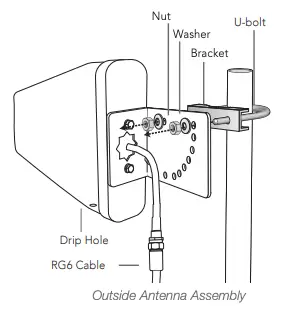
Outside Yagi Antenna Installation
Before installing a Yagi, or directional antenna, note that the antenna should be mounted on a pole or pipe (not provided), at the highest possible location and mounted horizontally, aimed in the direction of your nearest cell tower. To find the location of your carrier’s closest cell tower, go to www.antennasearch.com.
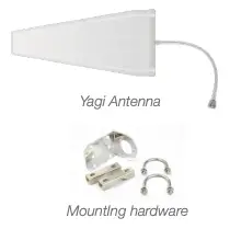 Ensure that the mounting area has at least a 12-inch radius clear of obstructions and other radiating elements and orient the antenna with the drip hole at the bottom.
Once you have identified your install location, assemble the u-bolt, bracket, nuts and washers onto a pole or pipe (not provided) as shown in the illustration. Keep the connections loose enough to allow the antenna to rotate until the optimum direction is found.
Once the outside antenna is secured to a pipe or pole, connect antenna to one end of the provided RG6 cable and tighten the connection. Run the cable along route to planned location of your booster.
Note: This booster is rated for 5-15V input voltage. DO NOT use the booster with a higher voltage power supply. This can damage the booster, cause personal injury, and void your warranty.
This booster should not be used near open fire or flame. Storage and transportation: Store and place in non-extreme room-temperature and dry environment.
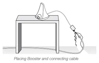
Step 3. Place the Booster
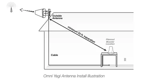 Place the booster in a central location where signal is needed and at least 25 ft. from the outdoor antenna location. When placing the booster, note that further separation between the booster and outside antenna will increase booster performance. Connect the open end of the RG6 cable from the outside antenna to the booster and tighten connection. Please note that the performance and range of your booster depends on three factors:
- Signal strength at the location of the outside antenna.
- Interior building materials between the booster and your mobile device.
- Distance between the outside antenna and booster (while at least 25 ft. separation is recommended, further separation will increase performance).
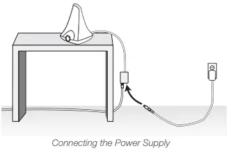
Step 4: Connect to Power
 Once the booster and outside antenna are connected and in place, connect the power cord to the signal booster and plug into a power outlet.
Enjoy Boosted Signal
Place a call in the room where the booster is located to confirm that your phone is receiving a boosted signal. Remember: Bars are not always a reliable measure of signal. The best way to confirm signal coverage is the ability to place and hold a call.
FCC 27.5 (d)(4): Fixed, mobile, and portable (hand-held) stations operating in the 1710-1755 MHz band as well as mobile and portable stations operating in the 1695- 1710 MHz and 1755-1780 MHz bands are limited to 1 watt EIRP.
Fixed stations operating in the 1710-1755 MHz band are limited to a maximum antenna height of 10 meters above ground.
IF YOU WANT TO IMPROVE PERFORMANCE
- Identify a location outside that receives a stronger signal and move the outside antenna to that location (higher is usually better).
- Increase the distance between the booster and outside antenna.
- See more tips and tricks or contact us at www.SureCall.com/support
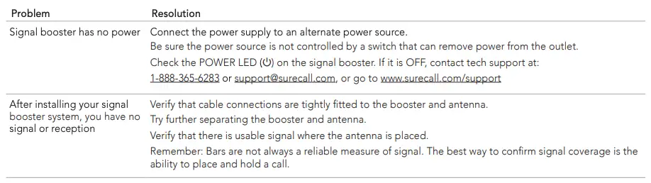
Troubleshooting
If you have any questions during setup, please reach out to our US-based experienced support technicians: Call: 1-888-365-6283, Email: [email protected], or Visit: www.surecall.com/support
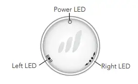
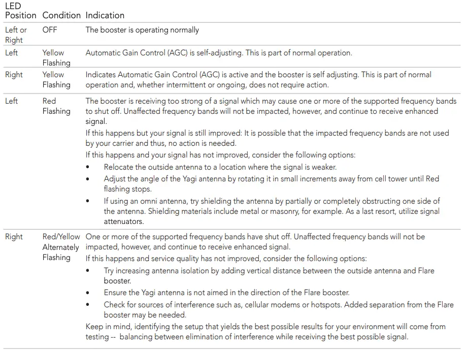
Booster LED Diagram
LED Indicators
NOTE: Normal operation is indicated by LEDs that are OFF -or- YELLOW Flashing. Only the presence of RED LEDs indicate potential need for adjustments.
Note that power cycling the booster after each adjustment may be necessary.
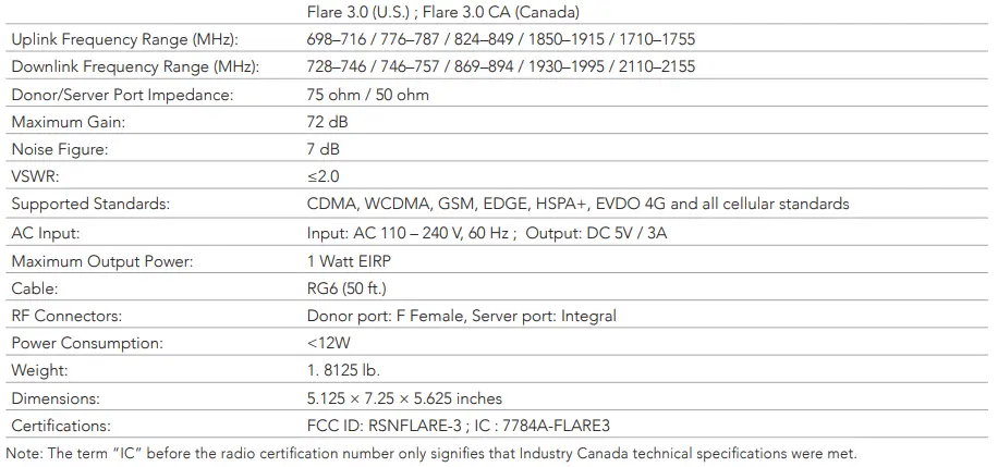
Specifications
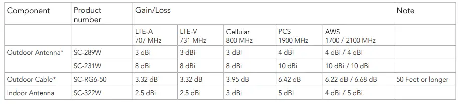
Kitting Information
*Note: The Flare 3.0 booster is suitable for use with all equivalent and lower gain antennas, as well as, equivalent or greater lengths of cable.
Kitting
Consumer Guidelines
This is a CONSUMER device
BEFORE USE, you MUST REGISTER THIS DEVICE with your wireless provider and have your provider’s consent. Most wireless providers consent to the use of signal boosters. Some providers may not consent to the use of this device on their network. If you are unsure, contact your provider.
In Canada, BEFORE USE you must meet all requirements set out in ISED CPC-2-1-051
You MUST operate this device with approved antennas and cables as specified by the manufacturer. Antennas MUST be installed at least 20 cm (8 inches) from (i.e. MUST NOT be installed within 20 cm of) any person.
You MUST cease operation of this device immediately if requested by the FCC (or ISED in Canada) or a licensed wireless service provider.
WARNING: E911 location information may not be provided or may be inaccurate for calls served by using this device.
This device may be operated ONLY in a fixed location, for in-building use.
Register your cellular booster with your wireless carrier at the following urls:
Verizon: http://www.verizonwireless.com/wcms/consumer/register-signal-booster.html
AT&T: https://securec45.securewebsession.com/attsignalbooster.com/
T-Mobile: https://support.t-mobile.com/docs/DOC-9827
Sprint: https://www.sprint.com/legal/fcc_boosters.html
U.S. Cellular: http://www.uscellular.com/uscellular/support/fcc-booster-registration.jsp
This device complies with Part 15 of FCC Rules. Operation is subject to the following two conditions: (1) this device may not cause harmful interference, and (2) this device must accept any interference received, including interference that may cause undesired operation.
CAN ICES-3 (B)/NMB-3(B) (Canada) :
This Class B digital apparatus meets all requirements of the Canadian Interference Causing Equipment Regulations. Operation is subject to the following two conditions: (1) this device may not cause harmful interference, and (2) this device must accept any interference received, including interference that may cause undesired operation
The Manufacturer’s rated output power of this equipment is for single carrier operation. For situations when multiple carrier signals are present, the rating would have to be reduced by 3.5 dB, especially where the output signal is re-radiated and can cause interference to adjacent band users. This power reduction is to be by means of input power or gain reduction and not by an attenuator at the output of the device.
1 For details on the requirements specified in ISED CPC-2-1-05, visit: http://www.ic.gc.ca/eic/site/smt-gst.nsf/eng/sf08942.html
SureCall, Inc
48346 Milmont Drive
Fremont, California 94538, USA
888.365.6283 | www.surecall.com