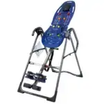
FitSpine XTM Series Assembly Instructions
Models X1, X2, X3
IMPORTANT SAFETY INSTRUCTIONS
READ ALL INSTRUCTIONS BEFORE USING THE INVERSION TABLE
WARNING
FAILURE TO FOLLOW INSTRUCTIONS AND WARNINGS COULD RESULT IN SERIOUS INJURY OR DEATH.
To reduce the risk of injury:
- Read and understand all the instructions, review all other accompanying documents, and inspect the equipment before using the inversion table. It is your responsibility to familiarize yourself with the proper use of this equipment and the inherent risks of inversion if these instructions are not followed, such as falling on your head or neck, pinching, entrapment, equipment failure, or aggravating a pre-existing medical condition. It is the responsibility of the owner to ensure that all users of the product are fully informed about the proper use of the equipment and all safety precautions.
- DO NOT use until approved by a licensed physician. Inversion is contraindicated in any medical or health condition that may be made more severe by an elevation of blood pressure, intracranial pressure or mechanical stress of the inverted position, or that may impact your ability to operate the equipment. This may include injury or illness, but also the side effects of any drug or supplement (prescribed or over-the-counter). Specific conditions may include, but not be limited to:
· Any condition, neurological or otherwise, which results in unexplained tingling, weakness or neuropathy, seizure, sleep disorder, light headedness, dizziness, disorientation, or fatigue, or impacts strength, mobility, alertness, or cognitive ability;
· Any brain condition, such as trauma, history of intracranial bleed, history or risk of TIA or stroke, or severe headaches;
· Any condition of the heart or circulatory system, such as high blood pressure, hypertension, increased risk of stroke, or use of anticoagulants (including high doses of aspirin);
· Any bone, skeletal or spinal cord condition or injury, such as significant spinal curvature, acutely swollen joints, osteoporosis, fractures, dislocations, medullary pins or surgically implanted orthopedic supports;
· Any eye, ear, nasal or balance condition, such as trauma, history of retinal detachment, glaucoma, optic hypertension, chronic sinusitis, middle or inner ear disease, motion sickness, or vertigo;
· Any digestive or internal condition, such as severe acid reflux, hiatal or other hernia, gallbladder or kidney disease;
· Any condition for which exercise is specifically directed, limited or prohibited by a physician, such as pregnancy, obesity, or recent surgery. - ALWAYS be certain the Ankle Lock System is properly adjusted and fully engaged, and that your ankles are secure before using the equipment. HEAR, FEEL, SEE and TEST that the Ankle Lock System is snug, close-fitting and secure EVERY TIME you use the equipment.
- ALWAYS wear securely tied lace-up shoes with a flat sole, such as a normal tennis-style shoe.
- DO NOT wear any footwear that could interfere with securing the Ankle Lock System, such as shoes with thick soles, boots, high-tops or any shoe that extends above the anklebone.
- DO NOT use the inversion table until it is adjusted properly for your height and body weight. Improper settings can cause rapid inversion or make returning upright difficult. New users, and users who are physically or mentally compromised, will require the assistance of a spotter. Make sure the equipment is set to your unique user settings prior to each use.
- DO NOT sit up or raise head to return upright. Instead, bend knees and slide your body to the foot-end of the inversion table to change weight distribution. If locked out in full inversion, follow the instructions for releasing from the locked position before returning upright.
- DO NOT continue using the equipment if you feel pain or become light-headed or dizzy while inverting. Immediately return to the upright position for recovery and eventual dismount.
- DO NOT use if you are over 6 ft 6 in (198 cm) or over 300 lbs. (136 kg). Structural failure could occur or head/neck may impact the floor during inversion.
- DO NOT allow children to use this machine. Keep children, bystanders, and pets away from machine while in use. The inversion table is not intended for use by persons with reduced physical, sensory or mental capabilities, unless they are given supervision and instruction concerning use of the machine by a person responsible for their safety.
DO NOT store the inversion table upright if children are present. Fold and lay the table on the floor. DO NOT store outdoors.
DO NOT use aggressive movements, or use weights, elastic bands, any other exercise or stretching device or non-Teeter® attachments while on the inversion table. Use the inversion table only for its intended use as described in this manual. - DO NOT drop or insert any object into any opening. Keep body parts, hair, loose clothing and jewelry clear of all moving parts.
- DO NOT use in any commercial, rental or institutional setting. This product is intended for indoor, home-use only.
- DO NOT operate equipment while under the influence of drugs, alcohol, or medication that may cause drowsiness or disorientation.
- ALWAYS inspect the equipment prior to use. Make sure all fasteners are secure.
- ALWAYS replace defective components immediately and/or keep the equipment out of use until repair.
- ALWAYS position equipment on a level surface and away from water or ledges that could lead to accidental immersion or falls.
- Refer to additional warning notices posted on the equipment. If a product label or Owner’s Manual should become lost, damaged or illegible, contact Customer Service for replacement.
Parts for Assembly
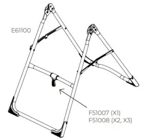
Stretch-and-Grip™ A-Frame Base Assembly
E61100 A-Frame
F51007 Angle Tether (X1) pre-assembled to A-Frame
F51008 EZ Angle Tether (X2, X3) pre-assembled to A-Frame
Handle Assembly
E61500 Stretch Assist™ Handles (2) (X1)
E61520 Stretch Max™ Handles (2) (X2, X3)
HK1008 Handle Assembly Hardware Kit
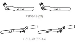
Roller Hinge Assembly
F51064B Roller Hinges (2) (X1)
TR1003B Roller Hinges w/ Traction Handles (2) (X2, X3)
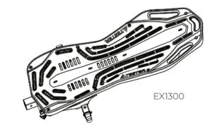
FitSpine™ Table Bed Assembly
EX1300 FitSpine™ Table Bed
HK1010 FitSpine™ Table Bed Hardware Kit
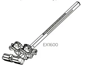
Main Shaft Assembly
EX1600 with T-Pin Ankle Lock System (X1)
EX1630 with EZ-Reach™ Ankle Lock System (X2)
EX1620 with Deluxe EZ-Reach™ Ankle Lock System (X3)
Optional Accessories
EX1800 Head Pillow
Tools Provided for Assembly
IA1149 5mm Allen Wrench (1)
EP1128A 6mm Allen Wrench (1)
F51088 Open-Ended Wrench (1)
Product Support
X1130 Owner’s Manual (X1)
X1230 Owner’s Manual (X2)
X1330 Owner’s Manual (X3)
Stretch-and-Grip™ A-Frame
Base Assembly with pre-assembled Angle Tether
FitSpine™ Table Bed Assembly
Use with Table Bed Hardware Kit (HK1010)
Optional Head Pillow

Handle Assembly
Use with Handle Assembly Hardware Kit (HK1008).

Roller Hinge Assembly
Main Shaft Assembly
T-Pin Ankle Lock System
(X1 Model Only)
EZ-Reach™ Ankle Lock System
(X2 Model Only)

Deluxe EZ-Reach™ Ankle Lock System
(X3 Model Only)

Tools Provided for Assembly
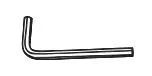 5mm Allen Wrench
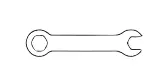
Open-Ended Wrench
 6mm Allen Wrench
Product Support
 Owner’s Manual
X1130 (X1)
X1230 (X2)
X1330 (X3)
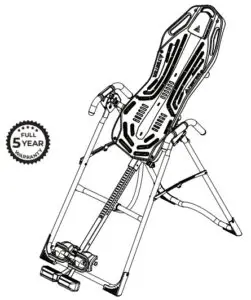
Understanding Your Inversion Table
Before reading further, study the drawing below to familiarize yourself with the important components of your Teeter Inversion Table.
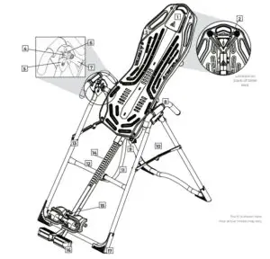
Identifying Parts and Components
- Head Pillow
- Upper Support Arms
- FitSpine™ Table Bed
- Pivot Pins
- Hinge Plates
- Self-Locking Hooks
- 3-Hole Roller Hinges
- Handles
- Height-Selector Locking Pin
- Spreader Arms
- Angle Tether
- Crossb
- A-Frame
- Main Shaft
- Ankle Lock System
- Ankle Comfort Dial™
- Non-Skid Stability Fee
Safety Warning Labels and Product Specifications
Please review all labels and supporting materials before using your inversion table.
This drawing indicates the locations of the warning labels found on your product. If a label is missing, illegible or is removed, contact Teeter Customer Service to request a complimentary replacement label.
Note: Image and labels below not shown at actual size.

Before Beginning Assembly
Unpack and Prepare Your Workspace
- If possible, assemble the equipment at or near the space in which you intend to use it to avoid moving it later.
- Unpack all parts and support materials. Set aside packing materials and clear your work area.
- Locate the Hardware Kits packaged with the manuals. They are labeled to correspond with the assembly process.
- The Getting Started Video Portal at teeter.com/videos provides step-by step instruction on how to assemble your product.
You may find it helpful to follow along with the videos by watching them on either your phone, tablet, or computer. The videos include important use instructions such as: - Assembly – Follow step-by-step instruction on how to assemble your Teeter
- User Settings – Personalize your inversion experience by adjusting four customization settings.
- How to Invert – Learn how to test your balance and rotation control, and how to properly invert and return upright.
- Dismounting – Learn how to properly dismount your Teeter according to your specific model.
- Storage & Maintenance – When not in use, store your Teeter easily and compactly.
- Dismounting – Learn how to properly dismount your Teeter according to your specific model.
- Accessories – Learn more about the accessories available for your Teeter.
STEP 1:
- On a level surface, position the A-Frame so that it is standing upright and the Stability Feet are on the ground.
- Gently push down on the Spreader Arms to ensure they are fully open and in the “locked” position (Figure 1).
- Look for temporary circular assembly assistance labels on the
A-Frame. RIGHT, LEFT, FRONT, and REAR indicate your position while using the equipment, not facing it. These labels can be removed easily upon completion of assembly. - Locate the Handle Assembly Hardware Kit (HK1008).
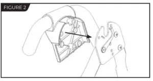
- Determine the left or right handles, marked with an embossed L / R on the inside of the black plastic part of each handle.
- Align the black plastic part of the corresponding handle (left / right) over the outside edge of the Hinge Plate on the A-Frame (Figure 2).
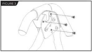
- Insert and loosely hand-tighten three of the Allen Head Screws through the Hinge Plate into the handle (Figure 3).
- Repeat with other handle. Tighten all fasteners with the 5mm Allen Wrench provided, being careful not to over-tighten.
- Proceed to Page 8 for Step 2.

STEP 2: Assemble Table Bed
- Locate the Table Bed Assembly Hardware Kit (HK1010).
- Place the Table Bed face down on the floor and push down on the Support Beam, so the two holes align evenly with the holes at the base of the Upper Support Arms (Figure 9). You may have to exert extra pressure to ensure that the Support Beam slides over the rubber spacers.
- Insert the two Bolts into the open holes (Figure 10).
- Thread a Washer and Nut onto each Bolt and hand-tighten.
- Using the 6mm Allen Wrench to steady the bolts, tighten the Nuts onto the Bolts with the 10/13mm Open-Ended Wrench.
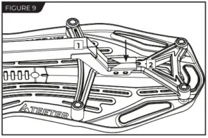
- Support Beam
- Upper Support Arms

STEP 3: Assemble Roller Hinges to Table Bed
NOTE: Some models come with Traction Handles pre-assembled to
the Roller Hinges. The assembly instructions detailed below still apply.
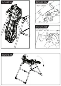
- For ease of assembly, rest the Table Bed against the Crossbar (Figure 12) at the front of the A-Frame.
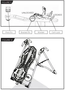
- On one side of the Table Bed, lift and hold the Cam Lock up all the way to unlock (Figure 13).
- In your other hand, hold one Roller Hinge near the Pivot Pin. With the Pivot Pin facing out (away from the Table Bed), slide the bottom of the Roller Hinge between the Cam Lock and the Bracket in the same direction as the arrow label located inside of the Cam Lock. TIP: Make sure that the Cam Lock is completely open when inserting the Roller Hinge, otherwise assembly will be more difficult.
- Engage one of the holes in the Roller Hinge over the Bracket Pin. Figure 13 shows the Roller Hinge installed correctly, with the Bracket Pin engaged in Setting C.
NOTE: Refer to the Owner’s Manual for an explanation of the hole settings. If you are unsure, use Setting C to start. - Push down on the Cam Lock (Figure 14) to lock it and secure the Roller Hinge.
- Repeat on other side. Make sure the Roller Hinges are in the same hole setting on both sides.

STEP 4: Assemble Table Bed to A-Frame
- Face the front of the A-Frame where the Crossbar is located (Figure 16).
- Grasp both Roller Hinges, right above the Cam Lock, and lift the
Table Bed. Allow the top of the Table Bed to rotate toward the floor, so that the back of the Table Bed is now facing you and the top of the Table Bed is in front of the Crossbar (Figure 17). - Lower each Roller Hinge Pivot Pin into the A-Frame hinge plates, one side at a time (Figure 16). The Self-Locking Hooks will open to allow the Pivot Pin into the Hinge Plate slot, then automatically snap closed over the Pivot Pin.
TIP: You may need to push outward on the Hinge Plate in order for
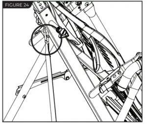
the second Pivot Pin to lock in place. - Make sure that each Pivot Pin is seated at the base of the slot in the Hinge Plates, and that the Self-Locking Hooks have closed over both Pivot Pins (Figures 18a & 18b).
WARNING: Failure of the Self-Locking Hooks to close over both Roller Hinge Pivot Pins is an indication of improper assembly and if not corrected could result in serious injury or death! - Rotate the Table Bed into the use position (Figure 19). Ensure that
it rotates smoothly. See also Image A on Page 13 to ensure
correct assembly

STEP 5: Assemble Main Shaft to Table Bed
- Your model’s Main Shaft may differ from what is shown in the figures, however the assembly instructions remain the same.
- Facing the front of the A-Frame, hold the Main Shaft in your left hand with the height markings facing up. Slide the end of the Main Shaft into the Main Shaft Housing (Figure 20), located at the base of the Table Bed.
- With your right hand, pull out the Height-Selector Locking Pin (Figure 19) to allow the Main Shaft to slide in further and release in the desired height setting. Refer to the Owner’s Manual for more information on selecting your height setting.
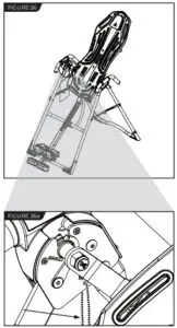
- The Main Shaft MUST REST against the Crossbar bumper on the A-Frame (Figure 22).
IMPORTANT: The Crossbar prevents the Table Bed from rotating forward when the user steps on the Ankle Comfort Dial. If the Main Shaft does not rest on the Crossbar bumper as shown in Figure 22, then the Table Bed has been assembled backwards onto the A-Frame.
This MUST BE CORRECTED before use. See also Image B on Page 13 to ensure correct assembly. - Test the inversion table by hand for smooth and steady rotation (Figure 23) and ensure that all fasteners are secure.

STEP 6: Attach Angle Tether & Head Pillow
Attach Angle Tether
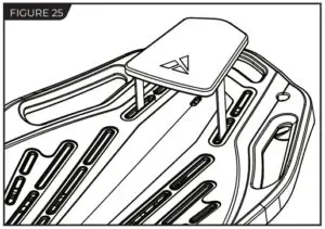
- The tether will come pre-assembled to the A-Frame.
- Unfold the adjustable tether and clip it to the U-Bar on the underside of the Table Bed (Figure 24).
- Slide the buckle to lengthen or shorten the strap depending on your desired maximum angle of inversion.

EZ-Angle Tether Accessory
Some models may come with the EZ-Angle Tether, embroidered with color-coded angle markers at 20° (GREEN), 40° (ORANGE), or 60° (RED). Simply slide the buckle so its center aligns with your desired color setting.
Attach Head Pillow
Attach the Head Pillow by securing the Velcro Straps through the specified holes in the Table Bed (Figure 25), which allow the pillow to shift with the user when in use. You may also customize the position depending on your preference.
Misassembly Check
Image A
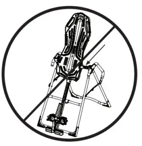
Go back to Step 3 for instruction. Demonstrates that the Roller Hinges have been assembled upside down into the Table Bed and must be corrected.
Image B
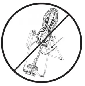
Go back to Step 4 for instruction. Demonstrates that the Table Bed has been assembled into the A-Frame backwards so the Main Shaft is not resting on the Crossbar and must be corrected.
Before Inverting
Ensure Owner’s Manual is Attached
The Owner’s Manual contains important information on how to use
your Teeter Inversion Table, including how to personalize the user
settings, properly secure and release the Ankle Lock System, and test
and adjust the rotation control.
- If not already attached, thread the provided metal chain through the pre-punched hole in the upper corner of the Owner’s Manual.
- Secure the chain to the A-Frame through the designated hole in the Hinge Plate (Figure 26 & 26a). Allow the Owner’s Manual to hang freely on the outside of the A-Frame Spreader Arms so it doesn’t interfere with the rotation of the Table Bed.
IMPORTANT: Once attached to the A-Frame, DO NOT remove the Owner’s Manual. It should remain permanently attached to your inversion table to serve as a reference for all users in regards to proper adjustment and use of the equipment.
WARNING
Read the Owner’s Manual thoroughly before using your Teeter Inversion Table. Improper settings could result in serious injury or death!
Watch the Getting Started Videos
The Getting Started Video Portal is a helpful supplement to the
Owner’s Manual, with easy-to-follow instructions on user settings,
how to invert, storage and maintenance, and even stretching and
exercises you can do with your Teeter. Just go to teeter.com/videos
to access them now
USA: Teeter
9713 233rd Avenue East
Bonney Lake, WA 98391
Toll Free: 800-847-0143
Fax: 800-847-0188
teeter.com | [email protected]