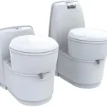
Refrigerator
N4000 Series
Instruction Manual

Introduction
This is the installation manual for the Thetford N4000 series refrigerator. The manual is meant for those installing the refrigerator in a mobile leisure vehicle. Read the information and instructions carefully and follow them strictly to install the refrigerator safely and correctly. Also read the warnings in the user manual before testing the refrigerator after installation. Our policy is one of continuous development and improvement. Specifications and illustrations may change subsequent to publication. For the latest version of this manual, please visit www.thetford.com.
 If the appliance is not installed in accordance with national and European regulations, rules and standards this will void the warranty.
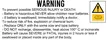
Symbols
Key to symbols:
Warning. Risk of injury and/or damage.
 Attention. Important information.
 Note. Additional information.
Regulations and standards
- Do not modify this appliance, unless the A modification is authorized and carried out by the manufacturer or their agent.
- Use only genuine and approved parts and materials.
- Wear the correct Personal Protective Equipment A during the installation.
- Also, follow the applicable safety regulations. Never expose the refrigerator to water or moisture.
- The performance of the refrigerator may be affected by adjacent heat sources such as an oven or stove.
- Protect the refrigerator against any heat sources by fitting insulation.
- Only a qualified person is allowed to install the refrigerator and its electrical and gas components.
- Install the refrigerator in accordance with local/ national laws.
- The electrical connections and gas components must be installed in accordance with the latest technical regulations.
- Incorrect installation or maintenance of the refrigerator may cause physical injury and/or damage to the refrigerator.
- The refrigerator must be sealed from the living area of the caravan or motor home according to EN 1949. Air for the burner ust not be drawn from the living area of the caravan or motor home and combustion gases must not enter the living area.
- To cool the system and to supply the burner with sufficient airflow, make sure that there is always sufficient ventilation through the outside vents.
- Pay close attention to current regulations on ventilation in the country of use. the installation must provide for adequate air supply for combustion to the burners, safe removal of combustion products and avoidance of accumulation of unburned gases.
- The gas pipe has to be installed free of tension.
- The refrigerator must be installed in a way that allows easy access for maintenance and repairs.
- Only a qualified installation person is allowed to maintain, remove or repair (electronic or gas components of) the refrigerator.
- Never use naked flames whilst performing maintenance or repairs on gas lines or when checking fittings for leaks. Gas may ignite and cause an explosion resulting in serious physical injury and/ or damage to the product.
- Never reposition or change the electronic or gas components or parts.
- The refrigerator only runs on liquid gas (propane, butane or a mixture of these both). It does not run on natural gas or coal gas.
- The fully installed refrigerator must allow proper and complete discharge of combustion gases. Combustion gases may contain carbon monoxide. Inhalation of this gas may cause tightness of the chest, dizziness and can lead to death.
- Combustion gases must always be discharged upwards.
- It is recommended to use an additional filter when operating on Liquefied Petroleum Gas (LPG).
- To avoid a hazard due to the instability of the appliance, it must be fixed in accordance with the instructions.
- Make sure the power plug is accessible so that the appliance can be disconnected from the supply after installation.
- If the supply cord is damaged, it must be replaced by the manufacturer, its service agent or similarly qualified persons in order to avoid a hazard.
- When positioning the appliance, ensure the supply cord is not trapped or damaged.
- Any error messages coming from refrigerator A should not disturb the driver. For example: flashing of the display to indicate an error while driving.
- Never open or damage the cooling system at the back of the refrigerator. The cooling system is pressurized and contains substances that can be harmful to your health.
Serviceability
The installer of Thetford products is responsible for proper installation to ensure the correct functionality and serviceability of the appliance. In terms of serviceability, this means that a dealer or an authorized Thetford service partner must be able to de-install and re-install the Thetford products within the time that is allowed according to the Thetford time-list, using standard tools and equipment.
This is to claim any warranty during the period of 3 years after the purchase date. In case of any queries on this subject, please contact the Thetford local service representative before installing the product
Position and placement
Use the mounting dimensions as shown below.
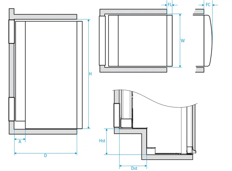
Table 1: Mounting dimensions
| Model | H’ | W | D | Hst | Dst | Fl | FC | A |
| N4080 | 825 | 487.5 | 530-570 | 209 | 186 | 43 | 130-170 | |
| N4090 | 825 | 526.5 | 530-570 | 209 | 186 | 43 | 130-170 | |
| N4097 | 825 | 526.5 | 530-570 | 209 | 186 | 78 | 130-170 | |
| N4100 | 825 | 526.5 | 530-570 | – | – | 43 | 130.170 | |
| N4104 | 825 | 526.5 | 530-570 | – | – | 78 | 130.170 | |
| N4108 | 825 | 526.5 | 580.620 | 209 | 186 | 43 | 130-170 | |
| N4112 | 825 | 526.5 | 580-620 | 209 | 186 | 78 | 130-170 | |
| N4141 | 1504 | 419.5 | 530-570 | 43 | 130-170 | |||
| N4142 | 1504 | 419.5 | 530-570 | 43 | 130-170 | |||
| N4145 | 1249 | 526.5 | 516-556 | 43 | 130-170 | |||
| N4150 | 1249 | 526.5 | 516-556 | 78 | 130-170 | |||
| N4170 | 1249 | 526.5 | 566-606 | 43 | 130-170 | |||
| N4170 | 1249 | 526.5 | 566-606 | 78 | 130-170 |
*Height is including feet (8mm), except for models N4141 and N4142. Models N4141 and N4142 have no feet. For these models, maintain a minimum distance of 12mm from the floor to prevent the door from scratching the floor.
Never lift or handle a refrigerator at the power supply cables.
Only small refrigerators: carry the refrigerator at the strap handles on top. Oo did not use your knee to lift the refrigerator.
■ Fixate the refrigerator with screws, using the predefined positions in the cabinet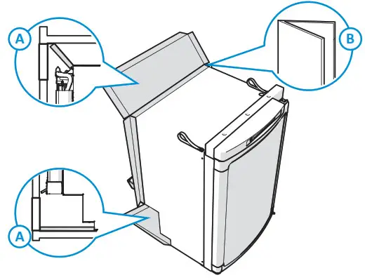 For flat door models, excluding N4080, there is also the possibility to build in the refrigerator in such a way that the refrigerator door is aligned with the front of the installation cabinet.
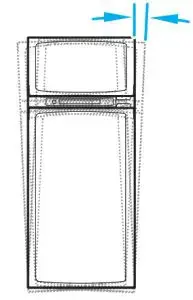
When a model N4141 or N4142 refrigerator is put next to a wall, it is important to keep a minimum distance of 15mm between the door and the wall, to be able to open the door completely.
Use the white caps for finishing.
For the models N4080, N4090, N4097, N4100, N4104, N4108 and For the models N4141, N4142, N4145.1.14150, N4170 and N4175, 6 screws and 6 white N4112, 4 screws and 4 white caps are supplied.
Do not screw into the refrigerator cabinet.
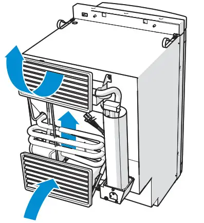
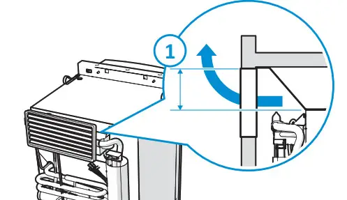
Combustion gasses will be extracted via the heat cap (1) through the upper vent. when installed properly.
For PVC tubes and/or water tubes within the sealing space, Thetford recommends using a heat shield or creating a minimum distance of 35mm (2) between heat cap and tubes.
- Place the refrigerator on a flat and stable floor.
- For optimum performance, the refrigerator must be level. Performance is still guaranteed within the limit of ±2.5 degrees.
 Notice that the tilt of the chassis or floor can already be a few degrees.
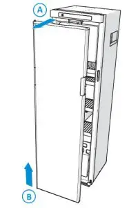
- Make sure the refrigerator is sealed from the living
- As an example how to do this: apply strips to the rear and sides (B) of the refrigerator and fix the upper and lower flap (A) of the combustion selling.
Connecting gas and electrical supplies
The refrigerator is designed for powering by liquid gas (propane, butane or a mixture of these both), 12V OC or 230V AC. These are the values of the gas and electrical supplies.
Install the electrical and gas connections in such a way that wires cant come into contact with hot or sharp Parts.
Table 2: Gas
| Category | C11 |
| Gas type | 13, (G30: 28-30/G31: 3? mbar) for BE, FR, El, LU, PT, ES, GB, GR, IT 1303p (630/G31: 28-30 mbar) for DK, DE, IS, NL, SE, F1, NO Butane = G30 / Propane = G31 |
| Diameter gas tube | 8mm |
| Gas pressure | See the serial label inside the refrigerator (behind the vegetable bin or on the left side underneath the freezer) for pressure settings of the gas pressure control |
Table 3: AC
| AC | 230V |
| Operating window | 210-250V/50-60Hz |
| Fuse | 2A slow |
Due to sophisticated AC regulation, it is difficult to perform a power measurement.
It is obligated to connect the AC wiring to a properly earthed powerpoint.
Table 4: DC
| DC | 12V |
| Power requirement 12V high current | 12V- 14.4V at the fridge (when 12V heaters are enabled) |
| Cable dimensions (Cable thickness vs cable length) | ■ 4mm2 = > 2.5m ■ 6mm2 = > 3.5m ■ lOmm2 = > 6m |
| Fuse high-current | 25A |
| High current supply | red cable (+) and white cable (-) for heating element. Only switched if signal on 0+ |
| Fuse low-current | 1.1A |
| Low current supply | purple (+) and black (-) for electronics |
| D+ signal | orange + when the engine runs |
| If 0+ signal is not present on the vehicle | No cooling on DC/12V. Possible solution: bridge D+ with LC+ |
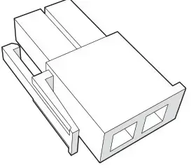
Table 5: Connector Plug
| Connector plug (on the refrigerator) | Connector plug (counterpart |
| ■ STOCKO VV2028.110 G PA6 V2 ■ Cable length: 250 mm |
■ TE 880297-1, or any other equivalent |
 |
 |
The bridge 0+ with LC+ can drain the battery when cooling on DC/12V while the engine is not running.
2-way option
When the 2-way option is connected, the 12V DC power supply will be deactivated and only the gas and AC power supply are available. To use the 2-way option, connect the wiring according to this diagram.
 12V connector to the Power Control Board (provided by Thetford)
- Build a cable bridge (to be done by a certified dealer)
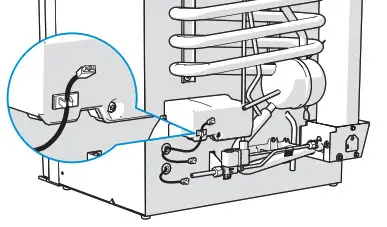
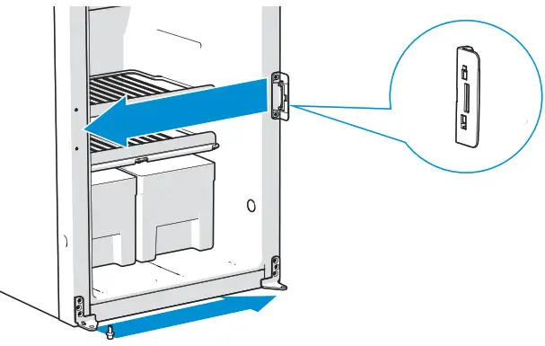
Connection points
The connection points for gas and electricity are located at the rear of the refrigerator.
- Electricity connection point
- Gas connection point
Connect an 8mm gas tube to the gas connecting point of the refrigerator.
Never use rubber tubing.
For detailed information about the type and dimensions of the inlet of the gas tube, technical drawings are available on request.
- Connect the AC and DC power supply according to this diagram.
For detailed information about the type of connectors, technical drawings are available on request.
Connectivity
To connect the refrigerator to the compatible central control board of the vehicle, use the Cl-bus protocol (please refer towww.civd.de).
Any error messages coming from the refrigerator and shown on the master display, should not disturb the driver. For example lights and/or sounds coming from the master display while driving.
There is no load dump protection circuit present on the Cl-bus refrigerator electronics. Thetford requires that a load dump circuit (which complies with the relevant regulations) is installed on the Cl-bus master if the refrigerator is connected to the Cl-bus.
The Cl-bus connection point is located at the rear of the refrigerator:
Do not use the Cl-bus cable clip to guide any other cables than the Cl-bus connector cable.
Table 6: Cl-bus connectors
| CI-bus connector plug on the refrigerator | Cl-bus connector plug counter part |
| ■ Mini-Fit Jr. connector (male) supplier Molex, P/N 39012020 ■ Cable length: 90 mm |
■ Mini-Fit Jr. Mini-Fit Jr. connector (female) supplier Molex, P/N 39012021 |
 |
 |
The Cl-bus Connection is not available for models with a battery pack.
Installing vents
The refrigerator performance depends on good ventilation through two vents in the wall of the vehicle. Cold air comes in through the lower vent, passes the cooling unit and leaves hot through the upper vent.
 Use the proper vents for your refrigerator model. The correct measurements are shown in Table.
Table 7: Vent size.
| Model | 186 x 483mm | 257 x 432mm | 281 x 523mm |
| N4080 | X | – | – |
| N4090 | X | – | – |
| N4097 | X | – | – |
| N4100 | X | – | – |
| N4104 | X | – | – |
| N4108 | X | – | |
| N4112 | X | – | |
| N4141 | – | X | – |
| N4142 | – | X | – |
| N4145 | – | – | X |
| N4150 | – | – | X |
| N4170 | – | X | |
| N4175 | – | – | X |
You can buy vents at an authorized local Service Centre. For further instructions, see the installation instructions of the vents.
The recommended installation is when the vents are not covered.
 Make sure that combustion gases can not enter the living area.
 When the installation is next to the caravan door, make sure that there will be at least a 25mm distance between the vents and the door.
- Min. 25mm
Make sure vents cannot be blocked by the door or other objects. An insufficient air supply can result in incomplete combustion, the forming of carbon monoxide, and a reduction of cooling performance.
- Install the upper vent in the wall of the vehicle at the top of the refrigerator.

- Vent size 186 x 483mm: Min. 110mm
Vent size 257 x 432mm: Min. 135mm
Vent size 281 x 523mm: Min. 175mm
- Install the lower vent in the wall of the vehicle on the floor level behind the power board.
If the lower vent is not on floor level, make sure all unburned gas will go to the outside (for example via a hole in the floor).
This vent is also used for periodical maintenance or repairs of the refrigerator.
Door conversion
Only for N4141/N4142
Images may differ from your model.
- Open the door a little and remove the hinge pin.

- Lift the door out the hinges

- Move the lock on the refrigerator from one side to the other.

- Move the hinges,handle, hinge pin and hinge hole plug from one side to the other on the door.

After installation
- Ensure that all packaging materials have been removed.
- Test all gas piping and connections and make sure they do not leak.
- Check all electrical connections.
- Check if the sealing has been applied correctly.
- Check if the vegetable bins can be removed from the appliance.
- Check if the door can be closed correctly.
- Check for correct operation.
Technical Specifications
Table 8: Refrigerator Specifications
| Model | Display | Gross volume (L) | Total volume (L) | Volume frozen food comp. L | Energy con- assumption (kWh/24h) | Energy consumption gas (g/24h) | Net weight (kg) |
| N4080 | LED+ | 81 | 71 | 10 | 2.6 | 270 | 22.5 |
| N4090 | LED+ or LCD | 89 | 78 | 11 | 2.9 | 300 | 22.5 |
| N4097 | LED+ or LCD | 96 | 86 | 11 | 2.9 | 300 | 23.5
I |
| N4100 | LED+ or LCD | 97 | 86 | 11 | 2.8 | 330 | 27 |
| N4104 | LED+ or LCD | 105 | 94 | 11 | 2.8 | 330 | 27 |
| N4108 | LED+ or LCD | 106 | 90 | 11 | 2.9 | 300 | 24 |
| N4112 | LED+ or LCD | 113 | 98 | 11 | 2.9 | 300 | 24 |
| N4141 | LED+ or LCD | 141 | 135 | 15 | 4.5 | 468 | 38 |
| N4142 | LED+ or LCD | 142 | 137 | 15 | 4.5 | 468 | 37 |
| N4145 | LED+ or LCD | 141 | 136 | 26 | 4.3 | 437 | 37 |
| N4150 | LED+ or LCD | 149 | 145 | 27 | 4.3 | 437 | 37.5 |
| N4170 | LED+ or LCD | 167 | 1S6 | 29 | 4.3 | 437 | 39 |
| N4175 | LED+ or LCO | 175 | 165 | 31 | 4.3 | 437 | 39.5 |
Above volumes and energy consumption has been calculated according to IEC 62552-3:2020.
Servicing
All servicing must be carried out by an authorized person. Before any service work is started, the appliance must be disconnected from both the gas and the electrical supplies. After each service, the appliance must be checked for gas soundness and must be sealed from the living area. For service, please contact your authorized local Service Centre giving details of the model and serial number on the data badge plus date of purchase.

Questions/customer service
- Visit www.thetford.com.
- Contact Customer Service Thetford in your country. See the addresses on the back
| EUROPEAN HEADQUARTERS Thetford B.V. Nijverheidsweg 29 P.O. Box 169 4870 AD Etten-Leur The Netherlands |
UNITED KINGDOM Thetford Ltd. Unit 6 Brookfields Way Manvers, Rotherham S63 5DL, England United Kin!dom |