INVERTER TIG DC
WELDER(MOS)
TIG-SERIES OWNER’S MANUAL
PLEASE READ THOROUGHLY
BEFORE OPERATING THIS MACHINE
SECTION 1 SAFETY PRECAUTIONS FOR SERVICING
1-1. Symbol Usage
 Means Warning! Watch Out! There are possible hazards with this procedure! The possible hazards are shown in the adjoining symbols.
 It Marks a special safety message.
 Means “Note”; not safety-related.

This group of symbols means Warning! Watch Out for possible ELECTRIC SHOCK, MOVING PARTS, and HOT PARTS hazards. Consult symbols and related instructions below for necessary actions to avoid the hazards
1-2. Servicing Hazards
- The symbols shown below are used throughout this manual to call attention to and identify possible hazards. When you see the symbol, watch out, and follow the related instructions to avoid the hazard.
- Only qualified persons should service, test, maintain, and repair this unit.
- During servicing, keep everybody, especially children, away.
 ELECTRIC SHOCK can kill.
- Do not touch live electrical parts.
- Turn Off welding power source and wire feeder and disconnect and lockout input Power using
- Line disconnect switch, circuit breakers, or by removing the plug from the receptacle, or stop engine before servicing unless the procedure specifically requires an energized unit.
- Insulate yourself from the ground by standing or working on dry insulating mats big enough to prevent contact with the ground.
- Do not leave the live unit unattended.
- If this procedure requires an energized unit, have only personnel familiar with and following standard safety practices do the job.
- When testing a live unit, use the one-hand method. Do not put both hands inside the unit. Keep one hand free.
- Disconnect input power conductors from a de-energized supply line BEFORE moving a welding power source.
- SIGNIFICANT DC VOLTAGE exists after removal of input power on inverters.
- Turn Off the inverter, disconnect input power, and discharge input capacitors according to instructions in Maintenance Section before touching any parts.
 STATIC (ESD) can damage PC boards.
- Put on grounded wrist strap BEFORE handling boards or parts.
- Use proper static-proof bags and boxes to store, move, or ship PC boards.
 FIRE OR EXPLOSION hazard.
- Do not place the unit on, over, or near combustible surfaces.
- Do not service unit near flammables
 FLYING METAL can injure the eyes
- Wear safety glasses with side shields or face shields during servicing.
- Be careful not to short metal tools, parts, or wires together during testing and servicing.
 HOT PARTS can cause severe burns.
- Do not touch hot parts bare-handed.
- Allow cooling period before working on welding gun or torch
 MAGNETIC FIELDS can affect pacemakers.
- Pacemaker wearers keep away from servicing areas until consulting your doctor.
 EXPLODING PARTS can cause injury.
- Failed parts can explode cause other parts to explode when power is applied to inverters.
- Always wear a face shield and long sleeves when servicing inverters.
 SHOCK HAZARD from testing.
- Turn Off the welding power source and wire feeder or stop the engine before making or changing meter lead connections.
- Use at least a one-meter lead that has a self- retaining spring clip such as an alligator clip.
- Read instructions for test equipment.
 FALLING UNIT can cause injury.
- Use lifting eye to lift unit only, NOT running gear, gas cylinders, or any other accessories.
- Use equipment of adequate capacity to lift and support the unit.
- If using lift forks to move the unit, be sure forks are long enough to extend beyond the opposite sides of the unit
 MOVING PARTS can cause injury.
- Keep away from moving parts such as fans.
- Keep all doors, panels, covers, and guards closed and securely in place.
 MOVING PARTS can cause injury.
- Keep away from moving parts
- Keep away from pinch points such as drive rolls
 OVERUSE can cause OVERHEATING.
- Allow cooling period; follow rated duty cycle.
- Reduce current or reduce duty cycle before starting to weld again.
- Do not block or filter airflow to the unit.
 H.F. RADIATION can cause interference.
- High-frequency (H.F.) can interfere with radio navigation, safety services, computers, and communications equipment.
- Have only qualified persons familiar with electronic equipment install, test, and service
- H.F. producing units.
- The user is responsible for having a qualified electrician promptly correct any interference problem resulting from the installation.
- If notified by the FCC about interference, stop using the equipment at once.
- Have the installation regularly checked and maintained.
- Keep high-frequency source doors and panels tightly shut, keep spark gaps at the correct setting, and use grounding and shielding to minimize the possibility of interference.
 READ INSTRUCTIONS.
- Consult the Owner’s Manual for welding safety precautions.
- Use only genuine replacement parts
1-3. EMF Information
Considerations About Welding And The Effects Of Low-Frequency Electric And Magnetic Fields
Welding current, as it flows through welding cables, will cause electromagnetic fields. There has been and still is some concern about such
fields. However, after examining more than 500 studies spanning 17 years of research, a special blue-ribbon committee of the National Research Council concluded that: “The body of evidence, in the committee’s judgment, has not demonstrated that exposure to power-frequency electric and magnetic fields is a human-health hazard.” However, studies are still going forth and evidence continues to be examined. Until the final conclusions of the research are reached, you may wish to minimize your exposure to electromagnetic fields when welding or cutting. To reduce magnetic fields in the workplace, use the following procedures:
- Keep cables close together by twisting or taping them.
- Arrange cables to one side and away from the operator.
- Do not coil or drape cables around your body.
- Keep welding power source and cables as far away from operator as practical.
- Connect the work clamp to the workpiece as close to the weld as possible.
About Pacemakers:
Pacemaker wearers consult your doctor first. If cleared by your doctor, then following the above procedures is recommended
SECTION 2 INSTALLATIONS
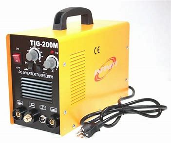
2-1. Welding power source TIG POWER SOURCE
| Type | TIG-250 | TIG-250 |
| Power AND Frequency |
AC220V ± 10% 50/60Hz |
AC220V/380 50/60Hz |
| Input current | 20A | 12A/11A |
| Phase | 1PH | 1PH |
| Rated input(KVA) | 4.2 | 2.7/4.2 |
| Amperage range(A) | 5-190A | 5-140A/5-190A |
| Open circuit voltage(V) | 56V | 52V |
| Rated working voltage(V) | 17.6V | 15.6/17.6V |
| Efficiency (%) | 85 | 85 |
| Duty cycle (%) | 60 | 60 |
| Power factor | 0.93 | 0.93 |
| Insulation Grass | F | F |
| Weight (kg) | 8.5 | 8.5 |
| Dimension (L x W x H) MM) | 435*162335 | 435*162*335 |
 CAUTION
WELDING A LONGER THAN RATED DUTY CYCLE CAN DAMAGE THE TORCH AND VOID THE WARRANTY.
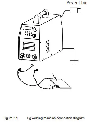
2-2. Connection diagram

2-3. Install procedure
2-3.1 Welding machine should be installed in a stable position and with good ventilation. Avoid direct sun outdoors. Avoid transport in invert or side position.
2-3.2 Connect electrode holder, earth cable, according to the connection diagram.
2-3.3 Set welding current according to Table 2.2
2-3.4 Use Ф8 heat-resistant PVC hose to connect the flow meter with the gas connection nipple at the rear of the machine.
2-3.5 Commission the machine after the machine is installed and tested.
Recommend welding parameter
The settings listed below are just for the initial commission of the machine. The parameters can be refined in actual cutting.
Welding Parameters
| Thickness (mm) | Welding current of various Materials (A) | Welding speed (cm/min) | Diameter of wire (mm) | Diameter of
tungsten electrode (mm) |
Gas
flux (I/min) |
|||
| Stainless steel | Al | Copper | Brass | |||||
| 0.8-1.0 | 30-50 | 20-50 | 40-65 | 30-50 | 20-30 | 0-1 | 1-1.6 | 5-6 |
| 1.2-2.0 | 60-100 | 30-80 | 50-120 | 50-90 | 20-25 | 1.2-2.5 | 1.6-2 | 6-7 |
| 2.5-3.0 | 110-160 | 120-160 | 130-200 | 110-160 | 15-25 | 2.5-4 | 2-2.4 | 7-8 |
| 4.0-4.5 | 170-220 | 170-240 | 220-300 | 200-250 | 15-20 | 6.0 | 3.2-4 | 10-12 |
| 8.0-10.0 | 240-300 | 300-380 | 350-430 | 240-330 | 10-12 | 6.0 | 3.2-4 | 10-12 |
| ≥ 12 | ≥300 | ≥400 | ≥500 | ≥300 | 10-12 | 6.0 | ≥4.8 | 12-15 |
SECTION 3 OPERATION
3-1 Front panel Layout
| 1、O.C LED 4、Continuous 7、Switch button 10、OUT+ 13、The caller 16、Storage 19、After the gas 22、The base value current 25、Duty ratio 28、Ground wire 31、power switch |
2、A single 5、Cold welding 8、The gun switch 11、 Switch button 14、Call 17、DC 20、Gap time 23、Frequency 26、Before the gas 29、Fan 32、Gas input |
3、TIG 6、Switch button 9、Welding torch interface 12、Encoder regulation 15、Pulse 18、The menu button 21、Welding time 24、Welding current 27、According to the table 30、Power input |
Figure 3.1
3-2 Operation
ACCORDING THE MACHINE TYPE USE POWER SUPPLY.
3-2.1 The boot defaults to the welding state before the last shutdown.
3-2.2 Welding process selection, according to the process requirements to choose argon arc welding or cold welding. In general, cold welding is recommended for sheet metal under 0.8mm.
3-2.3 ingle and continuous function is used in cold welding process state, single state, press the gun switch within a fixed time (more than 30) welding, whether or not to loosen the gun switch will stop welding, continuous welding state, press the gun into the welding state, loosen has been intermittent spot welding, press the gun switch again, welding stop. The interval time and welding time can be adjusted as needed under menu 5.
3-2.4 Dc or pulse function can only be selected in the state of argon arc welding. Dc can adjust the time and welding current of forward gas and back gas through the menu key 5. In the state of impulse, forward gas and back gas time, duty cycle, frequency, base value and welding current parameters can be adjusted through the menu key 5.
3-2.5 Use of the storage call key: after configuring various parameters, press the no. 4 key for 3 seconds and the storage light is on. Rotate the digital tube 7 of the encoder to display p01-p10. If you press the number 4 key once and the call light is on, rotate the encoder number 6 to select the parameters under the number stored before the call.
3-2.6 Menu key for selecting process parameters and fine-tuning through encoder.
 CAUTION
3-2.7 GRINDING THE TUNGSTEN ELECTRODE PRODUCES DUST AND FLYING SPARKS WHICH CAN CAUSE INJURY AND START FIRES.USE LOCAL EXHAUST AT THE GRINDER OR WEAR AN APPROVED RESPIRATOR
SECTION 4 TROUBLESHOOTING
| Problem | Cause | Solution |
| The cutter irresponsive after pushing the torch switch’ |
1. The switch or control cables broken. 2.Control transformer broken. |
Replace or connect Replace |
| The working indicator light brighten at all time |
1.The switch short circuit 2.The switch terminal short circuit | Replace The switch terminal insulated again |
| The covers creepage |
1.The power supply leads to connect with covers 2.The transformer connects with covers 3.The covers no or poor contact earth |
The power supply leads to insulated The contact part insulated The covers should be earth reliably |
| Failure of arc to ignite with high frequency |
1.The torch cable open circuit 2.The spark gap too little 3.The earth leads or torch cable poor contact 4.There is lacking in power phase 5.There is air compressor or reductor |
Connect Adjust the distance Connect Connect |
| The workpiece poor penetration |
1.Beyond the rated welding range 2.The torch incline angle is bigger 3.The Ar compressor pressure is out of the range |
Replace the high power welder Adjust the angle Adjust the pressure |
| The arc extinguish suddenly while welding | 1.The cutting speed is too slow 2.The torch poor contact on the workpiece 3. The tungsten needle are broken |
Adjust the interval between the torch and the workpiece Replace the tungsten needle |
Table 4.1
If you are unable to fix the problem with your welding machine by following this basic troubleshooting guide or if you need further assistance:
1. Call your distributor. He will be able to help you, or refer you to an authorized repair facility.
SECTION 5 MAINTENANCE
5.1. Maintenance and Safety precaution
Periodic maintenance is necessary for keeping the machine working properly.
CAUTION
DISCONNECT POWER INPUT AND SWITCH OFF THE MAIN POWER SWITCH BEFORE THE START OF MAINTENANCE.
| Regular Check and Inspection | 6 Month Routine Maintenance |
|
|
Table 5.1
5.1.1. Welders must be equipped with a welding mask, gloves and tie the sleeves and collar properly. There should be an arc shield around the welding field to protect others from arc shock.
5.1.2. Do not weld near flammable, explosive materials or gases.
5.1.3. Gas cylinder must be located in a safe and steady place to avoid injuring to others.
5.1.4. Keep fingers, hair, and clothing away from the rotating fan.
5.1.5. The power source must be grounded when welding.
5.1.6. When the red light is enlightened during welding, it is indicating that the welder is
over current or overheat, and automatic protection will be triggered. Stop welding immediately and wait until the welder cools down.
5.1.7. When the welder is used for a long time or big current, switch off the power after the welder cools down.
5.1.8. Do not switch off the welder during welding!
5.1.9. Welding machine should not work in a flammable and toxic environment, avoid moisture, rain, and do not directly expose to sun.
5.1.10. Periodically maintain the machine and clean the dust inside