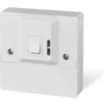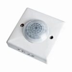
TIMEGUARD Motion Sensor PIR Light Switch – 2 Wire
General Information
These instructions should be read carefully in full prior to installation, and retained for further reference and maintenance.
Safety
- Before installation or maintenance, ensure the mains supply to the light switch is switched off and the circuit supply fuses are removed or the circuit breaker turned off.
- It is recommended that a qualified electrician is consulted or used for the installation of this light switch and install in accordance with the current IEE wiring and Building Regulations.
- Check that the total load on the circuit including when this light switch is fitted does not exceed the rating of the circuit cable, fuse or circuit breaker.
Technical Specifications
- Mains Supply: 230V AC 50 Hz
- Battery: 9V DC battery supplied (replaceable).
- 2 wire connection: No neutral required
- This light switch is of class II construction and must not be earthed
- Switch Type: Single or Two way
- Switch Rating: 2000W Incandescent/Halogen,
250W Fluorescent (Low-loss or Electronic Ballast),
250W CFL (Electronic Ballast),
400W LED Lighting (PF 0.9 or higher). - Minimum Depth of Wall Box: 25mm
- Operating Temperature: 0°C to +40°C
- Mounting Height: 1.1m for optimum detection range
- Detection Angle: 170°
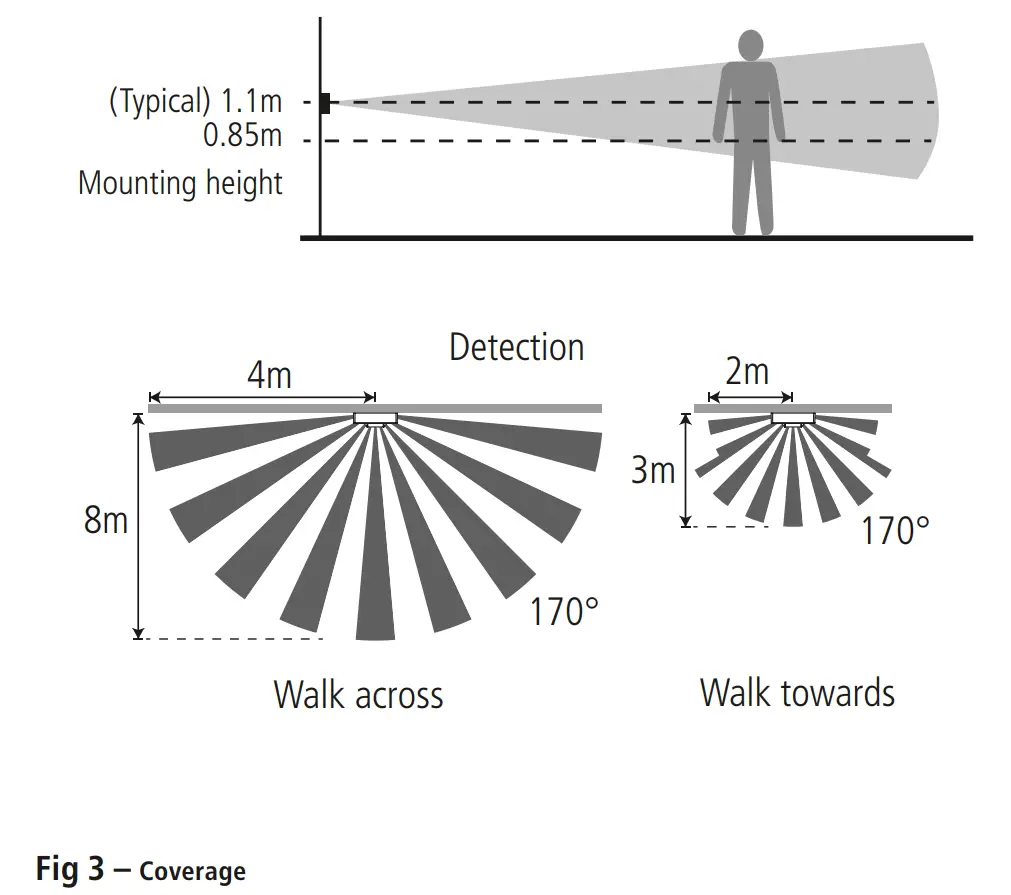
- Detection Range: 8m Front, 4m Sides
- Time ON Adjustment: 10 seconds (Min) to 15 minutes (Max)
- LUX Adjustment: 1 ~10lux (Moon symbol) to 1000lux (Sun symbol)
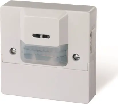
- Front Cover: Conceals Time/LUX adjustments and battery holder, with retaining screw
- Slide Switch: For Automatic and Manual ON/OFF selection
- DIP Switch: To enable or disable the Manual ON/OFF function.
- Motion Indication: Red LED turns ON for 1 second when motion detected
- Low Battery Indication: RED LED pulses 1 sec ON, 8 secs OFF
- CE Compliant
- Dimensions – H=86mm, W= 86mm, D=29.5mm

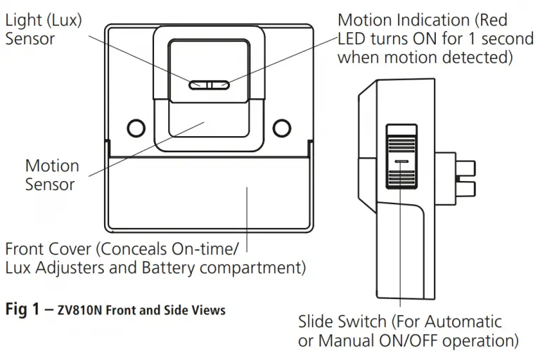
Selecting a Location
- For indoor use only i.e.: hallways, dining-room, basement, utility rooms and garages, etc. To replace existing one or two way light switches.
- Since the ZV810N is sensitive to temperature changes.
Avoid mounting directly above heat sources or exposed to direct sunlight. - Avoid mounting the motion sensor switch where it can come into contact with water or rain.
- For best results mount the sensor switch to detect objects moving across it.
Coverage
- The ZV810N can be mounted at heights between 0.85m to 1.5m.
The optimum height for detection is 1.1m, which we recommend to achieve the 8m range. Please note that that mounting it any higher will not give the same performance.
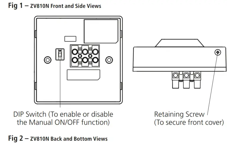
Installation
Note: The installation of this light switch should be protected by suitable circuit protection of up to 10A rating.
5.1 Ensure the mains supply is switched off and the circuit supply fused are removed or the circuit breaker is turned off, until you have completed the installation.
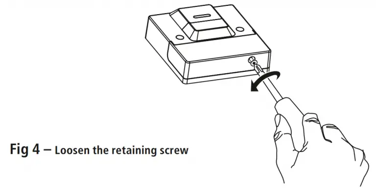
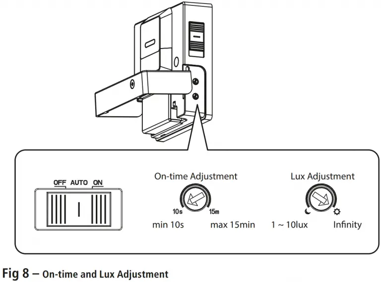
5.2 Loosen the retaining screw located on the bottom of the light switch, and open the hinged front cover that conceals the battery holder and On-time/Lux adjusters.
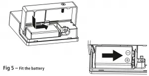
5.3 Fit the 9V battery (supplied) maintaining the correct polarity.
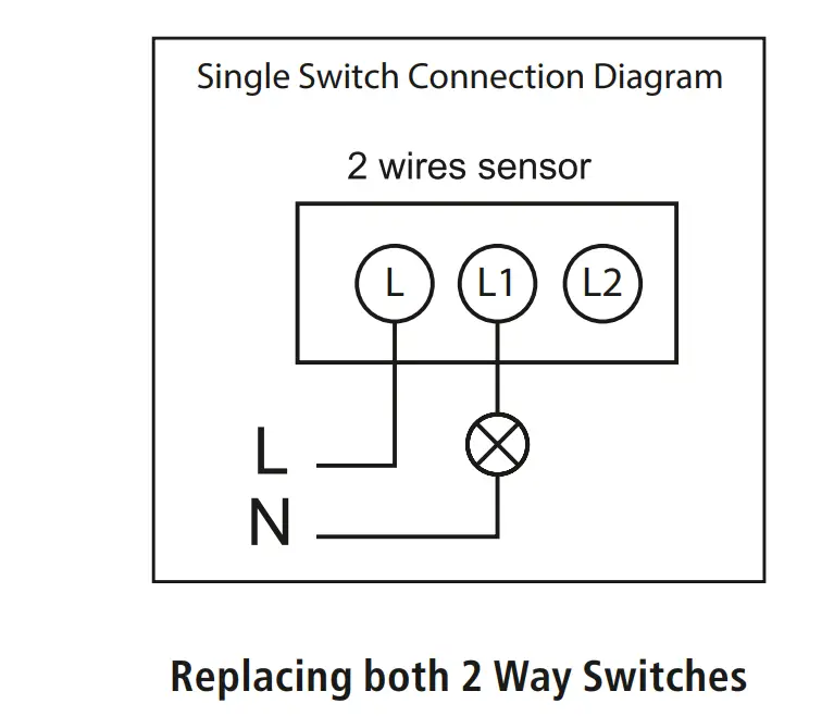
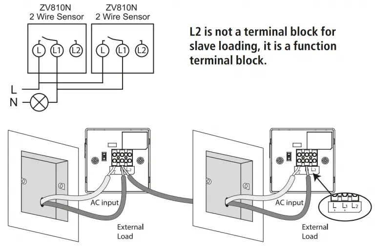
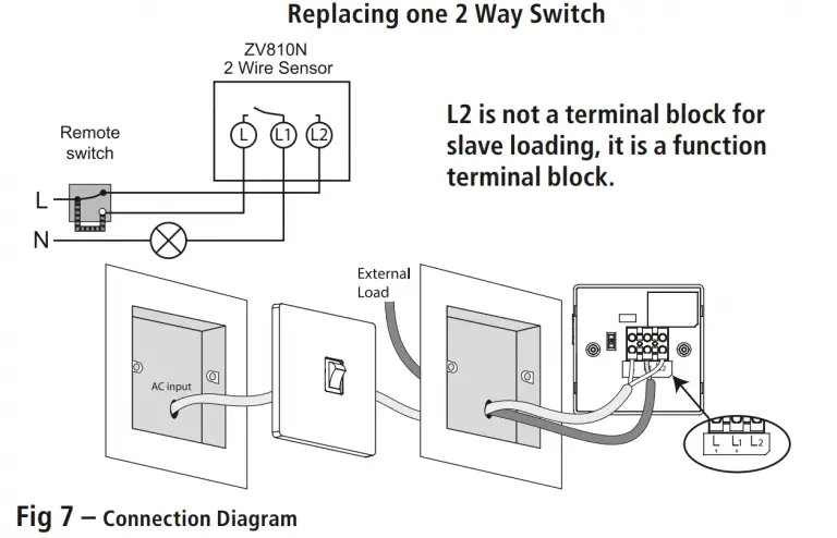
5.4 Remove the existing light switch, and transfer the wires to the ZV810N (See section 6.Connection Diagram).
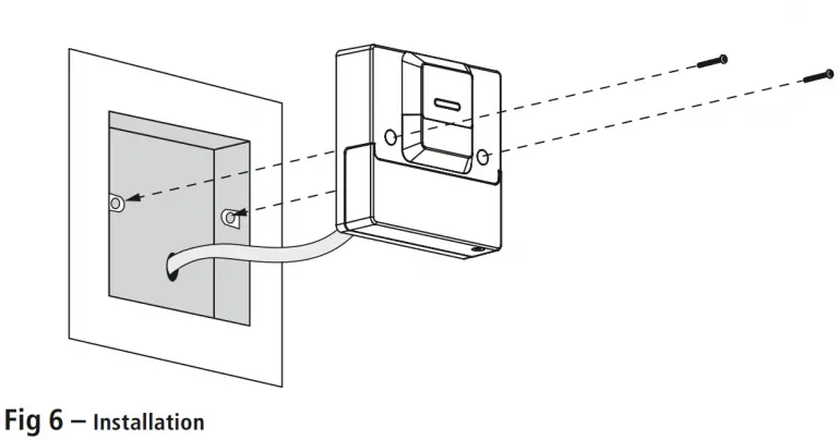
5.5 Secure the unit to the back box with the fixing screws provided, forming the cables during installation to avoid any entrapment and cable damage.
Connection Diagram
DIP Switch and Slide Switch
Note: The DIP Switch located on the back of the light switch can be used to enable or disable the Manual ON/OFF function, when using the Slide Switch. By default this will be set ON.
- If the DIP Switch is set to the ON (upwards) position, the Slide Switch can be used to turn your lights ON/OFF manually, or can be set to AUTO for motion control only.
- If the DIP Switch is set to the opposite (downwards) position, the Slide Switch will be disabled and your lights will turn ON using motion only.
Walk Test
Note: If the DIP Switch is set to the ON position, also make sure the Slide Switch is set to the AUTO (middle) position.
- Set the On-time adjuster fully anticlockwise to the min 10s position.
- Set the Lux adjuster fully clockwise to the SUN symbol.
- The light switch will now operate during the daytime as well as at night, illuminating your lights for approx. 10 seconds each time. This allows testing to be carried out to establish whether the sensor is covering the required area.
- Walk in front and around the sensor to establish the detection area. The sensor will detect motion within an 8m diameter (walking across), and within a 3m range (walking towards) with the sensor mounted at 1.1m.
- As you cross the detection ‘zone’ your lights will illuminate.
Now stand still until your lights extinguish (this should take approx. 10 seconds). - Start moving again after 2 seconds until your lights turn ON.
- Repeat the above, walking at various distances and angles from the light switch. This will help you confirm the detection pattern.
Setting up for Automatic Operation
- Turn the Lux Adjustment fully anti-clockwise to the Moon symbol.
- Turn the On-time Adjustment to the desired setting (10 seconds Minimum to 15 minutes Maximum).
- When the ambient light level reaches the level of darkness at which you wish the lamp to become operative once motion is detected (i.e. at dusk) SLOWLY rotate the control in an clockwise direction, whilst moving (e.g. your hand) in front of the sensor, until a point is reached where the lamp illuminates.
- Leave the Lux Adjustment set at this point.
- At this position, the unit should become operative at approximately the same level of darkness each evening each time motion is detected.
Adjustments
- If you find that your lights switch on when it is too dark, turn the Lux Adjustment clockwise towards the Sun symbol.
- If the light is in operation when it is too light, turn the Lux Adjustment towards the Moon symbol.
Low Battery Warning
- When the 9V battery is running low, the Motion Indication Red LED will pulse 1 second ON, 8 seconds OFF, as warning to change it (See section 5. Installation, step 5.2 & 5.3 for how to access the battery compartment).
Support
Note: If you have any concerns that the intended application of this product does not meet your requirements, please contact Timeguard directly prior to installation.
3 Year Guarantee
In the unlikely event of this product becoming faulty due to defective material or manufacture within 3 years of the date of purchase, please return it to your supplier in the first year with proof of purchase and it will be replaced free of charge. For the second and third years or any difficulty in the first year telephone the helpline on 020 8450 0515.
Note: A proof of purchase is required in all cases.
For all eligible replacements (where agreed by Timeguard) the customer is responsible for all shipping/postage charges outside of the UK.
All shipping costs are to be paid in advance before a replacement is sent out.
If you experience problems, do not immediately return the unit to the store.
Telephone the Timeguard Customer Helpline:
HELPLINE
020 8450 0515
or email [email protected]
Qualified Customer Support Coordinators will be online to assist in resolving your query.

