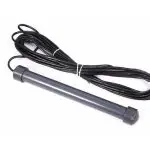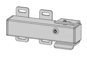
TOPENS ET24 Electric Lock User Manual
Important Note:
- The open & close delay time of the 2 actuatorsMUSTbesetto more than 4 seconds, if the electric lock isusedwithdual swing gate opener which is poweredbytheUPS01orDPS180-U AC-DC power supply. Otherwise, thegateopener will work improperly.
- Electric lock improves the safety for your gate, anditishighly recommended if you have animalsor liveinareasaffected by strong winds when the gate islongerthan1.2meters (4 feet).
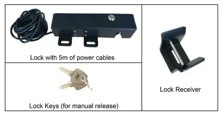
Electric Lock Part List
Important Information:
1
- Before you install the Electric Lock please be sure the gateis level ,moves freely, and does not bind or block against barriers. 2
- On the Pull-to-Open installation, for the Electric Locktoworkproperly, in order to ensure the lock engaging with the lockr eceiverf irmly, the limit switch B must be moved outward a littlebit morethanthe desired close position. 3. Due to the various mounting conditions, mounting hardwareisnotprovided. Read this manual carefully to determine the mountinghardware required for your condition.For dual gate, the lock must be installed on the Master Gate (gate 1) which is near the Control Box, and the lock receiver must be installed on the Slave Gate (gate 2).
- ( If the gate near the control box has been set up as slave gate, you can change the settings following “User’s Manual” → “Control Board Settings” – “Master/Slave Gate Set” )
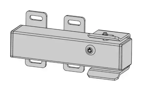
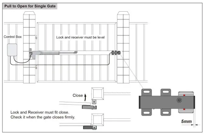
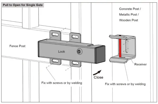
Installation for Single Gate
Step 1: Disengage the clutch of the opener with the Release Key. You can move the gate by hand, so the gate can swing freely during installation of the Electric Lock.
Step 2: With the gate in the closed position, determine the best location for the lock and receiver. The lock and receiver must be level and aligned with the opener. The lock and receiver should have a solid surface or tube fence to provide stability. Step 3: For Metallic Tube gate, if the thickness of the fence post is bigger than or equal to 3mm, you can thread on the fence post, and fasten the lock and receiver only using bolts (without nuts). Otherwise, drill holes through out the fence post, and fasten the lock and receiver with bolts, lock washers and nuts. Of course, you can weld them directly.
For Chain Link gate, you will need U-Bolts, saddles, lock washers and nuts for the lock and receiver.
Step 4: Recheck the lock’s position and alignment, make sure the electric
lock work correctly.
Step 5: Connect the lock’s power cables to the control board of TOPENS swing gate opener refers to the chapter “Wire Connection of the LOCK” . Note: Be sure that the clutch of the opener is engaged before you prepare to activate your opener (Use the Release Key).
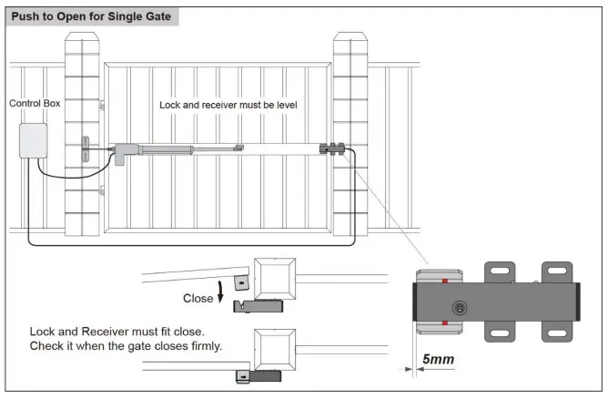
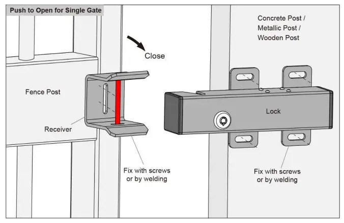
Installation for Dual Gate
Step 1: Disengage the clutches of the openers with the Release Key. You can move the gates by hand, so the gates can swing freely during installation of the Electric Lock.
Step 2: With the gates in the closed position, determine the best location for the lock and receiver. The lock and receiver must be level and aligned with the openers. The lock and receiver should have a solid surface or tube fence to provide stability.
Step 3: For Metallic Tube gates, if the thickness of the fence post is bigger than or equal to 3mm, you can thread on the fence post, and fasten the lock and receiver only using bolts (without nuts). Otherwise, drill holes through out the fence post, and fasten the lock and receiver with bolts, lock washers and nuts. Of course, you can weld them directly.
For Chain Link gates, you will need U-Bolts, saddles, lock washers and nuts for the lock and receiver.
Step 4: Recheck the lock’s position and alignment, make sure the electric lock work correctly.
Step 5: Connect the lock’s power cables to the control board of TOPENS swing gate opener refers to the chapter “Wire Connection of the LOCK”. Note: Be sure that the clutches of the openers are engaged before you prepare to activate your openers (Use the Release Key).
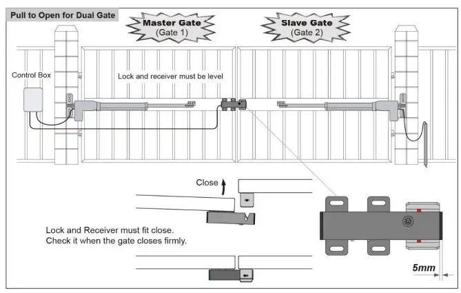
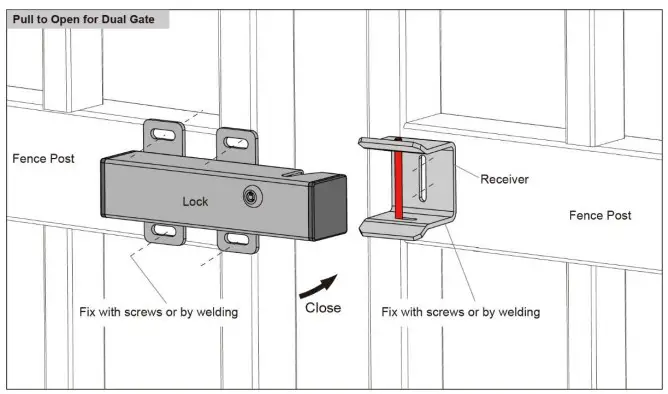
Wire Connection of the Lock
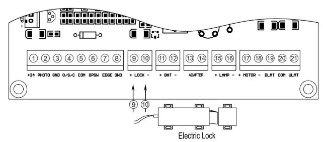
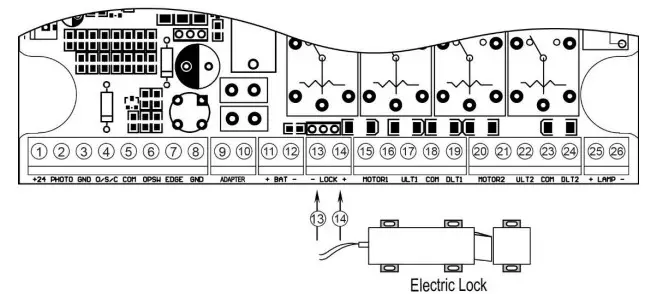
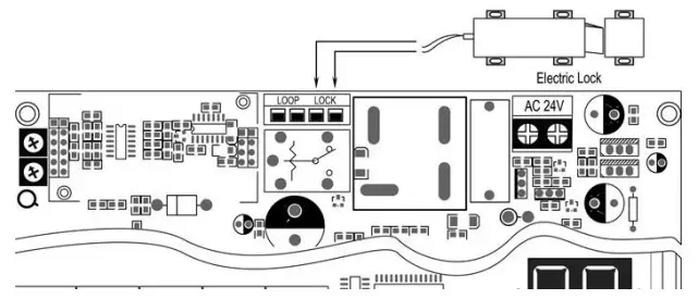
The electric lock can be wired to the “LOCK” terminal of the gate opener control board directly, no matter the polarity of the wires.
Wiring Diagram of the E-Lock to the A Series Single Swing Gate Opener
Wiring Diagram of the E-Lock to the AD&PW Series Dual Swing Gate Opener
Wiring Diagram of the E-Lock to the KD902, AT1202, MT8012, MT9012 Swing Gate Opener
NOTE: If the gate opener which you want to use the lock with is not listed in the above diagram, you can find the wiring diagram in the user manual of the gate opener, or contact us for technical support.
www.topens.com Any question, please do not hesitate to contact us:
E-mail: [email protected]
Kindly include your Product Model, Purchasing Date & Site, Order #, and your contact information. All your concerns will be replied within 24 hours.
Tel: +1 (888) 750 9899 (Toll Free USA & Canada)
